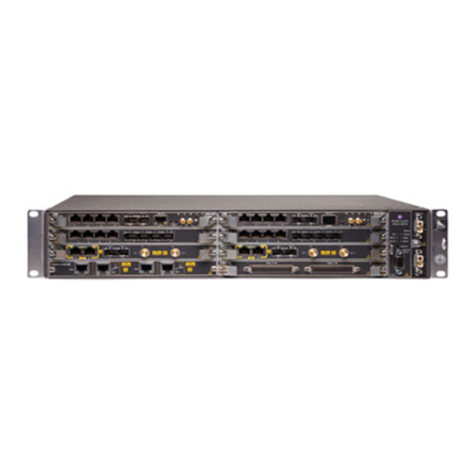
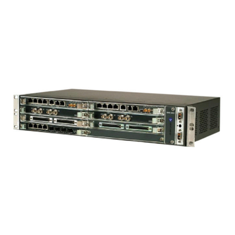
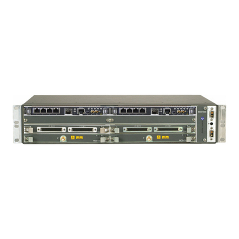
Alcatel-Lucent 9500 MPR User manual

Contact us for equipment purchase and repair services.
tempesttelecom.com | 800.879.4800

This CD (PN 3EM22841ABAA) contains the complete 9500 MPR Radio
Operation and Maintenance Manual. Refer to this CD for specific equipment
details not covered in the Users Manual.
9500 MPR Radio
Operation and Maintenance Manual

9500 MPR-A
Alcatel-Lucent Part Number 3EM22842AB
Issue 2, February, 2009
Microwave Packet Radio
Users Manual


NORTH AMERICA CUSTOMER SERVICE CENTER
24 HOURS PER DAY, 7 DAYS PER WEEK
PHONE the Call Center at
888-252-2832 (US and Canada)
or
613-784-6100 (International)
ALCATEL-LUCENT’S PRIMARY MISSION IS
SATISFYING OUR CUSTOMERS' QUALITY EXPECTATIONS.
The Call Center Agent (CSA)
Will help connect you with Technical Assistance (TAC)
Or assist you with a Repair and Return
• Phone-based technical support
• After-hour emergencies
• On-site
technical support
• E-mail
support [email protected]
•Software and hardware upgrades
TAC
• Module repair
Repair and Return
•Training http://www.alcatel-lucent.com>support
–Technical Training
Other Services Offered
•Field Services
–Installation and test
•Customized and Comprehensive Service Agreements
• Registration http://www.alcatel-lucent.com>MyAccess
– Once registered
–From “MyAlcatel” go to “Alcatel Support Documentation”
–
Register for access to documentation and e-mail update notifications
for Product Change Notices (PCN), product documentations, etc.
–Software and hardware upgrade documentation

Telephone Assistance, Normal Working Hours (CST 8am 5pm M-F)
TAC supports all Alcatel North America Microwave products. This includes routine questions and
emergency service.
Telephone Assistance, Emergency After-Hours
• Defined as loss of traffic, standby equipment, or network visibility on traffic-bearing systems.
• Available through our Customer Service Agents (CSA).
Contact Information Ask the Customer Service Agent (CSA) for a Microwave (MW) or a Network
Management Service engineer (NMS).
Please provide the following information to the Customer Service Agent (CSA):
• Last and first name
• Company name
• Telephone number
• City and state (street address if applicable) or site name and location
• Equipment type
• A brief description of the problem affecting their equipment
• Customer Priority: High, Medium, or Low.
• TL-9000 Severity as described below.
Creating A TAC Action Request (AR)
Critical
TL-9000 Severities Defined
Major
Minor Problems not classified as critical or major.
Problems severely affecting service, traffic, capacity, or network
management. They require immediate corrective action. (Ex.
Loss of network management capability, loss of traffic imminent
or existing).
Conditions seriously affecting system operation. They require
immediate attention. (Ex. processor outage, loss of standby
equipment, loss of remote access, or network managers).
TAC
Technical Assistance Center

TOC-1
Table of Contents
Page
1 General
1.1 Introduction ...............................................................................................................1-1
1.2 9500 MPR Overview ..................................................................................................1-1
1.3 9500 MPR Features List ...........................................................................................1-1
1.4 Typical System Configurations ................................................................................1-2
1.5 Physical, Electrical, and Environmental Characteristics .......................................1-3
1.5.1 Physical Characteristics ...........................................................................................1-3
1.5.2 Environmental Characteristics ................................................................................1-3
1.5.3 Basic Electrical Characteristics ...............................................................................1-4
1.5.4 Power Budget ............................................................................................................1-4
1.5.5 Fault and Configuration Management ....................................................................1-5
1.5.6 Antenna Interface .....................................................................................................1-5
1.5.7 Modem Profile – Split Mount - Static Modulation ..................................................1-6
1.5.8 Modem Profile – Split Mount - Adaptive Modulation .............................................1-7
1.6 MSS Shelf Configuration ..........................................................................................1-9
1.7 Parts List .................................................................................................................1-10
2 Operation
2.1 General ......................................................................................................................2-1
2.2 Turn-On .....................................................................................................................2-1
2.3 Craft Terminal (CT) Provisioning Function/Operation ..........................................2-1
2.4 Operating Procedures ...............................................................................................2-2
2.4.1 Rx Radio Protection Switching .................................................................................2-2
2.4.2 Tx (HSB) Radio Protection Switching ......................................................................2-4
2.4.3 Equipment Protection Switching .............................................................................2-5
2.5 Turn-Off Procedure ...................................................................................................2-6
2.6 Emergency Operation ...............................................................................................2-6
2.7 Module Controls, Indicators, and Connectors .........................................................2-6

TOC-2
Page
3 Interconnect
3.1 Section Introduction ................................................................................................. 3-1
3.2 Power Cable Connection ........................................................................................... 3-1
3.3 IF Connections .......................................................................................................... 3-3
3.3.1 MOD-300 to Type N Adapter Bracket Connections ................................................ 3-3
3.3.2 Type N Adapter Bracket to ODU Cable Connections ............................................. 3-3
3.4 DS1 Connections ....................................................................................................... 3-4
3.5 DS3 Connections ....................................................................................................... 3-9
3.5.1 Unprotected Configuration Cabling ........................................................................ 3-9
3.5.2 Protected Configuration Cabling ............................................................................. 3-9
3.6 Ethernet Cable Connections .................................................................................. 3-10
3.6.1 Automatic MDI/MDI-X Configuration ................................................................... 3-10
3.6.2 Crossover Cable Option .......................................................................................... 3-10
3.7 Network Management Systems (NMS) Connection ............................................. 3-13
3.8 Debug Port Connection ........................................................................................... 3-13
4 Initial Turnup
4.1 Section Introduction ................................................................................................. 4-1
4.2 Recommended Sequence .......................................................................................... 4-1
4.3 Security Management .............................................................................................. 4-1
4.4 Software .................................................................................................................... 4-2
4.4.1 Flash Card ................................................................................................................. 4-2
4.4.2 Software Load/License Key Upgrade ....................................................................... 4-3
4.5 Software Installation ................................................................................................ 4-3
4.5.1 Getting Started ......................................................................................................... 4-3
4.5.2 Download Overview .................................................................................................. 4-4
4.5.3 Java JRE Installation ............................................................................................... 4-7
4.5.4 Install WebEML (JUSM/CT) Software .................................................................. 4-10
4.5.5 Configure PC Network Card to Connect to NE ..................................................... 4-14
4.6 Start WebEML ........................................................................................................ 4-18
4.7 PROVISIONING Radio .......................................................................................... 4-20
4.7.1 Enable Plug-In Modules ......................................................................................... 4-21

TOC-3
Page
4.7.2 Provision Plug-In Modules ..................................................................................... 4-29
4.7.3 Protection Scheme Provisioning ............................................................................ 4-49
4.7.4 Provision Synchronization ..................................................................................... 4-63
4.7.5 Provision NE Time ..................................................................................................4-66
4.7.6 Cross Connections ...................................................................................................4-67
4.7.7 Provision System .................................................................................................... 4-78
4.7.8 Provision IP Static Routing .................................................................................... 4-79
4.7.9 Provision OSPF Static Routing .............................................................................. 4-80
4.7.10 Provision Local NE IP Address .............................................................................. 4-81
4.7.11 Re-configure PC Network Card ............................................................................. 4-82
5 Maintenance
5.1 Introduction .............................................................................................................. 5-1
5.2 Maintenance Philosophy .......................................................................................... 5-2
5.3 Personal Computer (PC)/Laptop .............................................................................. 5-2
5.4 Troubleshooting ........................................................................................................ 5-2
5.4.1 Before Going to Site Checklist .................................................................................5-2
5.4.2 Troubleshooting Basics .............................................................................................5-3
5.4.3 Troubleshooting Path Problems ............................................................................... 5-9
5.4.4 Troubleshooting Configuration Problems ............................................................. 5-11
5.4.5 Troubleshooting Ethernet Problems ...................................................................... 5-12
5.4.6 Troubleshooting TMN Problems ............................................................................ 5-13
5.5 Module Removal and REPLACEMENT Procedures ............................................ 5-15
5.5.1 CSM Removal and Replacement – In a CSM Protected Radio ............................ 5-17
5.5.2 CSM Flash Card Removal and Replacement ........................................................ 5-18
5.5.3 ODU Removal and Replacement ........................................................................... 5-18
5.6 CHANGING FREQUENCY ................................................................................... 5-20
5.7 Software Upgrade Procedures ............................................................................... 5-20
5.8 Upgrade From an UnProtected To A Protected Radio ......................................... 5-20
5.8.1 1+0 Static Modulation to 1+1 HSB in Static Modulation ..................................... 5-20
5.8.2 1+0 to 1+1 Frequency Diversity ............................................................................. 5-21
5.9 Downgrade from Protected to a UnProtected Radio ............................................. 5-22
TOC-4
Page
5.9.1 1+1 HSB in Static Modulation to 1+0 in Static Modulation ................................ 5-22
5.9.2 1+1 FD to 1+0 ......................................................................................................... 5-23
5.10 CLEANING ............................................................................................................. 5-25
6 User Guide
6.1 Introduction .............................................................................................................. 6-1
6.2 Local Craft Connection ............................................................................................. 6-1
6.2.1 Using the PC to Monitor and Control Local Radio ................................................. 6-1
6.2.2 Using the PC to Monitor and Control Remote Radio ............................................. 6-3
6.3 Configuration Menu ................................................................................................. 6-6
6.3.1 Cross-Connect Screen ............................................................................................... 6-6
6.3.2 Profiles Management Menu ..................................................................................... 6-9
6.4 Diagnosis Menu ...................................................................................................... 6-14
6.4.1 Remote Inventory ................................................................................................... 6-14
6.4.2 Abnormal Conditions .............................................................................................. 6-15
6.4.3 Summary Block Diagram View .............................................................................. 6-16
6.5 Supervision Menu ................................................................................................... 6-16
6.5.1 Supervision Dropdown Menu ................................................................................. 6-16
6.5.2 Access State Menu .................................................................................................. 6-17
6.5.3 SW License .............................................................................................................. 6-18

FM-i
SAFETY PRECAUTIONS
While the manufacturer has attempted to detail in this manual all areas of possible
danger to personnel in connection with the use of this equipment, personnel should
use caution when installing, checking out, operating, and servicing this equipment. As
with all electronic equipment, care should be taken to avoid electrical shock in all cir-
cuits where substantial currents or voltages may be present, either through design or
short circuit.
Definitions of Danger, Warnings, Cautions, and Notes used throughout this manual
are described below:
An operating procedure, practice, etc., which, if not correctly
followed could result in personal injury or loss of life.
An operating procedure, practice, etc., which, if not
strictly observed, could result in damage to or destruc-
tion of equipment.
An operating procedure, practice, etc., which, if not cor-
rectly followed, could result in an interruption of service.
An operating procedure, condition, etc., which is essential to highlight.
DANGER
Possibility of
Injury
to Personnel
WARNING
Possibility of
Damage
to Equipment
CAUTION
Possibility of
Service
Interruption
Note

FM-ii
9500-1166A
12/05/08

1
-
1
1
GENERAL
1.1 INTRODUCTION
The information in this Users Manual is a summary of the overall Operation and Mainte
-
nance Manual that is located on the attached CD. The summary information is provided to
support initial turnup, day-to-day operation, and maintenance of the 9500 MPR equipment.
1.2
9500 MPR OVERVIEW
Outdoor Radio Unit (ODU)
•
Optimal for urban links
•
Supports 6,
11,
15,
18 GHz
•
Integrated antenna mount
•
Coaxial connection to MSS
Microw
a
ve Service Switc
h (MSS)
•
Common shelf for nodal arc
hitecture
•
Consolidates RF spurs into one element
•
Both ODU and MPT
•
La
yer 2 aggregation
•
Ma
y be deployed standalone
1.3
9500 MPR FEATURES LIST
Refer to the following list of standard features
.
• DS1, DS3 and 10/100/1000 Ethernet interfaces
• CESoETH MEF8
• 300 Mbps full-duplex Ethernet transport capacity
• Flexible aggregate capacity sharing DS1/DS3 and Ethernet
• 10Gb Packet Based Node
• Microwave uplink (ODU V2)
• Ethernet uplink with VLAN
• Point-to-point VLAN
• IEEE 802.1p and Diffserv QoS
• Queue Management & Flow control ability
• DS1/DS3 Protection
9500-1141A
10/27/08
9500-1143
A
10/27/08

1
-
2
•
1+1 EPS on
All Cards
•
MXC ODU Support:
•
6,
11,
15,
18 GHz
•
Supported modulations:
•
32,
128,
256 QAM
•
Channel Spacing:
•
10,
30,
40,
50 MHz
•
Unprotected,
1+1 HSB & SD/FD Radio Protection
•
Node
,
up to 6 radio directions supported
•
SW License control
•
SNMP v2
•
TSM8000 Support
•
1340 INC Support
1.4
TYPICAL SYSTEM CONFIGURATIONS
The 9500 MPR is confi
gured as a split mount, with the MSS-8 shelf mounted indoors and
the ODU mounted on the tower. The MSS-8 shelf is connected to the ODU with coax cable.
The ODU can be direct-mounted to the antenna or mounted on the tower and connected to
the antenna with flex waveguide. The radio can function as follows:
• MSS-8 Stand Alone Shelf
•1+0 Terminal
• 1+0 Drop and Insert Repeater
• 1+1 Drop and Insert Repeater
• 1+0 4-Way Junction

1
-
3
1.5
PHYSICAL, ELECTRICAL, AND ENVIRONMENTAL CHARACTERISTICS
1.5.1 Physical Characteristics
Refer to
T
able 1-1for dimensions and weight for the MSS-8 shelf and ODU.
1.5.2
Environmental Characteristics
Refer to
T
able 1-2for temperature and humidity requirements for the MSS-8 shelf, and
ODU.
T
able 1-1 Physical Characteristics
Dimensions
(Width x Depth x Height)
MSS-8
444 x 250 x 88 mm (17.48 x 9.54 x 3.46 in.)
ODU
287 x 119 x 287 mm (11.299 x 4.68 x 11.29 in.)
W
eight
MSS-8 Fully Equipped
6 kg (13.2 lb.)
ODU
6 kg (13.2 lb.)
T
able 1-2 Environmental Characteristics
T
emperature
MSS-8
-5 to +55°C (+23 to +131°F)
ODU
-33 to +55°C (-17.4 to +131°F)
Humidity
MSS-8
0 to 95%, non-condensing
ODU
0 to 100%

1
-
4
1.5.3
Basic Electrical Characteristics
Refer to
T
able 1-3 for the basic electrical characteristics.
1.5.4
Power Budget
Refer to
T
able 1-4 for the power of the individual modules in the MSS-8 shelf, and ODU. To
determine the total power of the MSS-8 shelf, multiply the power of each individual mod-
ule by the number of that module installed in the shelf and add the resulting products. The
sum is the total power.
T
able 1-3 Basic Electrical Characteristics
Function
Characteristic
Power
-48 to +60 Vdc ± 20%
RF Frequency Band
5.8U, L6, U6, 11, 15, 18 GHz
Static Modulation
32, 138, 256 QAM
Adaptive Modulation
4, 16, 64 QAM
T
able 1-4 Power Budget
Component
Maximum Power
Consumption (W) Current (A)
CSM (Core) 16 0.33
MD300 (Radio) 23 0.48
P32E1DS1 (DS1) 16 0.33
P2E3DS3 (D3 16 0.33
FAN 8 0.17
ODU 30 0.63
Notes:
1. Power shown is for normal operation (not startup).
2. Current is based on a -48 Vdc battery input.

1-5
1.5.5 Fault and Configuration Management
Refer to Table 1-5for fault and configuration management options.
1.5.6 Antenna Interface
Refer to Table 1-6for helpful waveguide equipment information by frequency.
Table 1-5 Fault and Configuration Management
Function Characteristic
Protocol SNMP
Interface, Electrical Ethernet 10/100/1000Base-T
Interface, Physical RJ-45
Local/Remote configuration and Support Tool Craft Terminal
Routing protocols Supported Static and Dynamic Routing, OSPF
Network Management Alcatel-Lucent 1350 OMS and 5620 SAM
Table 1-6 Antenna Interface
Freq Band Radio
Flange
Waveguide
Mating
Flange
Waveguide
Type
Spring
Washers
Req’d.
Bolts
Req’d.
Bolt
Type
Thread
Spec
Hole
Depth
mm
Bolt Length
Required
6 GHz UDR70 PDR70 WR137 8 x M5 8 M5x0.8 6H 10 Flange thickness +
Hole depth - 2mm
7/8 GHz UDR84 PDR84 WR112 8 x M4 8 M4x0.7 6H 8 Flange thickness +
Hole depth - 2mm
10/11 GHz UDR100 PDR100 WR90 8 x M4 8 M4x0.7 6H 8 Flange thickness +
Hole depth - 2mm
13 GHz UBR120 PBR120 WR75 4 x M4 4 M4x0.7 6H 8 Flange thickness +
Hole depth - 2mm
15 GHz UBR140 PBR140 WR62 4 x M4 4 M4x0.7 6H 8 Flange thickness +
Hole depth - 2mm
18/23/26 GHz UBR220 PBR220 WR42 4 x M3 4 M3x0.5 6H 6 Flange thickness +
Hole depth - 2mm
28/32/38 GHz UBR320 PBR320 WR28 4 x M3 4 M3x0.5 6H 6 Flange thickness +
Hole depth - 2mm

1-6
1.5.7 Modem Profile – Split Mount - Static Modulation
Refer to Table 1-7 for useful transport signal details for a split mount radio provisioned for
static modulation (presetting mode).
Table 1-7 Modem Profile – Static Modulation
RF
Band
Channel
BW(MHz) Mod
Radio
Capacity
(Mbps)
Maximum
Equivalent
DS1
Capacity
Maximum
Equivalent
DS3
Capacity
Minimum
License
Required
Rx
Threshold
NS (dBM)
Rx
Threshold
HS (dBm)
Tx
PWR
(dBm)
System
Gain
NS
System
Gain
HS
5.8
GHz 10 128
QAM 52.640 31 1 80 -72.5 -71.0 24.5 97.0 95.5
L6
GHz
10
128
QAM 52.640 31 1 80 -72.5 -71.0 26.0 98.5 97.0
30
128
QAM 160.170 95 3 120 -68.0 -66.0 24.5 92.5 90.5
30
256
QAM 183.302 116 4 320 -64.0 -62.5 22.5 86.5 85.5
U6
GHz 10 128
QAM 52.640 31 1 80 -72.5 -71.0 24.5 97.0 95.5
11
GHz
10 128
QAM 52.640 31 1 80 -72.0 -70.5 20.0 92.0 90.5
30 32
QAM 114.22 67
2
120 -73.5 -72.0 21.5 95.0 93.5
30 128
QAM 160.170 95 3 160 -67.5 -65.5 20.0 87.5 85.5
30 256
QAM 183.302 116 4 320 -63.5 -62.0 18.0 81.5 80.0
40 32
QAM 152.293 90 3 160 -72.5 -71.0 18.0 90.5 89.0
40 128
QAM 213.935 126 4 320 -66.0 -64.5 18.0 84.0 82.5
15
GHz
10 32
QAM 37.323 22 22 NA 40 -77.5 -76.0 19.5 95.5
10 128
QAM 52.640 31 31 180 -71.0 -69.5 18.0 87.5
40 32
QAM 152.293 90 90 3160 -71.5 -70.0 19.5 89.5
40 128
QAM 213.935 126 126 4320 -65.0 -63.5 83.0 81.5
18
GHz
10 128
QAM 52.640 31 1 80 -70.5 -69.0 15.5 86.0 84.5
30 32
QAM 114.22 67 2 120 -72.0 -70.5 17.0 89.0 87.5
30 128
QAM 160.170 95 3 120 -66.0 -64.0 15.5 81.5 79.5
40 32
QAM 152.293 90 3 160 -71.0 -69.5 17.0 88.0 86.5
40 128
QAM 213.935 126 4 320 -64.5 -63.0 15.5 80.0 78.5
50 32
QAM 190.804 113 3 320 -70.0 -68.5 17.0 87.0 85.5
50 128
QAM 267.700 159 5 320 -63.5 -62.0 15.5 79.0 77.5

1-7
1.5.8 Modem Profile – Split Mount - Adaptive Modulation
Refer to Table 1-8for useful transport signal details for a split mount radio provisioned for
adaptive modulation.
Table 1-8 Modem Profile – Adaptive Modulation
RF
Band
Channel
BW(MHz) Mod
Radio
Capacity
(Mbps)
Maximum
Equivalent
DS1
Capacity
Maximum
Equivalent
DS3
Capacity
Minimum
License
Required
Rx
Threshold
NS (dBM)
Rx
Threshold
HS (dBm)
Tx
PWR
(dBm) *
System
Gain
NS
System
Gain
HS
L6
GHz
10
4
QAM 14.191 8 N/A 80 -88.0 -89.5 25.5 113.5 115.0
10
16
QAM 29.508 18 N/A 80 -82.0 -83.5 25.5 107.5 109.0
10
64
QAM 44.825 27 N/A 80 -76.0 -77.5 25.5 101.5 103.0
30
4
QAM 42.950 25 N/A 160 -83.5 -85.0 25.5 109.0 110.5
30
16
QAM 87.024 52 N/A 160 -77.5 -79.0 25.5 103.0 104.5
30
64
QAM 131.099 78 N/A 160 -71.5 -73.0 25.5 97.0 98.5
U6
GHz
10 4
QAM 14.191 8 N/A 80 -87.5 -89.0 25.5 113.0 114.5
10 16
QAM 29.508 18
N/A
80 -81.5 -83.0 25.5 107.0 108.5
10 64
QAM 44.825 27
N/A
80 -75.5 -77.0 25.5 101.0 102.5
30 4
QAM 42.950 25
N/A
160 -83.0 -84.5 25.5 108.5 110.0
30 16
QAM 87.024 52
N/A
160 -77.0 -78.5 25.5 102.5 104.4
30 64
QAM 131.099 78
N/A
160 -71.5 -73.0 25.5 97.0 98.5
11
GHz
10 4
QAM 14.191 8 N/A 80 -87.5 -89.0 21.0 108.5 110.0
10 16
QAM 29.508 18 N/A 80 -81.5 -83.0 21.0 102.5 104.0
10 64
QAM
44.825 27 N/A 80 -75.5 -77.0 21.0 96.5 98.0
30 4
QAM
42.950 25 N/A 160 -83.0 -84.5 21.0 104.0 105.5
30 16
QAM
87.024 52 N/A 160 -77.0 -78.5 21.0 98.0 99.5
30 64
QAM
131.099 78 N/A 160 -71.0 -72.5 21.0 92.0 93.5
15
GHz
10 4
QAM 14.191 8
N/A
80 -86.0 -87.5 19.0 105.0 106.5
10 16
QAM 29.508 18
N/A
80 -80.0 -81.5 19.0 99.0 100.5
10 64
QAM 44.825 27
N/A
80 -74.0 -75.5 19.0 93.0 94.5
30 4
QAM 42.950 25
N/A
160 -81.5 -83.0 19.0 100.5 102.0
30 16
QAM 87.024 52 N/A 160 -75.5 -77.0 19.0 94.5 96.0
30 64
QAM 131.099 78 N/A 160 -69.5 -71.0 19.0 88.5 90.0

1-8
* Based on 64 QAM
18
GHz
10 4
QAM
14.191 8 N/A 80 -86.0 -87.5 16.5 102.5 104.0
10 16
QAM
29.508 18 N/A 80 -80.0 -81.5 16.5 96.5 98.0
10 64
QAM
44.825 27 N/A 80 -74.0 -75.5 16.5 90.5 92.0
30 4
QAM
42.950 25 N/A 160 -81.5 -83.0 16.5 98.0 99.5
30 16
QAM
87.024 52 N/A 160 -75.5 -77.0 16.5 92.0 93.5
30 64
QAM
131.099 78 N/A 160 -69.5 -71.0 16.5 86.0 87.5
Table 1-8 Modem Profile – Adaptive Modulation (Cont.)
RF
Band
Channel
BW(MHz) Mod
Radio
Capacity
(Mbps)
Maximum
Equivalent
DS1
Capacity
Maximum
Equivalent
DS3
Capacity
Minimum
License
Required
Rx
Threshold
NS (dBM)
Rx
Threshold
HS (dBm)
Tx
PWR
(dBm) *
System
Gain
NS
System
Gain
HS
Other manuals for 9500 MPR
4
This manual suits for next models
1
Table of contents
Other Alcatel-Lucent Radio manuals

Alcatel-Lucent
Alcatel-Lucent 9500 MPR User manual

Alcatel-Lucent
Alcatel-Lucent MDR-8000 User manual

Alcatel-Lucent
Alcatel-Lucent 9768 User manual

Alcatel-Lucent
Alcatel-Lucent 9500 MPR-E User manual

Alcatel-Lucent
Alcatel-Lucent MDR-8000 User manual

Alcatel-Lucent
Alcatel-Lucent 9558HC User manual

Alcatel-Lucent
Alcatel-Lucent MDR-8000 User manual

Alcatel-Lucent
Alcatel-Lucent 9500 User manual

Alcatel-Lucent
Alcatel-Lucent 9500 MPR User manual

Alcatel-Lucent
Alcatel-Lucent MDR-8000 User manual