ALD-5404 Specification & Installation manual
4
Step Display Description Values
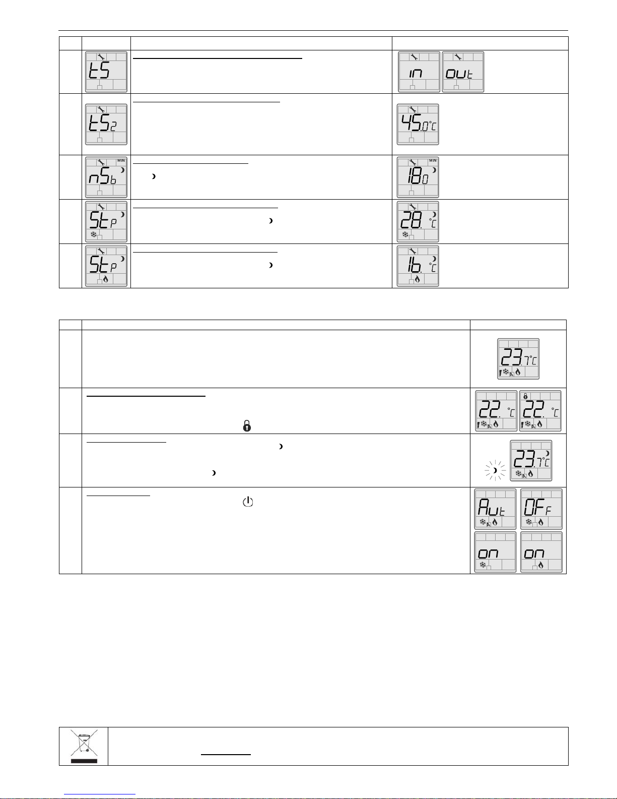
10A
Internal/external temperature sensor selection:
Display switches between “tS” and “in” or “out”.
Please select internal or external sensor.
Default value: Internal
temperature sensor
10B
External temperature sensor Calibration:
Display switches between “tS2” and the temperature read by the external
temperature sensor (if connected).
You can adjust the calibration of the external sensor by comparison with a
known thermometer.
Range: 0 to 50ºC [32 to 99.9ºF]
(max. offset ± 5ºC)
Increment: 0.1ºC [0.2ºF]
0.0ºC [32.0ºF], resistance will be
infinite.
50.0ºC [99.9ºF], résistance will be
short circuited.
11
Night set back derogation time :
Display switches between “nSb” and the derogation time in minute. MIN and
NSB symbol is also displayed.
Please select the desired derogation time, if no derogation time is desired
select “OFF”.
Range: OFF or 30 to 180min.
Increment: 15min.
Default value: 120 min.
12
Cooling Set point during Night set back:
Display switches between “Stp” and the value of the cooling set point
temperature during night set back. NSB and cooling symbols are also
displayed.
Please select the cooling set point temperature during night set back.
Range: 10 to 35ºC [50 to 95ºF]
Increment: 0.5ºC [1ºF]
Default value: 28ºC [83ºF]
13
Heating Set point during Night set back:
Display switches between “Stp” and the value of the heating set point
temperature during night set back. NSB and heating symbols are also
displayed.
Please select the heating set point temperature during night set back.
Range: 10 to 35ºC [50 to 95ºF]
Increment: 0.5ºC [1ºF]
Default value: 16ºC [61ºF]
Operation mode
Step Description Display
A
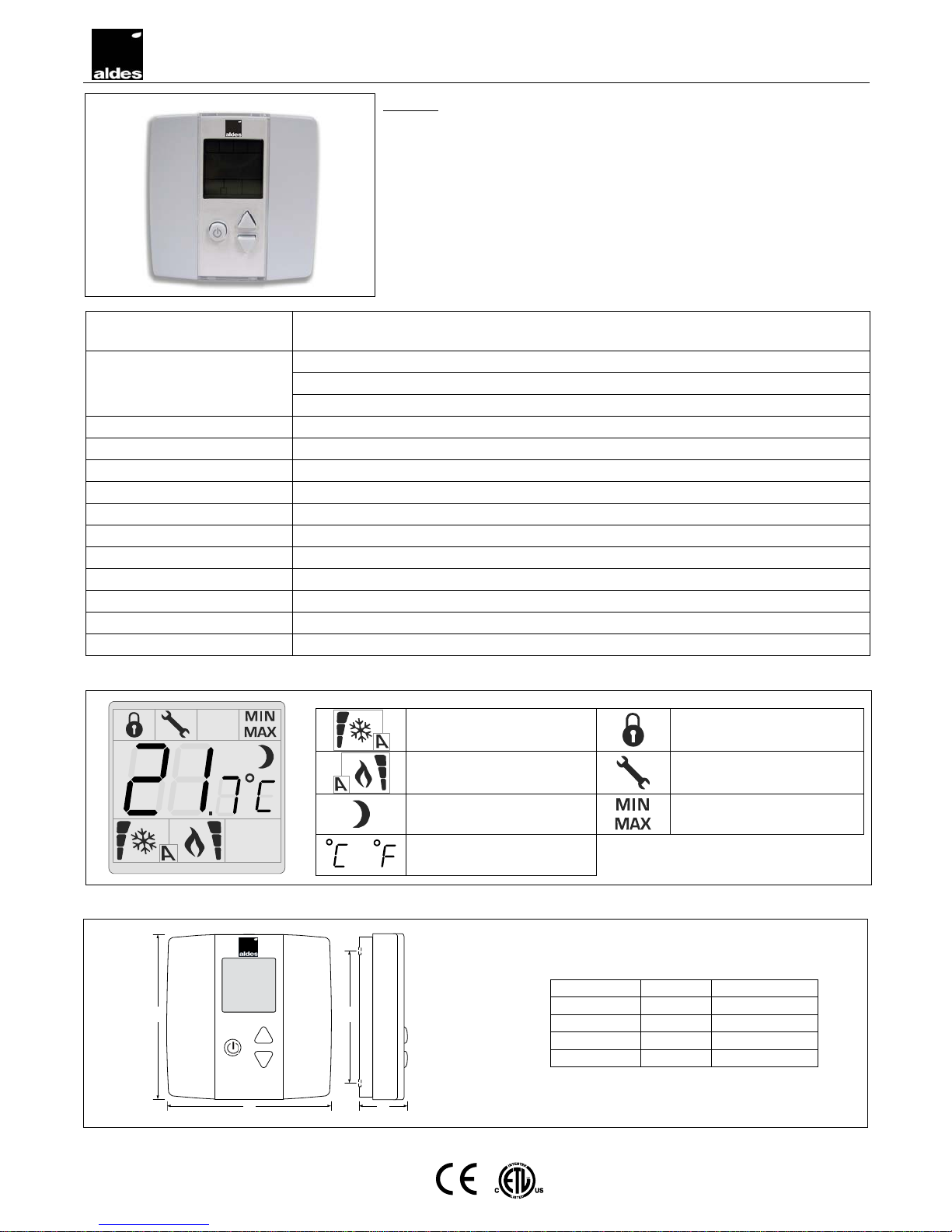
At powering up, thermostat will light display and activate all LCD segments during 2 seconds.
Illuminating the LCD.
To illuminate the LCD, you just have to push onto any of the 3 buttons. LCD will light for 8 seconds.
Temperature display
In operation mode, thermostat will automatically display temperature read.
To change the scale between ºC and ºF, press on both ∆and ∇for 3 seconds.
B
Set point display and adjustment
To display the set point, press two times onto any of the 3 buttons. Set point will be displayed during 5 seconds.
To adjust set point, press on ∆or ∇while the temperature set point is displayed.
Note: If set point adjustment has been locked, symbol will be displayed.
C
Night set back (NSB) :
When thermostat is in night set back mode, NSB symbol is displayed, so set point for cooling and/or heating
are increased as per the setting made in programming mode.
If not locked, night set back can be derogated for a predetermined period by pressing onto any of the 3 buttons.
During period of NSB derogation the symbol will flash. If NSB does not flash, the derogation period is finished
or the Night set back derogation has been locked in programming mode.
D
On/Off selection :
To set thermostat On/Off, press once onto the button. Control mode will be displayed during 5 seconds.
9Cooling only / OFF
9Heating only / OFF
9Automatic Cooling & Heating / Cooling only / Heating only / OFF
Note: These selections can vary according to the choice made on step #6.
Recycling at end of life
At end of life, please return the thermostat to your Aldes local distributor for recycling. If you need to find the nearest aldes authorized
distributor, please consult www.aldes.ae.