Alecto PRO-147 User manual

GEBRUIKSAANWIJZING
INSTRUCTION MANUAL
MODE D’EMPLOI
PRO-147

FUNCTIES
1 . Aan/uit schakelaar 12. Schuifregelaar mikrofoon 1
2. Lamp aansluiting 12V ~ 13. Schuifregelaars kanaal 1 t/m 4
3. Equalizer aanluit schakelaar 14. Mikrofoon 1 auto-mute schakelaar
4. Voorafluistering schakelaars 15. Keuze schakelaar cross-over fader
5. LED vu meter 16. Cross-over fader
6. 7-traps equalizer 17. Keuze schakelaar cross-over fader
7. Mikrofoon adapter 18. Schuifregelaar voorafluistering
8. Mikrofoon 2 ingangsbus 19. Schuifregelaar totaal volume
9. Mikrofoon 2 volume regelaar 20. Hoofdtelefoon uitgangsbus
10. Treble regelaar mikrofoon 1 21. Keuze schakelaars kanaal 1 t/m 4
11. Bass regelaar mikrofoon 1 22. Mono/stereo schakelaar
1
NL
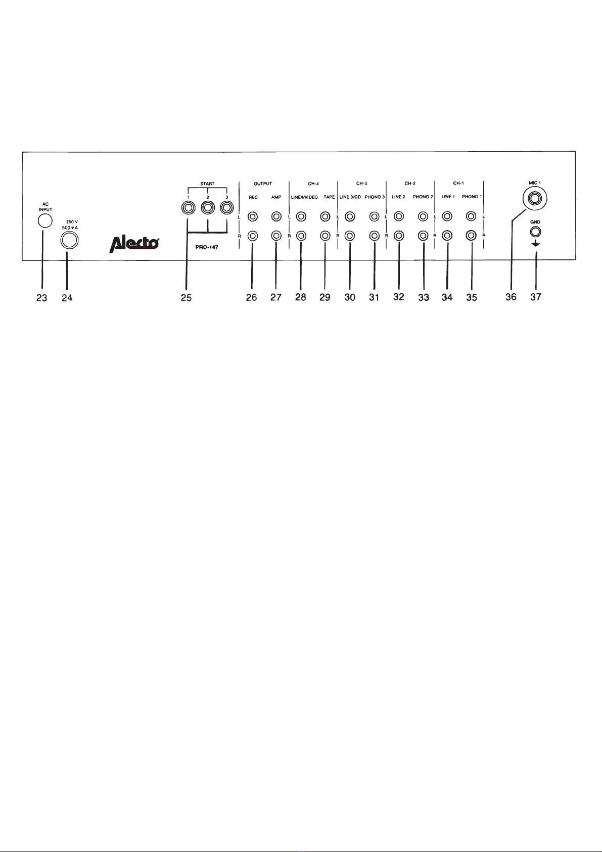
AANSLUITIINGEN
2
23. Aansluiting 220V snoer 31. Aansluiting phono 3
24. Zekeringhouder 32. Aansluiting line 2
25. Aansluitingen auto start 33. Aansluiting phono 2
26. Opname uitgang 34. Aansluiting line 1
27. Aansluiting naar versterker 35. Aansluiting phono 1
28. Aansluiting line 4/video 36. Mikrofoon 1 ingangsbus
29. Aansluiting tape 37. Aardeschroef t.b.v. draaitafels
30. Aansluiting line 3/cd
Uw semi-professionele 6-kanaals mengpaneel is ontworpen voor universele gebruiksdoeleinden in discotheek, huiskamer-
disco, voor mix-opnames etc. en is voorzien van een 7-traps equalizer, alsmede een totaalvolume-regelaar. De ruisarme
regelaars zorgen voor een betrouwbare mixing van de diverse aangesloten geluidsbronnen.
Tevens zijn kanaal 1,2 en 3 voorzien van de mogelijkheid om automatisch een draaitafel te starten (auto start).
Het volume van iedere ingang kan apart worden geregeld.
Als u zich, door bestudering van deze gebruiksaanwijzing, vertrouwd maakt met de vele mogelijkheden van dit
mengpaneel, zult u er voor lange tijd een optimaal plezier aan beleven.
GEBRUIKSAANWIJZING
ALGEMEEN

AANSLUITING
MIKROFOONS
PLATENSPELERS
AUTO START
LET OP: SCHAKELAARS ZIJN ALLEEN GESCHIKT VOOR LAAGSPANNING.
TAPE/TUNER/CD/VIDEO
Opmerking:
Allereerst dient de aan/uit schakelaar 1 in de uit-stand gezet te worden. Zet de volumeregeling van versterker en
mengpaneel op "0".
De ingang van de versterker (bijvoorbeeld aux) verbinden met de AMP uitgang (27) van het mengpaneel. Verdere
aansluitingen kunnen als volgt worden uitgevoerd:
lngangsbus 8 en ingangsbus 36 zijn voor aansluiting van een laagohmige mikrofoon. Het volume van de mikrofoon
aangesloten op 8 kan geregeld worden met draairegelaar 9. Het volume van de mikrofoon aangesloten op 36 kan
geregeld worden met schuifregelaar 12. Verder is deze aansluiting voorzien van een treble-(10) en een bass-regelaar
(11), en een auto mute schakelaar (14) welke in de stand "talk" het geluid van de overige geluidsbronnen enigszins
verzwakt.
Punt 7 is een mikrofoon-adaptor waar bijvoorbeeld een zwanenhals opgeschroefd kan worden.
Op de ingangen 31, 33 en 35 kunnen dr ie magneto-dynamische platenspelers aangesloten w orden (kanaalkeuze
schakelaars 21 op phono). Het bijbehorende volume wordt geregeld met de schuifregelaars van kanaal 1,2 en 3 (punt
13). Eventuele platenspelers met een keramisch element kunnen aangesloten worden op de line ingangen (Keuze
schakelaar 21 op line).
Kanaal 1, 2 en 3 zijn voorzien van een auto start funktie (punt 25). In de "0" stand van de schuifregelaars is het
(potentiaal vrij) kontakt open. Aansluiting is een 3,5 mm jackplug.
Aansluiting van deze vier muziekbronnen is mogelijk op de ingangen 28, 29, 30, 32, 34. Selektie van deze bronnen
geschiedt met de keuze schakelaars van kanaal 1 t/m 4 (punt 21). Volume nivo's worden geregeld met de
schuifregelaars van kanaal 1 t/m 4 (punt 13).
Voor het maken van tape opnames dient de line ingang van de tape rekorder verbonden te worden met de REC uitgang
(26) van de PRO-147.
De uitgeschakelde kanaal-ingangen worden door de PRO-147 kortgesloten. Dit heeft tot gevolg dat de hierop
aangesloten apparatuur niet meer funktioneer t.
3

HOOFDTELEFOON/MONITOR
EQUALIZER
FADER
MASTER
MONO/STEREO
VU METER
LICHT
Voor kontrole luisteren (voorafluistering) kan men een stereo-hoofdtelefoon aansluiten op uitgangsbus 20. Het
geluidsnivo kan men regelen met schuifregelaar 18. Met behulp van de voorafluistering schakelaars (4) bepaalt men
welk kanaal er afgeluisterd wordt (meerdere kanalen tegelijk mogelijk).
Met deze 7-traps toonregeling (6) is het mogelijk om voor alle kanalen de gewenste klankkleur in te stellen. Dit kan
onder verschillende omstandigheden tot opmer kelijke resultaten leiden. Met druktoets 3 is de equalizer in en uit te
schakelen; indien uitgeschakeld, wordt het orginele geluid ongewijzigd doorgelaten.
Deze schuifregelaar (16) maakt het overvloeien tussen twee kanalen mogelijk. Door instelling van de "assign"
draairegelaars (15 en 17) wordt bepaald tussen welke twee kanalen het overvloeien plaats vindt. Indien men
bijvoorbeeld wil overvloeien, van kanaal 1 naar kanaal 2, wordt "assign" regelaar 15 op 1 gezet en "assign" regelaar
17 op 2. Als deze funktie niet gebruikt wordt dienen beide regelaars op "off" te staan.
Met deze schuifregelaar (19) wordt het volume-nivo van alle kanalen tegelijk geregeld.
Keuze schakelaar (22) voor mono of stereo uitgangssignaal.
Het uitgangssignaal wordt gekontroleerd door middel van de twee LED vu meters (5). Deze dienen niet overmatig in
het rode gedeelte te komen.
BNC aansluiting 12V AC. t.b.v. lampje. LET OP: maximale stroom afname 100 mA (1,2 Watt). Overschrijding van
deze waarde leidt tot een gebrekkig funktioneren van de PRO-147 en het uiteindelijk defekt raken van de voedings
trafo.
4

ONDERHOUD
SPECIFIKATIES
GEVOELIGHEID:
IMPEPANTIE:
EQUALIZER:
LICHT
UITGANGSSPANNING
VERVORMING
FREQUENTIE BEREIK
SIGNAAL/RUISVERHOUDING
HOOFDTELEFOON
VOEDING
AFMETINGEN
Plaats de PRO-147 op een vlak/stabiel opper vlak en zorg ervoor dat er geen loshangende kabels in de weg zitten.
Loshangende bekabeling en plaatsing op een onstabiel opper vlak verhogen het risico van ongelukken en
beschadigingen. Indien gewenst kan de PRO-147 ook ingebouwd worden.
Voor het reinigen van het kabinet uitsluitend een vochtige doek gebruiken. Vloeibare (chemische)
reinigingsmiddelen zullen het apparaat onherroepelijk beschadigen.
Probeer in geval van een storing de PRO-147 niet zelf te repareren. Reparaties dienen uitsluitend door bevoegd,
gekwalificeerd personeel uitgevoerd te worden. Reparaties uitgevoerd door derden leiden tot het vervallen van de
garantie.
PHONO 1, 2, 3 .............................................................................3mV
MIC 1, 2.......................................................................................1 mV
LINE 1, 2, 3, 4.........................................................................150 mV
PHONO 1, 2, 3.......................................................................47 K ohm
MIC 1, 2 ................................................................................600 ohm
LINE 1, 2, 3, 4 .......................................................................47 K ohm
FREQUENTIES ................................................60 Hz, 150 Hz, 400 Hz,
1 KHz, 2.4 KHz, 6 KHz,
15 KHz ± 12 dB
.....................................................................................................12V/A C 100 mA MAX
........................................................................................................1.2V
..............................................................................................................< 0.1%
.............................................................................20 Hz - 20KHz ± 3 dB
........................................................................................> 58 dB
............................................................................................2V. MAX/8 ohm
..............................................................................................................220V150 Hz
.....................................................................................480mm, 240mm (front)
100mm (hoogte zonder
handgrepen)
5
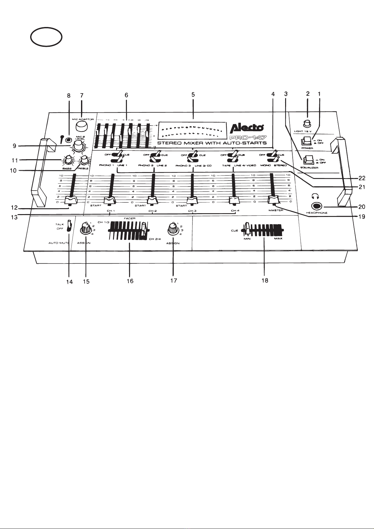
FUNCTIONALITY
1. On/off switch 12.Volume slide microphone 1
2. Light connection 12V 13. Volume slides channel 1-4
3. Equalizer on/off switch 14. Microphone 1 auto mute switch
4. Monitor switches 15. Selector cross-over fader
5. LED vu meter 16. Cross-over fader
6. Equalizer controls 17. Selector cross-over fader
7. Microphone adaptor 18. Monitoring volume slide
8. Microphone 2 input 19. Master volume slide
9. Microphone 2 volume control 20. Headphone output
10. Treble control 21. Input selectors channel 1-4
11. Bass control 22. Mono/stereo switch
6
GB

CONNECTIONS
7
23. AC cable 31. Inputs phono 3
24. Fuse holder 32. lnputs line 2
25. "START" switch connect jacks 33. Inputs phono 2
26. Recording output 34. Inputs line 1
27. Amplifier output 35. Inputs phono 2
28. Inputs line 4/video 36. Inputs microphone 1
29. Inputs tape 37. Earth screw
30. Inputs line 3/cd
- The soundmixer PRO-147 has been designed for various professional applications in discotheque,
room-disco, mix-recordings etc.
- The mixer does have a lot of features like a 7-channel equalizer, monitoring, auto-start on
3 channels, tonecontrol on mix-channel, fader-control etc.
- Please acquaint yourself with the possibilities of this mixer by studying this manual carefully.
INSTRUCTION MANUAL
MAIN FEATURES

CONNECTION INSTRUCTIONS
MICROPHONES
PHONOS
AUTO START
TAPE/TUNER/CD/VIDEO
Make sure that the "POWER" switch of the mixer is in "OFF" position. - Plug shielded audio cables from mixer output
(27) to your amplifier input. - Turn the amplifier volume control to its lowest position. - Turn the mixer volume control
to "0" position.
Two low impedance microphones may be used with this mixer.
Microphone 1: the volume level of microphone 1 is adjusted by slide control 12. Treble and Bass are adjusted by
rotary controllers 10 and 11. When switch 14 is in "talk" position, the master output level will reduce automatically
without affecting the volume level of mic. 1 (auto mute).
Microphone 2: the volume level of microphone 2 is adjusted by rotary controller 9.
Three magneto-dynamic record-players can be connected to inputs 31, 33 and 35 (switches 21 in phono position).
Volume level is controlled by slides 13. Ceramic record-players can be connected to the line inputs (switch 21 in line
position).
Channels 1, 2, and 3 are connected with three switches who are controlled by slides ch.1/2/3. When setting the slide
level controller to "0" position, the switch is "open" (OFF) and if set to over "l" position the switch will be "short" (ON).
Connectors: 3.5 mm jack. CAUTION: SWITCHES ONLY TO BE USED WITH LOW VOLTAGE.
These audio sources must be connected to inputs 28, 29, 30, 32, 34 (switches 21 in matching position). Volume
levels are controlled by slides 13. When required the recording input jacks of a tape recorder can be connected to
the mixers recording output jacks (26).
Note: Switched-off inputs will be automatically shor t-circuited (this means that an audio source wil not function when
connected).
8

MONITORING
EQUALIZER
FADER
MASTER
MONO/STEREO
VU METER
LIGHT
The headphone jack (20) is used to monitor (6.3 mm jack). Use an eight ohms stereo headphone. With the cue
switches (4) it is possible to choose any channel (monitoring two or more channels simultaneously possible). Volume
level is adjustable by slide control 18.
This mixer features a 7 channel equalizer (6), which may be used to adjust the tone of the mixed output signal. lf the
equalizer is not needed, depress switch 3 to make a flat output signal.
Control slide (16) to fade from one channel to another. Channel selection is made with rotar y selectors 15 and 17.
For instance; when fading from channel 1 to channel 2, set switch 15 in position "l and switch 17 in position "2".
When this function is not needed, set both rotar y switches in position "Off".
Control slide (19) to adjust the volume of the overall mix.
Selector (22) for mono or stereo output signal.
LED vu meter (5). Displays the output level of the complete mix.
BNC connector 12V AC. for lamp holder.
CAUTION: maximum current 100 mA (1,2 Watt).
Exceeding the maximum currect will result in malfunctioning of the mixer, which also may cause a defective power
transformer.
9

MAINTENANCE
SPECIFICATIONS
INPUT SENSITIVITY
IMPEDANCE:
EQUALIZER:
CENTER FREQUENCY
LIGHT
OUTPUT LEVEL
HARMONIC DISTORTION
FREQUENCY RESPONSE
S/N RATIO
PHONES OUTPUT
POWER SOURCE
DIMENSION
Use the PRO-147 on a stable surface. An unstable mounting surface could cause the device to fall.
Use a damp cloth for cleaning. Do not use liquid or aerosol cleaners.
Do not attempt to service the PRO-147 yourself. Any unauthorized servicing may damage the PRO-147 and will void
the warranty.
PHONO 1, 2, 3 .................................................................................3 mV
MIC 1,2 ...........................................................................................1 mV
LINE 1, 2, 3, 4 ..............................................................................150mV
PHONO 1, 2, 3 ...........................................................................47 Kohm
MIC 1, 2 .....................................................................................600 ohm
LINE 1, 2, 3, 4............................................................................47 K ohm
................................................................................60 Hz, 150 Hz, 400 Hz,
1 KHz, 2.4 KHz, 6 KHz,
15 KHz ± 12, dB
........................................................................................................12V/A C 100 mA MAX
....................................................................................................................1.2V
................................................................................................< 0.1 %
...............................................................................20 Hz - 20 KHz ± dB
........................................................................................................................> 58 dB
.................................................................................................2V. MAX/8 ohm
...................................................................................................... 220V150 Hz
............................................................................................480mm, 240mm (front)
100mm (height without
handles)
10

FONCTIONS
1. Bouton de mise en route
2. Connexion pour une lampe de 12V
3. Commutateur ON/OFF du correcteur de fréquences
4. Commutateurs pré-écouter
5. LED vu mètre
6. Correcteur de fréquences en 7 paliers
7. Adapteur microphone
8. Conduit d'entrée microphone 2
9. Régulateur du volume microphone 2
10. Réglage des aiguës
11. Réglage pour les tons bas
12. Commutateur coulissant microphone 1
13. Commutateurs coulissants canal 1/4
14. Commutateur assourdisseur automatique microphone 1
15. Commutateur sélecteur cross-over fader
16. Commutateur à parler sur un fond musical
17. Commutateur sélecteur cross-over fader
18. Commutateurs coulissant pré-écouter
19. Commutateur coulissant volume total
20. Conduit de sortie casque d'écoute
21. Commutateur sélecteur canals 1/4
22. Commutateur mono/stéréo
F

RACCORDEMENTS
COMMENTAIRES GENERAUX
Votre table de mixage à 6 canals est projeter pour une utilisation universelle pour le disco chez vous, les
discothèques, des enregistrements, etc. La PRO-147 est équipée d'un correcteur de fréquences en 7 paliers
et d'un régulateur pour Ie volume total. Grâce au commutateurs anti-bruit vous obtiendrez une mixage de
différentes sources de bruit, parfaite. En outre, les canals 1, 2. et trois permettent un démarrage automatique
de la table rotative (cfr. 25).
Le volume de chaque canal peut être réglé séparément.
Etudier le mode d'emploi pour obtenir un plaisir optimal de cette table de mixage.
23. Raccordement fil de 220V
24. Garde fusible
25. Raccordements auto start
26. Sortie enregistrement
27. Raccordement à l'amplificateur
28. Raccordement ligne 4/vidéo
29. Raccordement enregistreur
31. Raccordement phono 3
32. Raccordement ligne 2
33. Raccordement phono 2
34. Raccordement ligne 1
35. Raccordement phono 1
36. Boîte d'entrée microphone 1
37. Vis GND pour tournes-disques

RACCORDEMENT
MICROPHONES
TOURNE-DISQUES :
AUTO START
ENREGISTREUR/TUNER/CD/VIDEO :
CASQUE D'ECOUTE :
Placer commutateur 1 en position OFF (non-active). Régler Ie volume de L amplifateur et de la table de mixage sur
« 0 ». Raccorder l 'entrée de l'amplificateur (p.e. aux.) à la sortie AMP (27) du
Mélangeur. Les autres connexions pourraient être exécutées comme suite.
Les conduits d'entrées 8 et 36 sont pourvus pour le raccordement d'un microphone en ohm bas. Le volume du
microphone, branché sur l'entrée 8. sera réglé avec l'Interrupteur rotatif 9. Le volume du microphone, branché sur
36, sera réglé avec le commutateur coulissant 12. En plus, le raccordement microphones est équipé avec
-un réglage des aiguës (10)
-un régulateur pour les tons bas (11)
-un commutateur auto mute (14) lequel represse les sons d'autres sources sonores en position "TALK" (parlez).
Trois tournes-disques magnétodynamique seront raccordés sur les entrées 31 33 et 35 (commutateur 21 en phono
. Le volume correspondant sera réglé á l'aaide du commutateurs coullisant de canal 1, 2 et 3 (point 13). Les
tournes-disques avec un élément céramique, seront raccordés sur les entrées LIGNE (commutateur 21 en ligne).
Canals 1, 2 et 3 sont pourvus d'une fonction 'auto start' (cfr. 25). Le contact est ouvert quand les régulateurs
coulissant sont en position "0". Le raccordement est une cheville de 3,5 mm.
Raccordement de cettes sources sonore est possible aux entrées 28, 29, 30, 32 et 34. La sélection de cettes
sources se passe avec les commutateurs sélecteur du canal 1/4 (cfr, 21). Le volume est réglé avec les
commutateurs coulissant du canal 1 jusgu'à 4 (cfr 13). Raccorder léntrée 'ligne'de votre magnétophone 1à la sortie
REC (23) du PRO-147 afin d'avoir la possibilité de registrer les sons sur une cassette.
Remarque : Les entrées des canals non-active seront mis en court-circuit par le
PRO-147. Ca aura pour conséquence que tous les appareils, y-connecté, ne fonctionnent plus.
Raccorder un casque d'écoute conduit de sortie no : 20 si vous désirez contròler les sons enregistrés. Régler le
niveau du volume avec le commutateur coulissant 18. A l'aide du commutateur pré-écouter (4) vous déterminez le
canal á écouter (il est possible d'écouter aux plusieurs canals en même temps).
ATTENTION : LES COMMUTATEURS SONT SEULEMENT PROPRE A BASSE TENSION.

CORRECTEUR DE FREQUENCES
FADER :
MASTER
MONO/STEREO
VU METRE
LAMPE :
NETTOYAGE
Cette contrôle tonalité (cfr. 6) vous donne lapossibilité de régler le timbre de chaque canal . Ceci peut produire des
résultats remarquable. Le son original sera Inchangé si le correcteur de fréquences est hors service.
Par ajuster les commutateurs 15 et 17 ("assign" = indiquer) vous Installez les deux canals à fondre. SIi par exemple.
vous voudriez fondre du canal 1 à canal 2, mettez régulateur 15 à 1 et régulateur 17 à 2. Si vous ne désirez pas
utiliser cette fonction, les deux commutateurs se trouvent en position "OFF".
Le niveau du volume de chaque canal sera réglé en même temps (cfr. Commutateur 19)
Commutateur sélecteur (22) pour un signal de sortie en mono ou en stéréo.
Le signal de sortie sera controlé par deux LED vu mètres (5).
Raccordement CA 12V.
Placer le PRO-147 sur une surface stable. Bien veiller à ce que les câbles ne puissent pas être piétinés. Le câblage
pendu augmente le risque de dégâts. La PRO-147 peut être incorporé si désirer.
Debrancher l 'appareil avant de le nettoyer. Nes pas utiliser d'aérosols ou de liquides nettoyants. Utiliser un chiffon
doux. En cas d'une perturbation n'essayez jamals de réparer la PRO-147 vous-même. L'appareil ne peut être réparé
que par des personnes qualifiés. Réparations fait par des tiers auraient l'annulation de la garantie pour conséquence.
Attention : Dimunition de courant maximale : 100 mA (1.2 Watt)
Dépassage de cette valeur causera un fonctionement défectueux de la PR0-14
ENTRETIEN

DONNEES TECHNIQUES
SENSIBILITÉ
IMPÉDANCE:
CORRECTEUR:
FREQUENCES
LAMPE
TENSION DE SORTIE
DISTORSION
GAMME DE FRÉQUENCE
RAPPORT SIGNAL/BRUIT
CASQUE D’ÉCOUTEONES
ALIMENTATION
DIMENSIONS
PHONO 1, 2, 3 .................................................................................3 mV
MIC 1,2 ...........................................................................................1 mV
LIGNE 1, 2, 3, 4 ...........................................................................150mV
PHONO 1, 2, 3 ...........................................................................47 Kohm
MIC 1, 2 .....................................................................................600 ohm
LIGNE 1, 2, 3, 4..........................................................................47 K ohm
............................................................................................ 60 Hz, 150 Hz, 400 Hz,
1 KHz, 2.4 KHz, 6 KHz,
15 KHz ± 12, dB
........................................................................................................12V/A C 100 mA MAX
..............................................................................................................1.2V
.....................................................................................................................< 0.1 %
................................................................................20 Hz - 20 KHz ± dB
...................................................................................................> 58 dB
.......................................................................................2V. MAX/8 ohm
.......................................................................................................... 220V150 Hz
............................................................................................480mm, 240mm (front)
100mm (height without
handles)
Table of contents
Languages:
Other Alecto Music Mixer manuals


Popular Music Mixer manuals by other brands

Professional Sound Corporation
Professional Sound Corporation DV Promix 3 quick start guide

Philips
Philips SOPHO SuperVisor 25 Engineer's manual

Z Microsystems
Z Microsystems COMMAND CONSOLE 14 user manual

Behringer
Behringer EUROPOWER PMP2000 user manual

Tascam
Tascam TEAC PROFESSIONAL M-164 owner's manual

Midas
Midas Pro 6 DL351 Operator's manual


