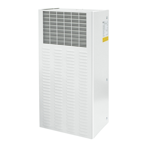
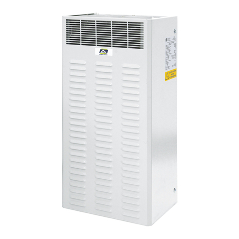
Alfa Electric AVE145 User manual

Designation: AIR CONDITIONER FOR ELECTRICAL ENCLOSURE Page 1/23
UMA-CDZ-AVE145-01
USER’S MANUAL (PART 2)
AIR CONDITIONER FOR ELECTRICAL ENCLOSURE
OUTDOOR APPLICATION
AVE145
Division of:
ALFAPLASTIC s.a.s.
Via Della Valle, 39 – 20841 Carate Brianza (MB) Italy
Tel. +39 (0362) 903.539 Fax. +39 (0362) 975.133
Mail: info@alfaelectric.com
www.alfaelectric.com
Document: UMA-CDZ-AVE145-01 Date Name
Description
Original user’s manual for air conditioner AVE145 series
Language: English
ISSUE 07/01/2019 Ascheri M.
REV. 01 04/08/2021 Ascheri M.
REV. 02
REV. 03

Designation: AIR CONDITIONER FOR ELECTRICAL ENCLOSURE Page 2/23
UMA-CDZ-AVE145-01

Designation: AIR CONDITIONER FOR ELECTRICAL ENCLOSURE Page 3/23
UMA-CDZ-AVE145-01
TABLE OF CONTENTS
1 - TECHNICAL DATA ................................................................................................................... 4
2 - INSTALLATION ....................................................................................................................... 5
2.1 PRODUCT HANDLING .................................................................................................... 5
2.2 GENERAL CHECKS BEFORE INSTALLATION ..................................................................... 5
2.3 FITTING ........................................................................................................................ 6
3 - ELECTRICAL CONNECTION ...................................................................................................... 8
3.1 WIRING DIAGRAM ........................................................................................................ 9
3.1.1 AVE145.000 ........................................................................................................... 9
3.1.2 AVE145.010 ......................................................................................................... 10
3.1.3 AVE145.020 ......................................................................................................... 11
3.1.4 AVE145.001 ......................................................................................................... 12
3.1.5 AVE145.011 ......................................................................................................... 13
3.1.6 AVE145.021 ......................................................................................................... 14
4 - STARTING AND ADJUSTMENT .............................................................................................. 15
4.1 DIGITAL THERMOSTAT ................................................................................................ 15
4.2 MECHANICAL THERMOSTAT ....................................................................................... 18
5 – SPARE PARTS LIST ............................................................................................................... 19
5.1- SPARE PARTS FOR AVE145.000, AVE145.010, AVE145.020 .............................................. 19
5.2- SPARE PARTS FOR AVE145.001, AVE145.011, AVE145.021 .............................................. 19
6 - ACCESSORIES ....................................................................................................................... 20
6.1 FLOW DIVERTER ......................................................................................................... 20
6.1.1 Flow diverter installation ..................................................................................... 20
WARRANTY .............................................................................................................................. 21
UE DECLARATION OF CONFORMITY .......................................................................................... 22

Designation: AIR CONDITIONER FOR ELECTRICAL ENCLOSURE Page 4/23
UMA-CDZ-AVE145-01
1
-
TECHNICAL
DATA
CONTROL TYPE ARTICLE CODE
Mechanical thermostat AVE145.000 AVE145.010 AVE145.020
Digital thermostat AVE145.001 AVE145.011 AVE145.021
FEATURES Unit
Power supply V | ph| Hz
230 | 1 | 50/60 115 | 1 | 50/60 400 | 2 | 50/60
Cooling capacity EN14511 A35-A35 W 1450/1500
A35-A50 W 1150/1200
Absorbed electric
power EN14511
A35-A35 W 660/700
A35-A50 W 800/860
Rated current A 3.7/4.2 7.4/8.4 1.35/2.1
Motor circuit breaker /
Delayed pre fuse (advised) A 10
Electrical connection - Three-pole connector
Air flow rate (free blow) enclosure
m3/h 600/625
Operating temperature ambient °C (°F) -5 |+55 (+23 |+ 131)
enclosure
°C (°F) +20 |+45 (+68 |+ 113)
Refrigerant - | g R134a | 700
Protection degree EN60529/1
ambient - IP34
enclosure
- IP54 (when installed on enclosure with the same
protection degree)
Design casing - Galvanised sheet steel
cover - Galvanised sheet steel powder coated RAL7035
Weight kg 37 49 49
Conformity / Certifications - CE
WARNING
Safety of AIR CONDITIONER is warranted only by proper use of these instruction which must be kept.
Installation must be done by qualified personnel only after enclosure power supply disconnecting.
Before any operation, switch off the power supply.
The appliance is classified as not accessible to the general public
The air conditioner is not to be used by persons (including children) with reduced physical, sensory or mental capabilities,
or lack of experience and knowledge, unless they have been given supervision or instruction.
Children being supervised not to play with the air conditioner.
The air conditioner must be installed in accordance with national wiring regulations
Upstream of the electrical connection, an efficient disconnection system must be provided in compliance with the
standard
Internal and external components of electrical enclosure don’t have to affect the proper installation of air conditioner.
Inside of electrical enclosure there must not be components that could affect the proper ventilation.
Provide a proper fixing of the electrical enclosure to the floor to prevent accidental tipping due to the supplementary
weight of installed AIR CONDITIONER.
Installation position of AIR CONDITIONER must be selected to ensure good ventilation. Take care that any internal/external
components of enclosure don’t obstruct air passage. (see section 2.2 GENERAL CHECKS BEFORE INSTALLATION)
The heat loss of the components installed inside of the electrical enclosure must be lower than useful cooling power of the
AIR CONDITIONER.
AIR CONDITIONER must be handled in upright position and protected against accidental tipping over.
Do not modify the AIR CONDITIONER structure if it is not specified in these instruction or associated instructions.
During transportation of enclosures with installed air conditioner a proper bracket must be used to support the cooling
unit weight.
Install only original spare parts and accessories.
Protection against access to live parts must be warranty by installer.
The supply connector of the AIR CONDITIONER must only be connected and disconnected when electrical enclosure is
electrically disconnected.
Follow all technical data shown in this manual
Designation: AIR CONDITIONER FOR ELECTRICAL ENCLOSURE Page 5/23
UMA-CDZ-AVE145-01
2
-
INS
T
A
LL
ATION
2.1 PRODUCT HANDLING
AIR CONDITIONER AVC series must be handled in upright
position and protected against accidental tipping over.
Air conditioners AVE145 series are fitted with female blind threaded insert to screw male
lifting eye bolts.
The air conditioner handling, when unpacked, can be done thanks to lifting eye bolt.
If lifting eye bolts are not included, please provide an adequate M6 male lifting eye bolt (2)
and screw it inside blind threaded (1) insert placed on top of the air conditioner
Check the proper fixing of eye bolts before lift the air conditioner.
2.2 GENERAL CHECKS BEFORE INSTALLATION
Before the installation make sure that the cabinet is disconnected from the
electrical supply.
GENERAL
CH
EC
K
S
-
e
lectrical enclos
ure
m
us
t be d
isconnected
form powe
r
supply
- electrical data shown on rating label pasted on air conditioner side must be
guaranteed
- Electrical enclosure must be sized according to air conditioner dimensions and
weight.
-
Electrica
l
e
nc
l
o
su
r
e must have at l
eas
t
IP
54 pro
tection degree
- Internal and external components of electrical enclosure don’t have to affect the
proper
installation
of
air conditioner
- The installation site must be free from excessive dirt, aggressive ambient
cond
iti
on
s
an
d
moisture.
-
The
ins
t
a
ll
ation
site must be free from
hot air
flows
-
The
internal side of
e
lectrical enclo
sure must b
e
free from
dirt
and moisture
- The environment temperature must be within the range specified on label pasted
on
air
conditioner s
ide
- Inside of electrical enclosure there must not be components that could affect the
proper ventil
ation
- the enclosure positioning with installed air conditioner must be carefully selected to
ensure good ventilation (clearance between the air conditioner and the near walls
must b
e a
t
le
ast 50
0 mm in each side).
-
P
r
oper
disposing of condensate discharge

Designation: AIR CONDITIONER FOR ELECTRICAL ENCLOSURE Page 6/23
UMA-CDZ-AVE145-01
2.3 FITTING
1) Make the fixing hole on the enclosure as is shown in the drilling template
Deburr all sharp edges to avoid accidental injuries

Designation: AIR CONDITIONER FOR ELECTRICAL ENCLOSURE Page 7/23
UMA-CDZ-AVE145-01
2) Apply the gasket (included in fixing kit) on the back panel of the air conditioner;
3) Lift the air conditioner by lifting eyebolt and place it near the enclosure wall
4) Mount the air conditioner on the electrical cabinet according to the drilling template with
M6X16 screws and washers against unscrewing (included in mounting kit)
5) Connect the condensate drain pipe like is shown in picture below. (Put some glue on
aluminium pipe before to insert it)
Air conditioner produces condensate because the moist air inside of the
enclosure meets cold heat exchanger (evaporator) and then it becomes
water; water production decreases during air conditioner working because
enclosure air becomes dry.
The enclosure must be IP 54 protected, if enclosure is not airtight,
condensate production could increase.
The enclosure IP54 degree is guaranteed only if the air conditioner is proper
mounted.

Designation: AIR CONDITIONER FOR ELECTRICAL ENCLOSURE Page 8/23
UMA-CDZ-AVE145-01
3
-
ELECTRICAL
CONNECTION
The electrical installation must be carried out by a qualified electrician who
is responsible for compliance with the applicable standards and
regulations.
Wire male plug (included) with an adequate cable as is shown by following picture
Cable section must be at least 1,5mm2
The male plug is fitted with spring terminals:
1) Push the spring with a screwdriver and then
insert the wire.
2) Check the proper wire insertion.
3) Connect the unit with the power supply
Electrical data shown on rating label pasted on air conditioner side must be
guaranteed
Install the delayed fuse recommended on rating plate pasted on air
conditioner side to protect the line and enclosure components against
short-circuit.
Upstream of the electrical connection, an efficient disconnection system
must be provided and it must be clearly identified
Air conditioner is already fitted with a temperature controller, no additional
temperature control must be connected upstream of the unit.

Designation: AIR CONDITIONER FOR ELECTRICAL ENCLOSURE Page 9/23
UMA-CDZ-AVE145-01
3.1 WIRING DIAGRAM
3.1.1 AVE145.000

Designation: AIR CONDITIONER FOR ELECTRICAL ENCLOSURE Page 10/23
UMA-CDZ-AVE145-01
3.1.2 AVE145.010

Designation: AIR CONDITIONER FOR ELECTRICAL ENCLOSURE Page 11/23
UMA-CDZ-AVE145-01
3.1.3 AVE145.020

Designation: AIR CONDITIONER FOR ELECTRICAL ENCLOSURE Page 12/23
UMA-CDZ-AVE145-01
3.1.4 AVE145.001

Designation: AIR CONDITIONER FOR ELECTRICAL ENCLOSURE Page 13/23
UMA-CDZ-AVE145-01
3.1.5 AVE145.011

Designation: AIR CONDITIONER FOR ELECTRICAL ENCLOSURE Page 14/23
UMA-CDZ-AVE145-01
3.1.6 AVE145.021

Designation: AIR CONDITIONER FOR ELECTRICAL ENCLOSURE Page 15/23
UMA-CDZ-AVE145-01
4
-
STARTING AND ADJU
STMENT
After finishing assembly of the conditioner, wait approx. 30 min. before starting it (the oil
must collect in the compressor to ensure lubrication and cooling).
The air conditioner operates automatically, that is to say, after insertion, the evaporator fan
operates continuously making the air inside the cabinet circulate. This way a uniform
distribution of temperature inside the cabinet itself is attained. The built-in thermostat
drives compressor and condenser fan according to set point value.
4.1 DIGITAL THERMOSTAT
(only for AVE145.001, AVE145.011, AVE145.021)
Compressor turns ON when internal enclosure temperature rises up to set point
value + temperature differential (parameter C1) and the minimum interval of two
successive switch-on of the compressor (parameter C2) is elapsed.
Condenser fan turns ON when refrigerant pressure rises up to pressure switch set
Compressor and condenser fan turn OFF when internal enclosure temperature
decreases below set point value.
Indicator Symbol Status Meaning
Set set On Set parameters
Off Measuring & controlling
Cooling
On Cooling starts
Off Cooling stops.
Flash Cooling delays.
Parameter list
Menu Function Setting range Default
Unit
St Temperature set-point C5 / C6 31°C °C/°F
Po Admin. password 0 / 99 55 -
C1 Temperature differential 1 / 15°C 4°C °C/°F
1 / 30°F
C2 The minimum interval of two successive
switch-on of the compressor 1 / 60 3 min
C4 Temperature calibration of cabinet sensor -10 / +10°C 0°C °C/°F
-20 / +20°F
C5 Lower set-point. Min possible set-point -50°C/(C6-1) 20 °C/°F
58°F/(C6-1)
C6 Higher set-point. Max possible set-point (C5+1)/90°C 45 °C/°F
(C5+1)/194°F

Designation: AIR CONDITIONER FOR ELECTRICAL ENCLOSURE Page 16/23
UMA-CDZ-AVE145-01
d1 Select evaporator sensor [1] 0 : disable
1 : enable 0 -
d2 Temperature calibration of evaporator sensor [1] -10 / +10°C 0°C °C/°F
-20 / +20°F
d4 Defrost cycle
0 / 60
0:
cancel defrost
function
0 30min
d7 Maximum defrost time 1 / 99 20 min
d8 Defrost stop temperature 0 / +45°C 7°C °C/°F
+32 / +115°F
A1 Compressor start and stop in the mode of “run/stop
in a proportional time”
00 : disable
01 : enable 01 -
A2 Compressor start time in case of cabinet sensor
fault 01 /60 10 min
A3 Compressor stop time in case of cabinet sensor
fault 01 /60 20 min
A4 Buzzer switch [2]
0 : disable
buzzer beeping
1 : enable
buzzer beeping
0 -
A5 Lower alarm. Min temp alarm value -50°C/A6 -50°C °C/°F
58°F/A6
A6 Higher alarm. Max temp alarm value A5/90°C 90°C °C/°F
A5/194°F
A7 Temperature alarm override 0/60 20 min
A8 Power-ON alarm override 0/60 40 min
U1 Select temperature display sensor [1]
00 : display
cabinet sensor
01 : display
evaporator
sensor
0 -
U2 Switch between Fahrenheit and Celsius [3] 00 : Fahrenheit
01 : Celsius 01 -
U3 Select defrost or light relay function 00 : defrost out.
01 : light output
00 -
[1]: no evaporator sensor available
[2]: no buzzer available
[3]: After switch between Celsius/Fahrenheit, the temperature set-point of parameter item St automatically adjusts to the
corresponding temperature value of Celsius/Fahrenheit, and the temperature set-points of other parameter items related
to Celsius/Fahrenheit automatically adjust accordingly.
For example, St is set to 0℃, and it will automatically adjust to 32℉ after switch; C4 (calibration value of cabinet sensor)
is set to +8℃,and it will automatically adjust to +20*(8/10)=+16℉.
Suggestion: Switch Celsius/Fahrenheit first, then adjust the value of related parameter items to ensure correct parameter
configuration.

Designation: AIR CONDITIONER FOR ELECTRICAL ENCLOSURE Page 17/23
UMA-CDZ-AVE145-01
Button name Function Action
Set
Set parameters Press it for 3 sec.
Switch between menu and parameters Press it and the
controller responds.
Adjust menu and parameters Press it and the
controller responds.
Adjust menu and parameters Press it and the
controller responds.
Exit setting parameters Press it and the
controller responds.
Set-point adjustment
1) Press the Set button for 3 sec in status of measuring and controlling to enter user menu, the panel
will display St.
2) Press the Set button again to display the parameter value of St, and modify the temperature set-
point by pressing or .
WARNING: temperature which unit starts to work is St+C1. For example: St=31, C1=4 compressor and
condenser fan turn on at 35°C (31°C+4°C)
Parameter adjustment
1) When St shows, press to display Po, and press Set to display 00; at this moment, use the
button or to input the password of administrator menu (55).
2) After inputting the password 55, press Set to display Po. The controller will automatically verify
whether the password is correct.
3) When it passes verification, press or to select parameter items St, Po, C1, C2…… (i.e.
any parameter item of user menu and administrator menu); otherwise, the controller will only stay at
the parameter items St and Po without displaying other parameter items.
4) After selecting the menu, press Set to enter the current menu and set its parameters. Use or
to adjust parameter values, then press Set again to return to menu selection status.
5) Under any parameter setting status, press or press no button for 30 sec to exit parameter setting
and save the current parameter value automatically.
Note: The password of administrator menu is valid for once. After exiting parameter settings by
pressing , correct password must be entered again before adjusting parameters.
View temperature
1) When U1 (temperature display) =00, the controller displays the current temperature of cabinet
sensor.
2) When U1=01, the controller displays the current temperature of evaporator sensor.
(WARNING: no evaporator probe available on air conditioner)
Control output
Cooling:
In normal status:
Refrigeration starts when the cabinet temperature > temperature set-point St + control differential C1, and
the indicated time must elapse between two successive minimum switch-on of the compressor.
Refrigeration stops when the cabinet temperature < temperature set-point St.
In case of cabinet sensor fault,
When A1=0, compressor start and stop time in the mode of “run/stop in a proportional time” is disabled,
refrigeration stops.

Designation: AIR CONDITIONER FOR ELECTRICAL ENCLOSURE Page 18/23
UMA-CDZ-AVE145-01
When A1=1, compressor start and stop time in the mode of “run/stop in a proportional time” is enabled,
refrigeration performs in cycle according to the set refrigeration start A2 and stop A3 time in the mode of
“run/stop in a proportional time”.
Alarm
Displa
ye
d
code
Cause
E1 Cabinet sensor fault
E2 Evaporator sensor fault (shown if parameter d1=1)
E2C
Evaporator sensor is shut down, but the measured
temperature value of evaporator sensor is selected to
show. (shown if parameter U1=1)
rH
when temperature
>A6 and alarm delay time run out,
controller will display rH
rL
when temperature
<A5 and alarm delay time run out,
controller will display rL
4.2 MECHANICAL THERMOSTAT
(only for AVE145.000, AVE145.010, AVE145.020)
Compressor turns ON when internal enclosure temperature rises up to set point
value of thermostat..
Condenser fan turns ON when refrigerant pressure rises up to pressure switch set
Compressor and condenser fan turn OFF when internal enclosure temperature
decreases below set point value – hysteresis (approx. 5K).
Before any operation TURN OFF the power
of electrical enclosure
WARNING: the air conditioner is designed to operate at 35 ° C cabinet
temperature. If the set point is changed the performance of the unit will vary.
1) Regulating mechanical thermostat is fixed on the side on air conditioner, remove the
cover to find it.
2) Thermostat could be set into a range from 20°C up to 45°C. Turn the knob with a
screwdriver to modify the set point.

Designation: AIR CONDITIONER FOR ELECTRICAL ENCLOSURE Page 19/23
UMA-CDZ-AVE145-01
5
–
S
PARE
P
AR
T
S LIST
5.1- SPARE PARTS FOR AVE145.000, AVE145.010, AVE145.020
REFERRED TO WIRING
DIAGRAM
DESCRIPTION CODE
1 Evaporator fan VCENT190D230V
2 Compressor BSD122DT-P6AU
3 Condenser fan VCENT220D230V
C1 Evaporator fan capacitor CON2UFS2M8F
C2 Compressor capacitor CON20UFS2M8F
C3 Condenser fan capacitor CON2UFS2M8F
4 Regulating thermostat TERMOSTTR2
TA (115VA) Autotransformer AUT1400VA115
TA (400VA) Autotransformer AUT1400VA400
Supply connector (male
plug) SPINALIM3
Pv Pressure switch PRSWO7-C10
5.2- SPARE PARTS FOR AVE145.001, AVE145.011, AVE145.021
REFERRED TO WIRING
DIAGRAM
DESCRIPTION CODE
1 Evaporator fan VCENT190D230V
2 Compressor BSD122DT-P6AU
3 Condenser fan VCENT220D230V
C1 Evaporator fan capacitor CON2UFS2M8F
C2 Compressor capacitor CON20UFS2M8F
C3 Condenser fan capacitor CON2UFS2M8F
4 Regulating thermostat ALFADT01S1
TA (115VA) Autotransformer AUT1400VA115
TA (400VA) Autotransformer AUT1400VA400
Supply connector (male
plug) SPINALIM3
Pv Pressure switch PRSWO7-C10

Designation: AIR CONDITIONER FOR ELECTRICAL ENCLOSURE Page 20/23
UMA-CDZ-AVE145-01
6
-
ACCESSORIES
Accessories are not included in air conditioner package,
if needed, they can be ordered according following
codes:
DESCRIPTION CODE
Flow diverter FD145
6.1 FLOW DIVERTER
6.1.1 Flow diverter installation
The flow diverter allows to deflect the fresh air towards the bottom of the
enclosure allowing for better cooling
Fix the Flow diverter with included n°2 screws.
Table of contents
Other Alfa Electric Air Conditioner manuals

Alfa Electric
Alfa Electric AVE085.002 User manual

Alfa Electric
Alfa Electric AVC035.002 User manual

Alfa Electric
Alfa Electric AVC035 User manual

Alfa Electric
Alfa Electric AVC145 User manual

Alfa Electric
Alfa Electric CA300C User manual

Alfa Electric
Alfa Electric AVE400.432 User manual

Alfa Electric
Alfa Electric AVC300.432 User manual

Alfa Electric
Alfa Electric AVC085.002 User manual

Alfa Electric
Alfa Electric AVC145 User manual

Alfa Electric
Alfa Electric AVC200.002 User manual