Designation: AIR CONDITIONER FOR ELECTRICAL ENCLOSURE Page 4/19
UMA-CDZ-AVE400.432-00
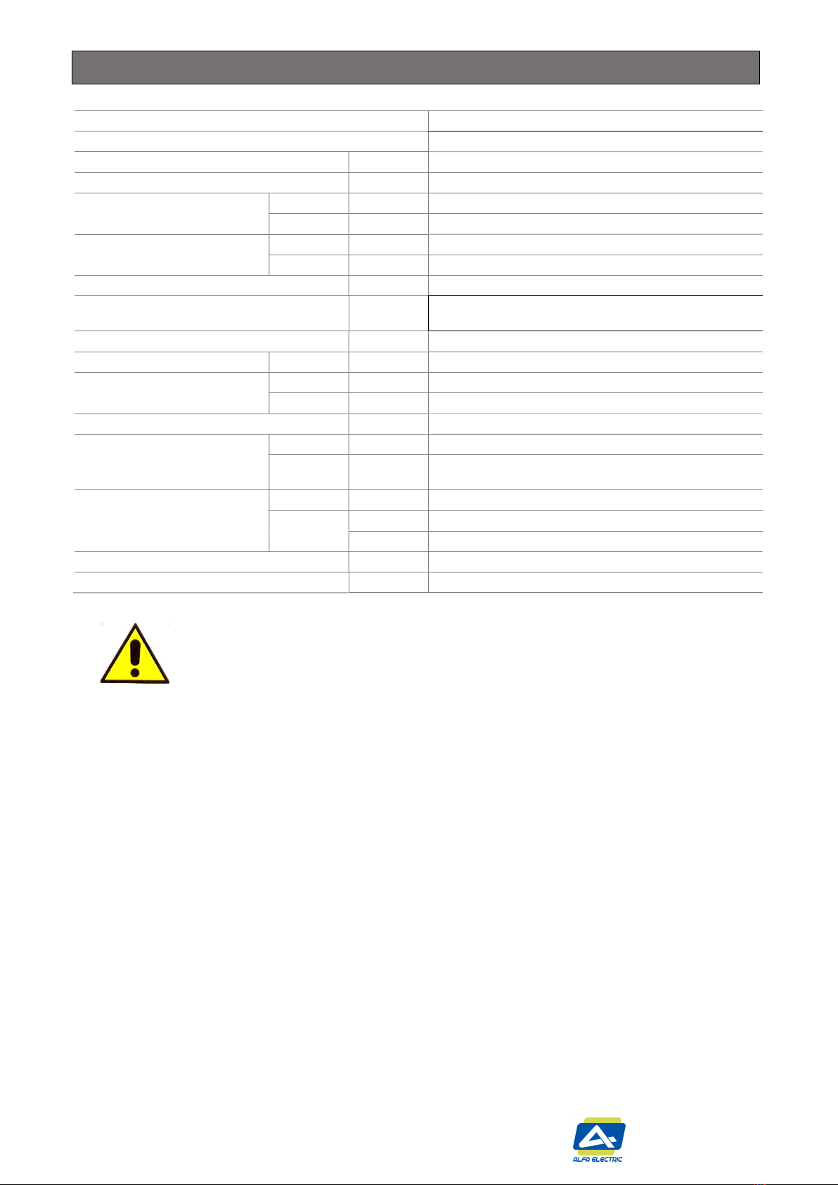
CONTROL TYPE ARTICLE CODE
Digital thermostat with alarms AVE400.432
FEATURES Unit
Power supply V | ph| Hz 400 | 3 | 50 / 460 | 3 | 60
Cooling capacity EN14511 A35-A35 W 3800/3980
A35-A50 W 2800/3160
Absorbed electric
power EN14511
A35-A35 W 2200/2320
A35-A50 W 2600/2750
Rated current A 2.7 / 3.0
Motor circuit breaker / Delayed pre fuse
(advised) A 16
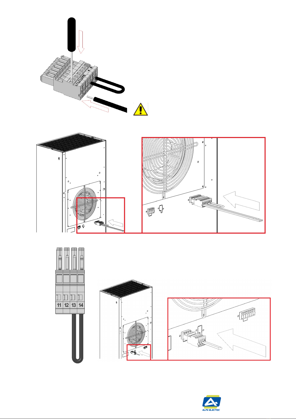
Electrical connection - connector
Air flow rate (free blow) enclosure m3/h 860/950
Operating temperature ambient °C (°F) +5 |+55 (+41|+ 131) / +5 |+50 (+41|+ 122)
enclosure °C (°F) +20 |+45 (+68/+ 113)
Refrigerant - | g R134a | 1000
Protection degree EN60529/1
ambient - IP34
enclosure - IP54 (when installed on enclosure with the same
protection degree)
Design
casing - Galvanised sheet steel
cover - Galvanised sheet steel powder coated RAL7035
- Stainless steel AISI304 for version with code ending 0X
Weight kg 76
Conformity / Certifications - CE
WARNING
Safety of AIR CONDITIONER is warranted only by proper use of these instruction which must be kept.
Installation must be done by qualified personnel only after enclosure power supply disconnecting.
Before any operation, switch off the power supply.
The appliance is classified as not accessible to the general public
The air conditioner is not to be used by persons (including children) with reduced physical, sensory or mental capabilities,
or lack of experience and knowledge, unless they have been given supervision or instruction.
Children being supervised not to play with the air conditioner.
The air conditioner must be installed in accordance with national wiring regulations
Upstream of the electrical connection, an efficient disconnection system must be provided in compliance with the
standard
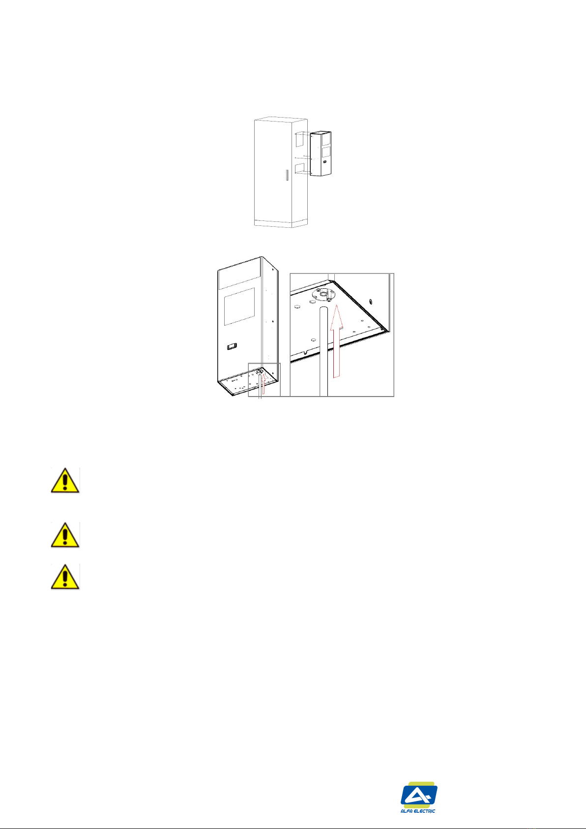
Internal and external components of electrical enclosure don’t have to affect the proper installation of air conditioner.
Inside of electrical enclosure there must not be components that could affect the proper ventilation.
Provide a proper fixing of the electrical enclosure to the floor to prevent accidental tipping due to the supplementary
weight of installed AIR CONDITIONER.
Installation position of AIR CONDITIONER must be selected to ensure good ventilation. Take care that any internal/external
components of enclosure don’t obstruct air passage. (see section 2.2 GENERAL CHECKS BEFORE INSTALLATION)
The heat loss of the components installed inside of the electrical enclosure must be lower than useful cooling power of the
AIR CONDITIONER.
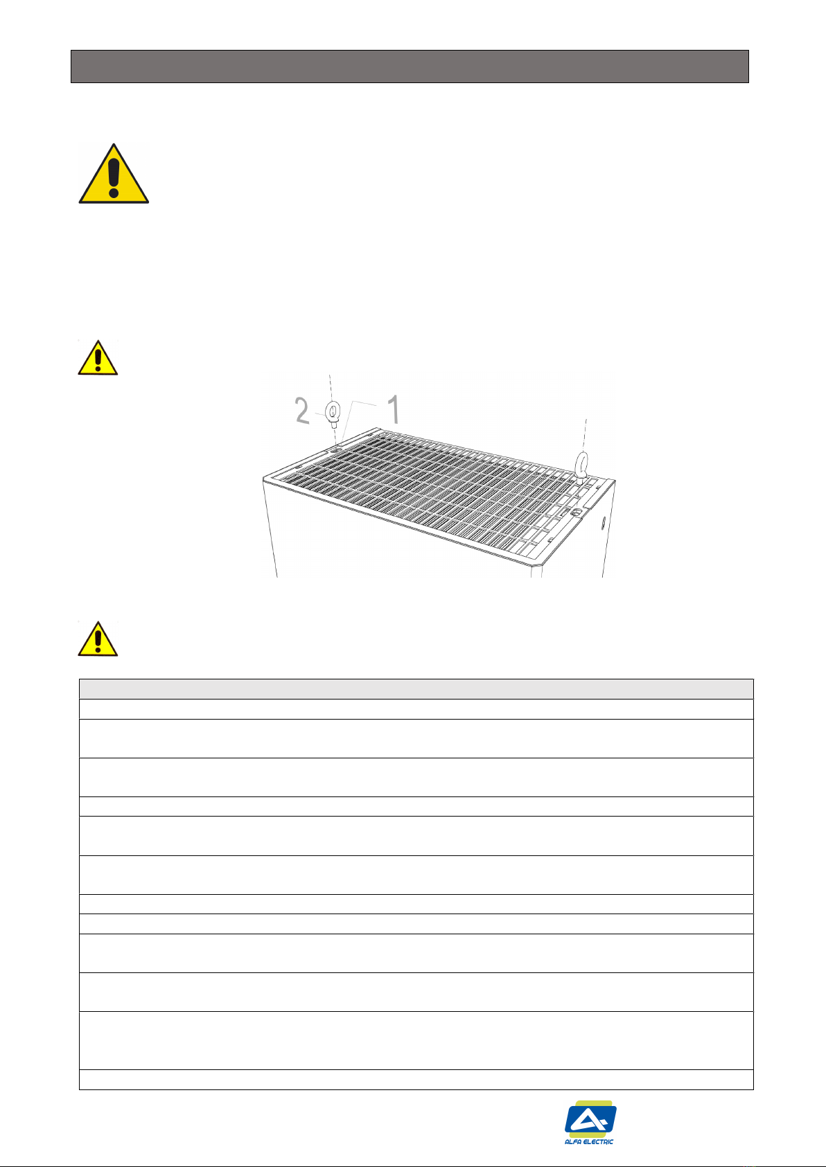
AIR CONDITIONER must be handled in upright position and protected against accidental tipping over.
Do not modify the AIR CONDITIONER structure if it is not specified in these instruction or associated instructions.
During transportation of enclosures with installed air conditioner a proper bracket must be used to support the cooling
unit weight.
Install only original spare parts and accessories.
Protection against access to live parts must be warranty by installer.
The supply connector of the AIR CONDITIONER must only be connected and disconnected when electrical enclosure is
electrically disconnected.
Follow all technical data shown in this manual