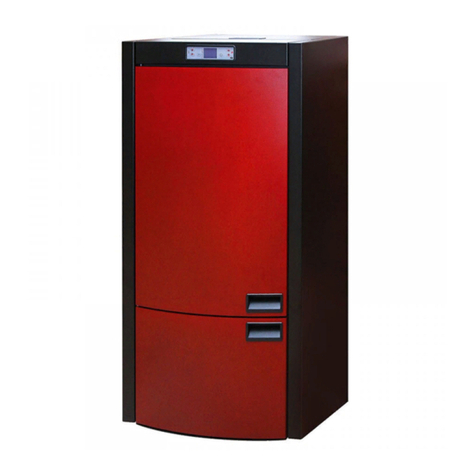
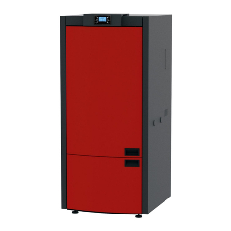
Alfa Plam Grande 37 Lux User manual

1612037
A.D. METALNA INDUSTRIJA VRANJE
1 Radnicka Str
PELLET BOILER
Grande 37 Lux
Instruction for use, maintenance and installation
This product meets the requirements of the Ecodesign Directive in terms of efficiency and air pollution level, in
order to contribute to the reduction of energy consumption and negative environmental impact.
ENG_V.1.0

DEAR CUSTOMERS!
Thank you for purchasing the Grande 37 Lux boiler. Please read the entire instruction carefully before installing and
commissioning your Grande 37 pellet boiler. Alfa Plam A.D. heating appliances (hereinafter referred to as "pellet boilers" or
"boilers") have been designed, manufactured and tested in accordance with the requirements of the applicable European
Directives on safety standards.
These instructions are intended for end users, installers and technicians authorized for operations on Grande 37 pellet
boilers. If you have any questions regarding the instructions or need any explanation, please directly contact the
manufacturer or an Alfa Plam authorized vendor.
Printing, translation or reproduction, as well as partial, of these instructions is only possible with the written permission
of Alfa Plam. The boiler uses pellets as fuel. It operates automatically by dosing the pellet with a helical worm conveyor from
the pellet tank, which is part of the device placed above the boiler part of the appliance. The pellet tank is filled from above
through the designated lid. Make sure that the boiler is properly dimensioned with respect to the heating system and energy
requirements of the facility. The appliance should be connected and commissioned by a person authorized by Alfa Plam.
The flame that develops in the boiler during normal combustion of wood biomass releases just the amount of carbon
dioxide (CO2) that would be released by natural wood decomposition. The amount of CO2formed during combustion or
decomposition of the wood corresponds to the amount absorbed by the tree during its life cycle and turned into oxygen and
carbon. Using non-renewable energy sources (coal, fuel oil, gas), unlike energy sources based on wood, much larger amount
of CO2is released to the air. It builds up over the years and contributes to enhancing the greenhouse effect. The principle of
clean combustion meets all requirements of preserving the environment, and Alfa Plam has devoted all its development and
activities to fulfilling this goal.
CAUTION
-The minimum installed power of the heating system must not be less than 65% of the boiler’s rated of the boiler, and
the maximum power of the system must not exceed 100% of the boiler’s rated power.
-The flue connected to the boiler must meet the requirements set in the user manual.
-To connect the appliance to the flue, do not use flexible hoses instead of flue pipes.
- Regular maintenance and care, such as cleaning the boiler, flue pipes and nozzles (pipes), are important for safe
operation, and especially for effectiveness and maintenance value of the boiler.
- Do not perform any unauthorized modification to the appliance, as any unauthorized modification will void the warranty.

Table of contents:
1. PURPOSE OF THE INSTRUCTION ........................................................................................................1
2. MANUFACTURER’S RESPONSIBILITY.................................................................................................. 1
2.1. MAIN USER RESPONSIBILITIES....................................................................................................... 1
2.2. REQUIRED GENERAL STANDARDS...................................................................................................1
2.3. HARMONIZED STANDARDS: ............................................................................................................1
2.4. TRANSPORTING AND MOVING THE PELLET BOILER .......................................................................1
2.5. INSTALLER’S RESPONSIBILITY .......................................................................................................2
3. INSTALLATION .................................................................................................................................... 2
3.1. SET UP ............................................................................................................................................ 2
3.2. FLUE GAS EXHAUST........................................................................................................................ 3
3.3. AIR SUPPLY.....................................................................................................................................6
3.4. CONNECTION TO THE POWER SUPPLY............................................................................................6
4. NON-RETURN VALVE........................................................................................................................... 7
4.1. MIXING VALVE.................................................................................................................................7
5. FIRST BOILER COMMISSIONING ......................................................................................................... 8
6. SAFETY WARNINGS ............................................................................................................................ 8
6.1. SAFETY WARNINGS FOR SERVICE PERSONELL...............................................................................8
6.2. SAFETY WARNINGS FOR USERS .....................................................................................................8
7. INSTRUCTIONS FOR SAFE BOILER STARTING AND SAFE CLEANING................................................... 9
7.1. REGULAR MAINTENANCE AND CLEANING OF THE BOILER .............................................................9
7.2. INSPECTION AND COMPONENTS NEEDING MAINTENANCE .......................................................... 10
7.3. ADDITIONAL MAINTENANCE ......................................................................................................... 10
8. IMPORTANT SAFETY INFORMATION .................................................................................................11
9. PELLET QUALITY IS VERY IMPORTANT .............................................................................................11
9.1. PELLET STORAGE.......................................................................................................................... 11
10. BOILER CONTROL SYSTEM ............................................................................................................... 11
10.1. Electrical connection diagram .......................................................................................................12
10.2. Touch screen control panel (display) –commands and functions Start screen –display 1/2 ........12
10.3. Menu............................................................................................................................................. 14
10.3.1. ON/OFF Menu........................................................................................................................ 15
10.3.2. Settings Menu ....................................................................................................................... 15
10.3.3. Power .................................................................................................................................... 15
10.3.4. Customization Menu.............................................................................................................. 15
10.3.5. Information Menu .................................................................................................................. 16
10.3.6. Chrono Menu ......................................................................................................................... 17
10.4. Boiler ignition and function phases ...............................................................................................17
10.5. Possible problems and solutions...................................................................................................18
11. INFORMATION ON BOILER DISPOSAL ............................................................................................... 20
12. TECHNICAL CHARACTERISTICS OF THE GRANDE 37 LUX PELLET BOILER........................................ 20
13. GRANDE 37 LUX BOILER DIMENSIONS.............................................................................................. 21
14. GRANDE 37 Lux PELLET BOILER HYDRAULIC INSTALLATION DIAGRAM ...........................................22
14.1. Pellet boiler hydraulic installation diagram (radiator heating)........................................................22
14.2. Pellet boiler hydraulic installation diagram (radiator and floor heating)......................................... 22
14.3. Pellet boiler hydraulic installation diagram (accumulation tank) ................................................... 23

1
1. PURPOSE OF THE INSTRUCTION
The purpose of this Instruction is to instruct the user to take all necessary safety precautions and all the necessary
actions which will guarantee proper and safe use of the heating appliance.
AMENDMENTS
This Instruction takes into account all the advanced technology existing at the time of placing the pellet boiler on the
market.
The Instruction does not apply to the products already on the market accompanied by appropriate technical
documentation, and cannot be considered incomplete or inadequate after each change, adaptation or application of new
technologies on newer products.
Carefully read and study the contents of this booklet. All information presented in this booklet should be considered
necessary for proper installation, use and maintenance of your boiler.
Carefully store the Instruction in a safe place. This Instruction for use, maintenance and installation is considered an
integral part of the pellet boiler.
If the boiler is sold to a third party, this Instruction must be delivered together with the boiler.
If you lose the Instruction, you can request a new copy from the manufacturer or an authorized vendor.
2. MANUFACTURER’S RESPONSIBILITY
By delivering this Instruction, Alfa Plam a.d. disclaims any criminal or penal liability for direct or indirect causing of:
accidents and/or damage occurred due to non-compliance with standards and notes contained in this Instruction;
accidents and/or damage occurred due to improper or incorrect use by the user;
accidents and/or damage occurred due to modifications or maintenance without authorization from the
manufacturer Alfa Plam a.d.;
insufficient maintenance;
unforeseen situations;
accidents and/or damage occurred due to use of non-original or inappropriate spare parts.
Installations is solely within the responsibility of the installer.
2.1. MAIN USER RESPONSIBILITIES
The boiler user must be an adult and responsible person.
Make sure that children do not approach the boiler while in operation, with the intention of playing.
Children must not approach the boiler while in operation with the intention of playing. This appliance can be used by
children aged 8 and older and persons with reduced physical, sensory or mental abilities, if they are supervised by an adult
who is familiar with the instructions for use. Boiler cleaning and maintenance cannot be performed by children without the
supervision of an adult.
2.2. REQUIRED GENERAL STANDARDS
Grande 37 Lux product has been manufactured in accordance with the following standards:
2006/42/EC MACHINERY DIRECTIVE
2014/35/EU LOW VOLTAGE DIRECTIVE
2014/30/EU ELECTROMAGNETIC COMPATIBILITY DIRECTIVE (EMCD)
2011/65/EU Restriction of the use of certain hazardous substances (RoHS Directive)
2009/125/EC Ecodesign Directive
2.3. HARMONIZED STANDARDS:
- EN 303-5;
- EN 50581;
- EN 61000-6-2;
- EN 61000-6-3;
- EN 60335-1;
- EN 60335-2-102;
- EN 62233;
- Commission Regulation (EU) 2015/1189;
2.4. TRANSPORTING AND MOVING THE PELLET BOILER
Take care of own safety when moving the boiler. Prior to transporting and moving the pellet boiler, which should be done
with maximum safety precautions, make sure that the load capacity of the cart is sufficient to lift the boiler. Avoid sudden
movements and/or improvised methods of moving the boiler. Boiler handling in terms of lifting, shifting and moving from one
place to another can be done by rod brackets threaded on one end. These rod brackets (4 pieces) are screwed on designated
points on either side of the boiler (Figure 1). Four men are required for this operation. Boiler brackets are delivered with the
boiler!

2
Figure.1 Moving the boiler with the bracket
CAUTION
GATHER ALL PACKAGING MATERIAL AND KEEP IT AWAY FROM THE REACH OF CHILDREN. PARTS OF PACKAGING
MATERIAL (BAGS, FOILS, STYRENE, ETC) REPRESENT A CHOKING HAZARD.
2.5. INSTALLER’S RESPONSIBILITY
The responsibility of the installer is to verify the correctness of installation, air supply and all the conditions that are
required for the installation of pellet boiler.
The responsibility of the installer is to verify compliance with legal regulations in the place where the boiler is installed.
The pellet boiler must be used in accordance with the Instruction for use, maintenance and installation, and with respect
to the safety standards set by regulations in force at the place where the boiler is installed.
Installer’s obligations are defined by the SRPS Standard 10683. Installers should check:
the type of the appliance to be installed,
the suitability of the space for appliance installation, i.e. the minimum dimensions of the space where the pellet
boiler is to be installed,
compliance with the regulations regarding the outlet of flue gases set in the instruction provided by the heating
appliance manufacturer,
inner diameter of the flue, the flue material, whether it is straight and correct and whether its free from clogging,
flue height and possible vertical extension,
existence and corresponding resistance of the flue caps,
possibility of outside air supply,
possibility of simultaneous use of heating sourced with other connected existing appliances.
If the above is provided, you can start the installation. Follow the manufacturer’s instruction carefully, as well as existing
safety norms and standards for fire protection.
After the first boiler commissioning, inspect the operation during at least 30 minutes in order to check whether all
requirements have been met.
After finishing the installation, the installer should provide the customer with the following documents:
Instruction for use, maintenance and installation supplied by the manufacturer (if not included with the boiler),
documents required by applicable regulations,
the installer should train the customer on how to use the appliance, how to perform regular maintenance and
cleaning.
3. INSTALLATION
The customer is solely responsible for installation works at the place where the boiler is being installed.
Prior to starting the installation, the installer should make sure all safety requirements have been met, in particular:
Check if the pellet boiler installation regulations meet the local, national and European standards.
Comply with all requirements from this document.
Check if the pipes and lines for air supply correspond to the installation type.
Do not perform temporary electrical connection with inappropriate cables.
Check the electrical installation earthing.
Always use personal protective equipment and adhere to all prescribed safety measures.
Always leave sufficient space for maintenance works.
Measure the flue gases emission upon completion of the installation.
3.1. SET UP
It is advisable to remove packaging material of the pellet boiler at the place where the boiler is to be installed.
If the adjacent walls and floors are made of materials that are not heat-resistant, it is necessary to ensure adequate
protection and use of non-combustible insulation materials.
To protect the floors from combustible materials, insert a 3 to 4 mm thick metal plate under the boiler with the front side
at least 30 cm longer than the depth of the boiler.
The pellet boiler must be installer in accordance with the drawing determining the distance from the walls (Figure 2).
Threaded rods

3
Figure 2: Minimum distance of the boiler from the walls
If the pellet boiler is installed in a boiler room with other devices that take in air (other boilers, various types of suction
fans, etc.), make sure that the volume of air entering the room is sufficient to guarantee safe operation of the boiler.
If the flue passes through the ceiling it must be sufficiently insulated with coating of non-flammable insulation material.
After the pellet boiler is set in place, level it with adjustable legs (bring it to a horizontal position).
CAUTION
DO NOT CONNECT the flue gas exhaust system to:
a flue used by other heating appliance (boilers, furnaces, fireplaces, etc.),
an air outlet system (from hoods, suction fans, etc.)
CAUTION
Do not install barriers for flue gas flow regulation!
The Ø80 mm flue pipe connection of the pellet boiler to the flue must have the following features:
total length of maximum 5 m (in case of a longer connection, the connecting pipe diameter must be Ø130 mm),
each flue knee of 90˚reduces the total flue pipe length by 1 m,
each flue knee should have a cleaning cover,
the flue pipe joints must be sealed.
CAUTION
If the resistance in the exhaust system is too high (numerous knees, inappropriate terminations, bottlenecks, etc.), the
flue gas outlet is not guaranteed and it is necessary to increase the connecting pipes and knees to greater dimensions, i.e. to
Ø130 mm. Also, when the flue does not provide proper flue gas outlet, it may cause malfunctions and consequently activate
the alarm in the Grande Lux boiler. It is recommended to have the flue inspected by a professional before installing the
Grande Lux 37 boiler.
The system for flue gas extraction from the boiler operated at a vacuum generated in the combustion chamber and the
faint pressure in the Ø80 mm flue pipe. Therefore, make sure that the flue pipe is completely sealed.
Carefully analyze the position and condition of the space through which the flue passes. If the flue pipe passes through a
wall and/or roof it should be suitably insulated in accordance with the safety regulations for fire protection.
Make sure that the room with installed pellet boiler has a sufficient amount of air guaranteeing proper combustion. The
outside air supply pipe should have a minimum outer diameter of 110 mm and a maximum length of 10 m. For every 90˚
knee, the maximum length is reduced by 1 m. If it’s too long, increase the diameter of the air supply pipe.
If a grate is fitted on the façade, the surface of the air supply port must be at least 100 cm2or larger.
The device operates on 220-230 V, 50 Hz voltage. Make sure that the electrical cables do not pass under the boiler, that
they are placed away from heated surfaces and that they do not come into contact with sharp objects that may damage
them. If the pellet boiler is under increased voltage, the durability of electrical components will be greatly reduced.
CAUTION
Do note remove the plug from the socket in order to switch off the boiler until the flame in the boiler is extinguished.
Otherwise, the boiler may be heavily damaged and the proper operation may be disturbed.
3.2. FLUE GAS EXHAUST
The flue gas exhaust must be in accordance with the applicable regulations. Do not connect the flue pipe of the boiler to
the flue with other heating appliances connected (Figure 3). The flue gas exhaust must not end in closed and/or in semi-
enclosed rooms, such as garages, narrow passageways, hallways, sub-corridors, etc. After connecting the boiler to the flue,
an authorized chimneysweeper should check if there are any damages in the connection and whether the connection is
properly sealed. If the flue is not suitable, it must be executed in accordance with the foregoing requirements (item 3.1).
Figure 3
YES
NO

4
CAUTION
The flue should be earthed in accordance with the applicable regulations. (Earthing is legally defined and
regulated.)
The earthing should be independent of the heating appliance.
When it comes to the dimensions and material, the flue pipe must meet the SPRS 9615-9731 and SRPS 10683 –EN1856-
1 standards.
Flue pipes which are poorly maintained or made of improper materials (asbestos, galvanized sheet metal, porous
materials) do not comply with applicable regulations and adversely affect the operation of the boiler.
Flue gases can be off-let via conventional flue (see figure below) if the following requirements have been met:
Check whether the flue has been properly maintained. Contact the chimneysweeper for proper maintenance and/or
repair.
The flue gases can be off-let directly to the flue only of fitted with an inspection eye and if the flue dimensions do
not exceed 20 x 20 cm i.e. the diameter does not exceed 20 cm.
If the flue exceeds the dimensions, insert appropriately insulated stainless steel pipe (of corresponding diameter)
into it.
Make sure that the flue connection is properly sealed.
Avoid contact with flammable materials (ember) and install flameproof insulation.
When using fittings for connecting the pellet boiler to the flue, make sure to install flue knees with a cleaning eye (Figure
4). Using a knee with a cleaning eye enables regular cleaning without the need for dismantling the pipe. The exhaust gases in
the flue connection are under slight pressure, therefore it is necessary to check that the cover for ash cleaning is completely
hermetically sealed and closed tightly after each cleaning. Make sure that everything is properly put back in its place and
check the condition of the seals.
Figure 4: Cleaning element
The flue pipes should be connected so as to have their narrow connection element always turned upward (Figure 4).
We recommend not making long horizontal sections for the flue connection. If there is no other possibility, the flue pipes
should not have a downward slope, but upward to at least 5%. The horizontal section should not be longer than 2 meters.
Direct boiler connection to the flue with a straight flue pipe longer than 1 meter in length is not recommended.
Figure 5 Figure 6
The maximum allowed length of flue pipe with diameter of 80 mm to its point of entering the flue is 5 m. After that, the
diameter of a flue pipe must be increased to 120 –130 mm. Each flue knee accounts for more 1 m length. For example, if
there are three flue bends of 80 mm diameter, the length of the flue pipe of 80 mm diameter is changed by 3 m. You may
place only another 2 m of a straight pipe to the entrance of the flue in order to get maximum 5 m length of the flue pipe of 80
mm diameter. After that, it must be enlarged, led back to flue pipe or introduced a flue of a greater diameter, 120 –130 mm.
Make sure not to use flue bends of a sharp 90º angle. They must be of a certain radius or made in segments. A sharp flue
bend increases resistance of the smoke flow through the bend.
-Each flue knee must be fitted with a cleaning door.
-The joints between the connection pipes must be sealed.
-Use a connection of Ø100mm for greater distance. In this case, the allowed length is up to 8m.
INSULATION AND DIAMETER OF THE ROOF OPENING
After you have determined the final position of the boiler, make an opening for the passage of the flue pipe. It depends on
the installation method, pipe diameter and type of walls or roof through which the flue pipe is run. The insulation should be
done using mineral insulation material (glass wool) of nominal density greater than 80 kg/m3.
The ideal vacuum depends primarily on the lack of barrier such as contractions and/or angular connections. It is
recommended to have the flue knees at 30˚, 45˚ and 90˚. The 90˚flue knee should be three-part knees (Figure 7).
YES
NO
Flue gas direction
5%
or more

5
In any case, make sure that the length of the initial vertical part of the flue pipe is at least 1.5 meters. Proper exhaust of
flue gases is guaranteed in this way only.
Figure 7
AISI 316 steel flue with double insulated chamber, material
resistant to 400 ° C. Optimal efficiency 100%
Waterproof flue with double insulated chamber and outer
casing of light concrete. Optimal efficiency 100%
Traditional clay flue with indents. Optimal efficiency 80%
Do not use flue pipes with rectangular cross section with
ratio different from the plan. Efficiency of modest 40%

6
Flue –position and distance
3.3. AIR SUPPLY
The combustion air must be supplied to the room with the boiler. The room must be continuously aired.
The fresh air opening must be at the bottom of the room and must let in the air.
A) Combustion air supply by pipeline through basements. This connection option preheats the combustion air, which is
useful for good and clean combustion. Installation of pipelines in the basement is simple.
B) Combustion air supply through basements. The combustion air is preheated. The basement space must be separated
from the ventilation system of the house and open to the outside. Avoid high levels of dust and moisture.
V) Combustion air supply from above. Air supply from above can only be performed with tested flue systems.
In this case, you must calculate the dimensioning of the flue!
D) Combustion air supply directly from outside. If the air is supplied directly through the outer wall, the combustion air is
only slightly preheated, which is unfavorable for clean combustion. In this case, there is also a risk of condensation!
NOTE: We do not recommend these versions of the air supply! However, if you use these options, consult a qualified
professional.
The room with the heating appliance must have a sufficient supply of fresh air. If the windows and doors are hermetically
sealed or there are air extracting devices such as a hoods, hair dryers, fans, etc. located in the room with the boiler,
combustion air (fresh air) must be supplied from outside. In any case, this should be discussed with the competent
chimneysweeper before installing the boiler.
Figure 8- Fresh air supply to the room with the boiler
3.4. CONNECTION TO THE POWER SUPPLY
The appliance must be connected to the power grid. Our boilers are equipped with an electrical cable for medium
temperatures. The power cable must be replaced if damaged, so contact our authorized service.
Before starting the works on the electrical connection, take care of the following:
Whether the electrical installation characteristics correspond to the information on the boiler.
The flue gas exhaust must be earthed in accordance with local regulations. (The earthing is required by law.)
The power cord must not in any case be exposed to the temperatures of over 80˚C. If you want to connect the boiler
directly to the power grid, you must install a two-pole switch, suitable for the mains voltage in accordance with the
applicable regulations, with contact spacing of at least 3 mm. The green-yellow earthing conductor must be
disconnected in the switch. The two-pole switch must remain accessible after finishing the installation of the boiler.
Connection to the power supply
The pellet boiler should be connected to the power grid. The power connection cable is 3 m long, white in color and
marked “220 V”. The other connection cable is black, intended for connection of the circulation pump and marked “Pump”.

7
Figure 9
White –Boiler power (220 V)
Black –Circulation pump
If the power cable is damaged, replace it. Replacement must be done only by an authorized person.
The power connection should remain available after the final installation of the pellet boiler.
CAUTION
You must measure the flue gas emission after installing the boiler.
4. NON-RETURN VALVE
The installation of the non-return valve in the hydraulic heating installation is mandatory.
The function of the non - return valve is to prevent cooling of the water in the boiler and condensation in the boiler
and flue pipes. The condensation can occur until you have spent 2 –3 fuel tanks.
The condensation in the boiler is normal for the first ignition.
The non –return valve is installed at the outlet of the pump, behind the pump, not in front of the pump. Take care of
the valve installation direction. Also, when purchasing the valve, check if it is placed on horizontal line, on vertical line or as
inclined, because there are valves that are installed only horizontally or only vertically, or they are universal ones.
Check if the valve is easily opened (check with a finger) so that it could be opened with the pump’s power.
The non-return valve is placed behind each pump. If there are multiple pumps, you
will need multiple non-return valves.
The boiler connections are 1". So the non-return valve should be 1", or larger.
The warranty shall be void if the non-return valve is not installed!
The non-return valve installation diagram is as follows:
1. Grande 37 Lux boiler,
2. Circulation pump,
3. Non-return valve
4.1. MIXING VALVE
Firstly, the reduced thermal power of the boiler will be used due to the high thermal power of the boiler, it is necessary to
fit the hydro installation with a built-in three-way mixing valve to avoid condensation of the boiler. This will extend the life of
the boiler.
A mixing valve is required for floor heating installations. We recommend special thermostatic valves for floor heating that
regulate the temperature of the water entering the floor up to 50ºC. If there is no such thermostatic mixing valve, the
temperature of the water entering the floor system must be regulated in some other way. It is the job of the designer and
installer.
The mixing valve should be 1".
white cable
boiler power
black cable
circulation pump

8
5. FIRST BOILER COMMISSIONING
The first boiler commissioning must be performed exclusively by an authorized person, otherwise the warranty becomes
invalid.
INSTRUCTIONS FOR THE SAFETY OF PERSONS, ANIMALS OR PROPERTY
We want to draw attention of installers to some procedures to be followed so that proper installing of pellet boilers could
be guaranteed. It is necessary to comply with the required standards, but they themselves are not sufficient. For detailed
information, read the rest of the instructions for use, maintenance and installation.
Connect the pellet boiler to the power grid.
Do not allow children and animals near the boiler.
Only use pellet with guaranteed quality and do not use other fuels.
Inform all users of any possible risks and hazards, then inform them on how to use the pellet boiler.
If the boiler is placed on a wooden floor, insulate it appropriately.
The pellet boiler works in such a way that some vacuum is generated in the combustion chamber, so make sure that the
flue gas outlet is thermally sealed.
The paint releases unpleasant odors at first commissioning (at least 1 hour of operation of the boiler), so it is necessary
to ventilate the room well.
6. SAFETY WARNINGS
6.1. SAFETY WARNINGS FOR SERVICE PERSONELL
In addition to the general safety regulations, the person engaged in maintenance should also observe the following:
Always use safety and personal protection equipment as determined by the Directive 89/391/EZ.
Make sure that the power supply is disconnected before beginning any activity.
Always use proper tools.
Before starting any intervention on the boiler, especially before coming into contact with the boiler make sure that
the boiler and ashes in it are cold.
THE PELLET BOILER IS CONSIDERED UNUSABLE EVEN IF ONLY ONE SAFETY DEVICE IS DEFECTIVE, IMPROPERLY
REPAIRED OR IF IT IS NOT WORKING!
Do not make any modifications for any reason, except with the permission of the manufacturer or an authorized
person.
Always use only the original spare parts. Do not wait for the boiler parts to be worn out before replacing them.
Replace the worn-out parts before they stop working completely, thus preventing damage due to sudden failure of a
component, which may seriously endanger the safety of persons and/or your property.
Clean the firebox and the space underneath it when cleaning the ashes.
6.2. SAFETY WARNINGS FOR USERS
The room where the pellet boiler is or will be installed should be designed in accordance with local, national and
European standards.
The pellet boiler is a combustion device. During operation, some parts may heat up to very high temperatures.
The pellet boiler is a class C1 appliance designed to burn only wood pellets (pellets with a 6 mm diameter, maximum 30
mm in length and of moisture content of up to 10%), i.e. C1 fuel (wood pellets) in accordance with the EN Standard 14961-2.
CHILDREN MUST NOT APPROACH IT OR PLAY WITH BOILER WHILE IN OPERATION!
The following precautions are recommended during operation of the boiler:
DO NOT approach or touch the combustion chamber door during the boiler operation. There is a RISK OF BURNS.
DO NOT approach or touch the flue pipe during the boiler operation. There is a RISK OF BURNS.
DO NOT perform any cleaning of the heating installation during the boiler operation.
DO NOT open the firebox door during the boiler operation, it will function properly only when the door are
hermetically closed.
DO NOT remove the ashes during the boiler operation.
DO NOT allow children and animals to approach the pellet boiler.
FOLLOW THE INSTRUCTIONS FROM THIS DOCUMENT
Follow the following advice for correct use of the boiler:
Only use the fuel recommended by the boiler manufacturer.
Follow the maintenance instructions.
Clean the firebox after spending the pellet tank (3 to 14 days, only when the boiler and the ashes are cold).
DO NOT use the pellet boiler in case of a failure or other defects, unusual noises and/or if you suspect there has
been a failure. Contact the authorized service IMMEDIATELY.
DO NOT pour water on the boiler or extinguish fire in the combustion chamber with water.
DO NOT lean on the boiler since it may not be sufficiently stable and could be capsized.
DO NOT use the pellet boiler as support or for supporting other object. Do not leave the pellet tank cover open.
DO NOT touch the painted parts of the boiler during operation.
DO NOT use wood or coal for the pellet boiler, only use pellets of the following characteristics:
- dimensions: 6 mm diameter
CAUTION
CAUTION

9
- max. length: 30 mm
- moisture content: do 10%
- firewood value: min. 16.9 MJ/kg, or 4.7 kWh/kg
- ash content: below 0.7%
DO NOT use the boiler for burning waste.
Always make sure there is maximum safety.
7. INSTRUCTIONS FOR SAFE BOILER STARTING AND SAFE
CLEANING
DO NOT use heating oil, kerosene or similar derivatives and other flammable liquids to start the boiler. While the boiler is
in operation, keep these liquids and other liquids away from it.
Make sure that the pellet boiler is properly installed and that it is not moving.
Make sure that the firebox is tightly closed and will remain closed during the boiler operation.
Remove the ashes only when the pellet boiler is cold.
Do not use abrasive cleaners to clean the pellet boiler.
7.1. REGULAR MAINTENANCE AND CLEANING OF THE BOILER
Using a vacuum cleaner to vacuum ashes makes removing ashes from the boiler easier.
Before beginning any maintenance or a cleaning procedure, adhere to the following safety rules:
Turn the pellet boiler off before beginning any procedure.
Make sure that the ash is cold before beginning any procedure on the boiler.
Vacuum the ashes deposited in the combustion chamber at least once every ten days, i.e. after spending a pellet tank
(only while the boiler is cold) (Figure 11).
Open the front bottom door of the heat exchanger on the right side of the boiler and vacuum the interior once a month
(Figure 11) Always check if the boiler and ashes are cold.
Figure 10
This it the firebox for burning pellet (Figure 10). We recommend to inspect it before each cleaning and remove the ashes
from the firebox bottom and the combustion chamber.
The firebox is located in the so-called firebox bracket and is never pulled out of the firebox bracket during cleaning
(Figure 10a). Clean the space under the firebox by pulling out the slider at the bottom of the firebox bracket as shown in the
picture below and then use an ash vacuum cleaner or some other means to clean all the ash that has accumulated in the
space under the firebox. This cleaning should be done every 2 to 3 days.
Figure 10a

10
Figure 11
CAUTION
For any further information, contact the installer. The manufacturer does not have direct control over the work of
installers and cannot guarantee for any work done or for maintenance works.
The manufacturer does not in any case assume responsibility for damage caused by third parties
CAUTION
Make sure that the pellet boiler and ashes in it are cold.
After using the entire tank of pellets the combustion chamber must be cleaned by vacuuming and/or removing all debris
generated by pellet burning.
Incompletely burned pellets should never be returned to the pellet tank or disposed of in the container for ashes.
CAUTION
Open the upper right door daily or before each ignition and shake the handle of the
mechanism for chamber cleaning. This operation is of crucial importance in prevention of
ash-related tubes clogging and provision of safe and secure operation of the boiler!
CAUTION
Open the lower right door every 15 days and clean the right ashtray where the ash is
collected after cleaning the mechanism for chamber’s pipe cleaning. This operation should
be completed only when the boiler is cold.
7.2. INSPECTION AND COMPONENTS NEEDING
MAINTENANCE
CHECK THE ITEMS LISTED BELOW TO ENSURE PROPER OPERATION OF PELLET BOILERS. THESE PRECAUTIONS
ENSURE THE MAXIMUM OUTPUT OF THE BOILER AND THE TEMPERATURE OF THE SYSTEM:
Make sure that the pellet boiler and ashes are cold
For complete weekly cleaning or after 200 kg of used pellets (whichever is earlier) vacuum the ashes underneath the
firebox and from the combustion chamber. You can use a brush to clean the walls of the firebox.
GENERAL CLEANING OF THE BOILER AT THE END OR BEGINNING OF THE HEATING SEASON:
Make sure that the pellet boiler and ashes are cold. Turn the power supply to the boiler off.
Disconnect the power supply to the boiler after the end of the heating season. It is very important to clean and
inspect the boiler as described in this Instruction.
The door seal may become loose after some time, although it is attached with glue resistant to high temperature. To
reattach the seal, apply an adhesive resistant to high temperatures on the back of the seal. This way, the hermetic sealing of
the firebox door is guaranteed.
CONNECTION OF THE FLUE PIPE TO THE FLUE (should be cleaned at the end of each heating season):
Make sure that the pellet boiler and ashes are cold.
The flue pipe, the flue and the flue cap should be inspected and cleaned annually. To carry out the procedure
professionally, you should contact a chimneysweeper.
7.3. ADDITIONAL MAINTENANCE
Your pellet boiler is a source of heat for which only pellet may be used. Annual boiler maintenance can only be performed
by a person authorized by Alfa Plam a.d.
cleaning
opening the door

11
Regular annual service will preserve proper operation of the heating appliance, ensure its greater efficiency, keep the
warranty valid and extend the life of the appliance itself.
It is recommended to carry out the procedures described in the previous section at the end of the heating season. The
purpose is to inspect and ensure proper operation of all components.
8. IMPORTANT SAFETY INFORMATION
You have purchased the highest quality product.
The supplier is at your service for any information you may need. Proper boiler installation, carried out in accordance with
the attached instructions, is important for the prevention of any defect, risk or danger of fire.
The pellet boiler works on the basis of vacuum generated in the combustion chamber, therefore it should always be
ensured that the joints to the flue are sealed and tight.
CAUTION
In the event the flue catches fire, people and animals should immediately leave the area. Disconnect the power supply to
the mains immediately after that, or take out the plug out of the socket (only if you are not putting yourself at risk), and
contact the fire department.
CAUTION
For safety purposes and preservation of function of the pellet boiler, do not use finely chopped wood.
CAUTION
Do not use the pellet boiler to burn waste.
9. PELLET QUALITY IS VERY IMPORTANT
The pellet quality is very important!
The boiler is designed to use pellets. Considering that a variety of types and sizes of pellets are available on the market, it
is important to choose pellet that does not contains impurities, which is compact and does not generate dust (use pellet at
least according to the EN plus A2 European standard).
Consult the supplier on the type of pellet, which needs to be 3.15-4’ mm in size and have a 6 mm cross-section. Proper
operation of the boiler depends on the type and quality of the pellets.
The manufacturer is not in any way responsible for poor performance of the boiler due to the use of poor quality pellets.
If sawdust or small - decomposed pellets are placed in the funnel part of the boiler, i.e. in the pellet tank, they can block
the insertion of pellets. Such pellet can lead to malfunction of the gear motor driving the pellet feed mechanism or damage
the gear motor. If you see such a small, decomposed pellet at the bottom of the pellet tank, or at the bottom of the worm
conveyer when the tank is empty, vacuum it with a vacuum cleaner by passing the extended vacuum cleaner tube through
the openings of the pellet grate. Even better, when there is little pellet in the tank, vacuum the bottom of the tank every 1 to
1.5 months as described.
9.1. PELLET STORAGE
Pellets should be stored in a dry room that is not too cold. Cold and wet pellet (temperature about 5°C) reduces the
thermal power and requires increased boiler cleaning.
CAUTION
Persons with an impaired spine and pregnant women should avoid lifting bags of pellets.
The manufacturer waives all responsibility for any damage or improper operation of the boiler due to the use of low
quality pellets.
CAUTION
Pellets should be in accordance with the DIN 51731, DIN plus, Ӧ-Norm -7135 or other comparable European standards.
CAUTION
PELLETS MUST NOT BE KEPT NEAR THE BOILER. Leave a distance of at least half a meter.
When handling pellets, make sure that they are not spilled.
If you add sawdust in the pellet tank, it may block the system for dosing pellets.
10. BOILER CONTROL SYSTEM
The boiler is fitted with advanced control system which provides safe, efficient and reliable operation and maximum
functional efficiency of the boiler.
Its characteristics are:
simple setting an use,
simple and direct user functions,
reliable and flexible function software specially developed for pellet boilers,
advanced functions available for installers for adaptation of different configurations and installations.
CAUTION

12
10.1. Electrical connection diagram
10.2. Touch screen control panel (display) –commands and functions
Start screen –display 1/2
Start screen –display 2/2
YELLOW-
GREEN
POWER CABLE
FLUE GAS FAN
TURBULATOR REDUCER
PRIMARY AIR FAN
LIGTER
AUGER REDUCER
THERMOMETER
MANOMETER
PENDULUM REDUCER
PUMP
MICRO-SWITCH 1
MICRO-SWITCH 2
FLUE GAS
FAN
ENCODER
AUGER
MOTOR-
REDUCER
ENCODER
WATER BOILER PROBE
FLUE GAS PROBE
AIR FLOW
SENSOR
K400 DISPLAY

13
The screen display changes by swiping the finger horizontally across the screen.
Display 2/2 provides information on the work of certain components connected to the controller, by having the certain
connector element icon light green when the element is in function, and not lighting up, i.e. staying black when the element is
inactive. Subsequent connection of a component to the system will show in the listed components in this display.
Element
Description
Auger
Auger on/off
Pump
Pump on/off
Valve
Pendulum reducer on/off
V2
Room fan on/off
V3
Turbulator reducer on/off
A1
Heater-igniter on/off
A3
Pendulum reducer on/off
A5
Auger reducer blocked/not blocked
External Chrono
Chrono mode on/off
Lack of Pellet
Pellet lacking/not lacking
Room Thermostat
Room thermostat connected/not
connected
Flow Switch
Switch on/off
Quick display of main system functions is shown by swiping the finger vertically across the screen from top to bottom.
Function name
Description
Function
Season
Summer/Winter
Mode
Fuel type
Wood/Wood+Pellet/Pellet
Power
Power
Power range 1÷5
Chrono
Work mode
Daily/Weekly/Weekend
Errors (Alarms):

14
Error (alarm)
code
Error (alarm) description
Er01
Safety thermostat activated
Er02
Safety manometer activated
Er03
Extinguishing due to low temperature of flue gases
Er04
Extinguishing due to high water temperature in the boiler
Er05
Extinguishing due to high temperature of flue gases
Er07
Encoder error. No signal
Er08
Encoder error. Unable to adjust the number of revolutions
Er09
Water pressure too low
Er10
Water pressure too high
Er11
Error due to problems with the internal clock
Er12
Extinguishing due to ignition failure
Er15
Power outage longer than 50 minutes
Er16
Communication error RS485
Er17
Airflow regulator error
Er18
No pellet
Er25
Firebox cleaning motor error
Er26
Turbulator cleaning motor error
Er39
Airflow regulator failure
Er41
Minimum airflow in CHECK UP phase not reached
Er42
Maximum airflow reached
Er47
Auger encoder signal error
Er48
Unable to adjust the number of revolutions of auger motor
10.3. Menu
Enter the main menu by selecting the icons in the bottom start screen.
When there is a system error, the top right
corner shows the error code and symbol !
Pressing this section of the screen will open
the error window.
If the system works without problems, the top
right corner will show the symbol i

15
10.3.1. ON/OFF Menu
The ON/OFF menu enables the user to turn the appliance on or off by swiping the finger over the field (shown below),
while displaying the current appliance operating mode.
10.3.2. Settings Menu
The Settings menu shows the system variables that are necessary for its operation. The user can set the power by
selecting from the list of values from P1 to P5 or automatic setting, and set the maximum boiler temperature in the range of
40 ÷ 80°C.
We do not recommend setting the water temperature below 57ºC due to possible condensation of the boiler, nor over
75ºC.
10.3.3. Power
Menu for system combustion power setting in manual or automatic mode. In manual mode, the user can set the pellet
combustion power.
Power
Description
1-5(combustion power 1, 2, 3, 4, 5)
Power is set manually by choosing Power 1, 2, 3, 4 or 5
Auto
Power is set automatically by the system
10.3.3.1. Thermos tats
The menu that allows you to set the so-called set boiler water temperatures (Boiler Thermostat). The adjustable boiler
water temperature range is from 40°C to 80°C. By setting the temperature of the water in the boiler, the user sets the
operating condition of the boiler, i.e. the boiler will work at the set power until it reaches the set water temperature in the
boiler. When the set value of water temperature in the boiler is reached, the boiler enters the modulation state, i.e. continues
to operate at minimum power.
10.3.4. Customi zation Menu
Customization menu includes an overview of the control panel variables and accesses the system menu reserved for
service technicians and technical staff and is accessible by entering a 4-digit code.
10.3.4.1. Settin gs
There are several submenus within the setting icon.
Time and Date –This option allows you to set the day, month, year and hour.
Language –This menu allows you to change the language and offers 24 languages.
Remote Control –This option allows control via a room thermostat (SYTX4 or 2WAYS2). It must be activated beforehand
by setting a specific parameter. Remote control is not provided at the factory (OFF).
Summer-Winter –The functionality of the boiler is modified depending on the season.

16
Temperature Unit –This option selects the temperature display in degrees Celsius (°C) or Fahrenheit (°F).
10.3.4.2. Service
The service menu provides various information about system conditions.
Counters –this option makes it possible to read information on the number of boiler starts, the number of failed starts
and the operating time in normal operation mode, modulation and safety mode.
Secondary Information –shows the states of the boiler elements listed in the table below.
Contacts
Description
Evo Code
Installed electronics code display (577)
Appliance number
Not shown
Combustion fan
Current no. of fan revolutions per minute
Auger
Current no. of auger revolutions per minute
V2 outlet
Turbulator reducer operation status
V3 outlet
Primary air fan operation status
A1 outlet
Heater-igniter operation status
Valve
(Empty contacts)
A3 outlet
Pendulum reducer operation status
Pump
Pump operation status
A5 outlet
Auger reducer operation status
Airflow
Current flow in m³/h
Smoke temperature
Current temperature of exhaust gases in °C
Water temperature
Current temperature of boiler water in °C
IN2 inlet
Status of (digital) auger encoders’ contacts
IN3 inlet
Status of (digital) inlets 3 contacts
IN8 inlet
Status of (digital) micro-switches 2 contacts
IN9 inlet
Status of (digital) micro-switches 1 contacts
HV1 inlet
Status of thermostat contacts
HV2 inlet
Status of manometer contacts
Auger Calibration –menu for changing the feeding speed of the auger. The system has 15 calibration steps (from -7 to
+7; factory set to 0). The calibration effect is valid in operating mode and in modulation. Decreasing and increasing the steps
decreases and increases the calibrated auger speed.
Fan Calibration –menu for changing the speed of the flue gas fan. The system has 15 calibration steps (from -7 to +7;
the factory setting is 0). The calibration effect is valid in operating mode and in modulation.
Note: Do not calibrate the auger and fan without first consulting an authorized service center or the manufacturer's
representative.
Auto Power –this menu allows you to adjust the power of the exhaust gases only in automatic mode.
Manual Load –this option allows you to calculate the amount of pellets used in 10 minutes if the service technician has
enabled this by adjusting the parameters. The system must be off to activate this function.
10.3.4.3. System Menu
This menu allows access to technical settings. Access is password protected and is only allowed to authorized technical
staff.
10.3.4.4. Display menu
The control display parameters are set in this menu.
Option
Description
Brightness
Adjusting the brightness of the touch screen
Minimum brightness
Adjusting the minimum brightness of the display when it not used
Standby display
The display enters standby mode to save power after a period of inactivity
Control panel address
Access allowed to authorized technical personnel
Reboot control panel
Enables the control panel software restarting
Sound
Adjusting the sound emitted by the panel on/off
Delete error list
Option to delete the error history list. Access provided by authorized technical personnel
Node list
Displaying all devices connected to the control panel via Modbus
Wallpaper
Selecting the home screen background
Control panel info
Panel technical characteristics
10.3.5. Inform at ion Menu
The information menu shows the information on the current exhaust temperature (°C) and the current boiler water
temperature (°C)

17
10.3.6. Chrono M en u
This menu is used for setting the on/off time, i.e. the programmed boiler operation for precisely defined time periods. The
possible modes are daily, weekly and weekend mode. The selected mode appears in the upper left corner of the screen, and
the modes themselves or their times are changed by clicking on the pen below the mode name. During setting, the times are
red and thus inform the user that the change has not been saved.
10.3.6.1. Daily
The day of the week and the programmed time of switching the system on and off are selected. There are three time
ranges for each day. To set the boiler to work during the night, set the times as follows: Set the turn-on time of the boiler for
the previous day of your choice (e.g. 22:00) Set the turn-off time for the previous day at 23:59. Set the turn-on time for the
current day at 00:00. Set the turn-off time for the current day of your choice (e.g. 6:00).
10.3.6.2. Weekly
The set programs are the same for all days of the week. Each day has the option to set three time ranges.
10.3.6.3. Weeken d
This mode provides the option to select the time ranges Monday ÷ Friday and Saturday ÷ Sunday, and set the on and off
times.
10.4. Boiler ignition and function phases
The boiler is turned on by pressing the on/off in the menu in the lower left corner of the screen. After that, the following
functional states of the boiler are listed:
Check Up
The initial test of correctness on boiler input signal, probes and manometers is performed during the check up phase.
During this phase, the flue gases motor is working at maximum speed while the auger and the igniter are turned off. The
check up phase takes a few seconds and the ignition phase will start after a successful test.
Ignition
Ignition Phase is comprised of four consecutive sub-phases:
- Preheating phase
- Pellet preloading phase
- Fixed ignition phase
- Variable ignition phase
During the ignition phase, IGNITION is visible on display. There are no special signs for sub-phases on the display.
Ignition Preheating
During this phase, the igniter is being warmed up before the pellet feed starts. In order to achieve a successful pellet
ignition, the igniter should preferably already be warmed up at the time the pellet feed starts. In this phase, the igniter is
active and the auger inactive. Flue gases motor is working at lower speed to boost the igniter warm up.
Ignition Preload
During this phase, the initial pellet feed starts and the auger supplies a certain amount of pellet for ignition. During this
phase, the igniter, the auger and the flue gases motor are active.
Ignition –Fixed Phase
This phase lasts a fixed time period of 180 seconds and in case the ignition was successful before this phase ended it
will continue until the time expires and the boiler switches to stabilization phase. The igniter, the auger and the flue gases
motor are active during this phase.
Ignition –Variable Phase
This phase follows a fixed ignition phase. The duration of this phase varies from the moment of meeting the conditions
for ignition until the temperature of flue gases is 45°C. In case the ignition of the boiler is achieved before the phase time
Table of contents
Other Alfa Plam Boiler manuals
Popular Boiler manuals by other brands

VOKERA
VOKERA Mynute 12HE Installation and servicing instructions

Benchmark
Benchmark mCHP BoilerMate Design, installation and servicing instructions

Baxi
Baxi Combi 133 HE Plus Installation & servicing instructions

Wolf
Wolf CGB-75 instructions

Immergas
Immergas VICTRIX ZEUS 20 Instruction booklet

Varme
Varme VT100C user manual

Atmos
Atmos D15P instruction manual

Clifton Range
Clifton Range 1000 Series user manual

Potterton
Potterton Prorile Prima 30e user guide

thermital
thermital ACQUAHOME R BLU Series Installation and maintenance manual

Buderus
Buderus Logano plus GB312 Installation and maintenance instructions

Raypak
Raypak Xtherm 1005 Illustrated parts list