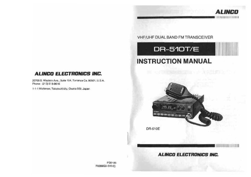
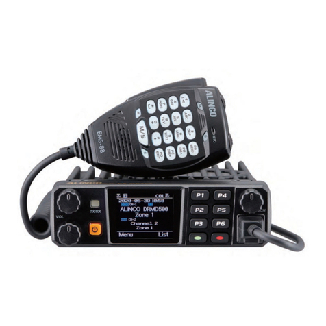
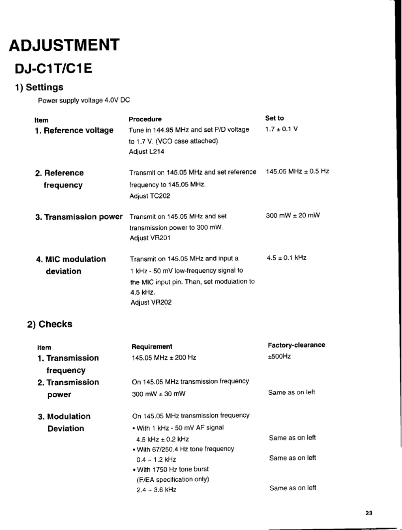
Alinco DJ-G29T User manual

ALINCO
222/902MHz
DUAL
BAND
FM
TRANSCEIVER
DJ-G29T
Instruction Manual
Thank you for purchasing your newAlinco transceiver. Please read this manual
carefully before using the product to ensure full performance, and keep this
manual for future reference as it contains information on after-sales service.
In
case addendum or errata sheets are included with this product, please read
those materials and keep them together with this instruction manual for future
reference.
ALINCO, INC.

2
NOTICE
I
Compliance
Information
Statement
NOTICEI Compliance Information Statement
This equipment has been tested and found to comply with the limits for a Class B
digital device, pursuant to part 15 of the FCC Rules. These limits are designed to
provide reasonable protection against harmful interference
in
a residential
installation.
This equipment generates, uses, and can radiate radio frequency energy and, if
not installed and used
in
accordance with the instruction manual, may cause
harmful interference to radio communications. However, there is no guarantee that
interference will not occur
in
a particular installation. If this equipment does cause
harmful interference to radio or television reception, which can
be
determined by
turning the equipment off and on, the user is encouraged to try to correct the
interference by one or more of the following measures:
•Reorient or relocate the receiving antenna.
.·Increase the separation between the equipment and receiver.
•Connect the equipment into
an
outlet on a circuit different from that to which the
transceiver is connected.
•Consult the dealer or
an
experienced
radiorrv
technician for help.
Tested to Comply
With FCC Standards
FOR HOME OR OFFICE USE
Information
in
this document is subject to change without notice or obligation. All
brand names and trademarks are the property of their respective owners. Alinco
cannot
be
liable for pictorial or typographical inaccuracies. Some parts, options
and/or accessories are unavailable
in
certain areas. Changes or modifications not
expressly approved by the party responsible for compliance could void the user's
authority to operate the equipment.
222!902MHz
FM
amateur radio handheld transceiver DJ-G29T
This device complies with Part 15 of the FCC Rules. Operation is subject to the
following two conditions: (1) This device may not cause harmful interference, and
(2) this device must accept any interference received, including interference that
may cause undesired operation.
Manufacturer:
ALINCO,lnc. Electronics Division
Yodoyabashi Dai Bldg
13F,
4-4-9, Koraibashi, Chuo-ku, Osaka 541-0043 JAPAN

NOTICE
I Compliance Information Statement
Check with your local waste officials for.details on recycling or proper disposal in
your area.
IRoHSI
An operator's license
is
required for this device.
For Customers
in
Canada :
MODEL : 3070C-DJG29T
Le
present appareil est conforme aux
CNR
d'lndustrie Canada applicables aux
appareils radio exempts de licence.
L'exploitation est autorisee aux deux conditions suivantes :
(1) l'appareil ne doit pas produire de brouillage, et
(2) J'utilisateur
de
l'appareil doit accepter tout brouillage radioelectrique subi, meme
si le brouillage est susceptible d'en compromettre le fonctionnement.
3

4
Accessories
List
Accessories List
The following accessories are supplied with the DJ-G29T. Please confirm that nothing ·
is missing before using the product.
·DJ-G29TTransceiver
·Flexible Whip Antenna EA-203
·Li-ion Battery Pack EBP-73
·Drop-in charger EDC-173
·AC
Adapter for Charging EDC-170
•Belt Clip EBC-23
•Hand Strap
·Instruction Manual {this booklet)
Standard accessory may
vary
depending on the model you have purchased.
Contact your local dealer for information on specifications
of
standard accessories
and warranty details.

Contents
Contents
1. Warning..................................................................................
10
1-1
Warning ................................................................................................10
1-2 Before transmitting ...............................................................................17
1-3 Introduction...........................................................................................17
2. Features .................
"'
...................................".............................
18
3. Installing Accessories ················································-·········
19
3-1
Antenna ................................................................................................19
3-1-1 Attaching the Antenna.................................................................19
3-1-2 Removing the Antenna ...............................................................
19
3-2 Hand Strap...........................................................................................19
3-3 Belt Clip................................................................................................
20
3-3-1 Attaching the Belt Clip.................................................................
20
3-3-2 Removing the Belt Clip ...............................................................
20
3-4 Battery Pack.........................................................................................
20
3-4-1 Attaching the Battery Pack .........................................................20
3-4-2 Removing the Battery Pack........................................................
21
3-5 Charging Battery Packs with
the
DC Jack............................................22
3-6 Charging Battery Packs with a Desktop Charger.................................
23
3-7 Prevent Short-Circuiting the Battery Pack............................................23
3-8 Dry Cell Pack........................................................................................
24
3-9 Battery Charge Level Icon....................................................................25
4.
Names and Operations of Transceiver Controls................
26
4-1
Transceiver Functions and Operations.................................................
26
4-1-1 Top and Front .............................................................................
26
4-1-2 Sides...........................:...............................................................27
4-1-3 Keypad .......................................................................................28
4-2 Display (LCD) ............................................................;..........................29
5

Contents
5. Basic Operations ..........
,.
...........................................
~
...30
5-1
Turning On the Transceiver............................................................
30
5-2 Selecting Frequencies ..................................................................30
5-3 Adjusting the Audio Output (Volume) ..............................................30
5-4Adjusting the Squelch .........................................;.........................
31
5-4-1 Operation ...........................................................................
31
5-5 Monitor Function ..........................................................................
32
5-6 Mute Function ..............................................................................
32
5-7 Choosing the Operation Band........................................................
32
5-7-1 Operating in Mono Band ......................................................
33
5-7-2 Switching the Sub Band and Main Band Frequencies..............
33
-a.
Operation Modes ............................................
~
..........
".'""
..
34
6-1
Operating the Transceiver
in
the VFO Mode...................................
34
6-2 Setting Channel Step lntervals.......................................................
35
6-3 Increasing or Decreasing the Frequency in 1MHz Steps...................
35
6-4 Directly Inputting Frequencies........................................................
35
6-5 Program Scan Mode.....................................................................
36
6-6 Reception....................................................................................
36
6-7 Transmitting................:................................................................
37
6-8 Tone Call Function........................................................................38
6-9 Repeater Function ........................................................................
38
'"l.
IVIEl111<>r~
lVIClclE:!-
••••••••••••••••••
~
••••••••••••••••••••••••••••••••••••••••••••••
:3!J
7-1
The
Types
of Memories
and
How
to
Use
Them
.............................:......
39
7-2 Registering Memory Channels.......................................................40
7-3 Recalling Memory Channels..........................................................
42
7-4 Deleting Memory Channels............................................................43
7-5 Moving Memory Channels.............................................................44
7-6 Registering the Call Channel .........................................................45
7-7 Quick Memory..............................................................................46
7-7-1 Registering the Quick Memory..............................................46
7-7-2 Recalling the Quick Memory......,..........................................46
7-8 Memory Skip Function ..................................................................46
7-9 Memory Name Function................................................................47
6

Contents
8.
Functions
Allotted
to
the
Keypad
...........................................
51
8-1
Shortcut Function .................................................................................
51
8-2 Transmitter Output Setting....................................................................
51
8-3 Attenuator Function ..............................................................................
52
8-4 Modulation Mode Setting......................................................................
52
8-5 Tone Squelch Function/DCS Function Settings....................................53
8-5-1 Tone Squelch Function ...............................................................53
8-5-2 DCS Function .............................................................................
54
8-6 Channel Scope Function ......................................................................56
8-6-1 VFO Channel Scope...................................................................
57
8-6-2 Memory Channel Scope .............................................................
58
8-7 Changing the Channel Steps................................................................
59
8-8 Microphone Gain Setting......................................................................
59
8-9 Recalling the Call Channels .................................................................60
8-1
OPriority Function .................................................................................60
8-11
Shift Setting.........................................................................................
61
8-12 Copying a Memory Channel to the VFO Mode...................................
61
8-13 XBR (Cross Band Repeater) Mode (T-version only) ..........................
62
8-14 RIT!TXIT Operation ............................................................................63
9.
Convenient Functions ..........................................,u
.................
64
9-1
Keylock Function ..................................................................................
64
9-1-1 How to Lock Keys...................................................,...................
64
9-1-2 Operations that
are
possible
when
the
Keylock
Function
is
active
.......
64
9-2 Scan Function ......................................................................................
65
9-3 VFO-Scan.............................................................................................65
9-4 Memory-Scan .......................................................................................
66
9-5 Tone Scan.............................................................................................
67
9-6 DCS Scan.............................................................................................
67
9-7 Sweep Scan .........................................................................................
68
7

Contents
1
O.
Set
Mode
.......................................................................
69
10~1
SCREEN DISPLAY.....................................................................70
10-1-1 Language..........................................................................70
10-1-2 Illumination........................................................................
71
10-1-3 Dimmer.............................................................................
71
10-1-4 Screen contrast .................................................................
71
10-1-5 Font Size ..........................................................................72
10-1-6 Font Bold ..........................................................................72
10-1-7 Welcome Message Display..........:......................................72
10-2 POWER &BATT.........................................................................73
10-2-1 Auto-Power-Off..................................................................73
10-2-2 BS (Battery Save) ratio.......................................................73
10-2-3 BatteryType......................................................................
74
10·3 SOUND.....................................................................................75
10-3·1 Beep Sound LV (Level).......................................................75
10-3·2 Pager................................................................................76
10-3·3 End-Beep..........................................................................76
10-4TRANSMITTER..........................................................................77
10-4-1
vox
.................................................................................
77
10-4-2TOT (Time OutTimer).........................................................78
10-4-3TOT Penalty......................................................................
78
10-4-4 BCLO (Busy Channel Lock Out) ..........................................79
10-4-5Tone-Burst ........................................................................79
10-4-6 PTT delay .........................................................................80
10-4-7Full-Duplex Setting.............................................................
80
10-5 REPEATER................................................................................
81
10-5-1 Auto Repeater Set ...........•....:..........................•..•.......•......
81
10-6 DTMF (Dual Tone Multi Frequency)...............................•..............
82
10-6-1 Auto-Dialer........................................................................
82
10-6-2 DTMF WAIT Time ..............................................................84
10-6-3 DTMF Burst Period for the First Number...............................84
10-6-4DTMF BurstTime.............................................................".85
10-6-5 DTMF Pause Time.............................................................
85
10-7 RECEIVER................................................................................
86
10-7-1 Clock Noise Shift Settings...................................................
86
10-7-2Tone SQ Priority Settings....................................................
87
10-7-3 DCS Operation Settings .....................................................
87
8

Contents
10-8 MEMORY............................................................................................88
10-8-1 Bank-Link Setting Function.......................................................88
10-8-2 Over Write Function..................................................................89
10-9 SCANNING.........................................................................................89
10-9-1 Scan Mode Settings .................................................................90
10-9-2 Scan Skip Settings ...................................................................
91
10-9-3 Priority Interval Setting..............................................................
91
10-9-4 Priority Duration Setting............................................................
91
10-9-5 Backlight Setting While Scanning.............................................92
10-10KEY ASSIGNMENT..........................................................................93
10-10-1 Key Lock Mode Settings.........................................................93
10-10-2 Moni Key Mode Setting...........................................................
94
10-10-3 Moni Operation Settings .........................................................94
10-10-4 Setting the Bands Subjectto MONI KeyOperations..............94
10-10-5 Mainband Dial Setting.....................................................,.......95
10-10-6 Dial Function Setting...............................................................95
10-10-7 Short-cut (Wild) key Setting....................................................96
10-10-8 SetMode Exit Setting .............................................................
97
11. Channel Indication Mode....................................................98
12. Cloning I PC Connection Functions................................99
12-1 Howto Connect..................................................................................99
12-2 How
to
enter clone mode ..................................................................99
12-3 Transferring Date.............................................................................100
12-4 Packet Communications...................................................................
101
12-4-1 Packet Communication Connections .....................................
101
13. Reset Functions ................................................................102
13-1 Partial Reset.....................................................................................102
13-2All Reset ...........................................................................................102
14. Maintenance and Reference.............................................103
14-1 Troubleshooting................................................................................103
14-2 Options.............................................................................................105
14-2-1 Microphone/Speaker Plug Conversion Cable (EDS-14)..............106
15. Specifications
..........
~
...........................................................1
~7
9

10
1.Warning
1.Warning
[
1-1
Warning )
To
ensure safe operation of Alinco's products, please read the "Warning" section
before using this product.
To
ensure safe operation and prevent any danger to life
and/or property, you may find the symbols shown below
in
this manual. Please
read and understand the meaning ofthese symbols before using this product.
Symbols Explanation
,&.oanger
This symbol is intended to alert the user to
an
immediate
danger that may cause loss of life and/or property if the
user disregards the warning.
&,Alert
This symbol is intended to alert the user to a possible
hazard that may cause loss of life and/or property if the
user disregards the warning.
&,caution
This symbol
is
intended to alert the user to a possible
hazard that may cause injury or the loss of property if the
warning
is
disregarded. ·
Symbol Explanation
.&.
The.6. symbols contain information on what the user should be
aware of
in
terms of dangers, alerts and cautions.
~ The 0 symbol informs the user of prohibited acts.
Specific information of what
is
prohibited is drawn inside or near
the symbol. .
The.symbol
contains information
on
what the user is instructed
~
to do.
Specific information
on
the instruction is inside the symbol
(in
this case the symbol instructs the user to unplug the adapter
from the wall outlet).
The manufacturer declines any responsibilities against economic loss due to loss
of communication opportunities caused by external factors such as malfunctions,
mistakes, failures and/or blackouts.

1.Warning
~Danger
•Environment and conditions of use
0
0
0
0
0
0
For your safety, do not drive while handling the radio.
It
is recommended
that you check local traffic regulations regarding the use
of
radio
equipment while driving.
Some jurisdictions prohibit the operation of a transceiver while driving.
Do
not use this product
in
close proximity to other electronic devices,
especially medical equipment. It may cause malfunctions and/or errors
in
those devices.
In
case a liquid leaks from the product,
do
not touch it.
It
may damage
your skin. If the liquid does contact your skin, rinse with plenty of cold
water.
Never operate this product in facilities where radio products are
prohibited for use, such
as
aboard aircraft,
in
airports, within or near
business wireless stations or their relay stations, and
in
hospitals
(do
not
even switch the product on). It may disturb safe flying, proper operation
of
other stations, interfere with radio reception and may cause
malfunctions and/or errors
in
medical devices.
Use of this product may
be
prohibited or illegal outside your country.
Check the regulations
in
effect atyour destination before you travel.
The manufacturer declines any responsibilities for loss of life and/or
property due to failure of this product.
Do
not use multiple radios
in
very close proximity to one another. It may
cause malfunction, errors and/or failures ofthe product(s).
·The manufacturer and local dealers decline any responsibilities for errors
and/or failures of the product when used as part of any systems and/or
electronic devices.
Do not connect the product to unspecified options and/or accessories
manufactured by other manufacturers. They may cause this product to
malfunction.
Keep
the radio out of the reach of children.
11

12
1.Warning
•Handling
this product
0
©
Be
sure
to
reduce the audio output level to the minimum setting before
using an earphone or a headset. Excess audio may damage hearing.
This product was adjusted before being shipped.
Do
not disassemble or
modify the product; it could result
in
tire, electric shock and/or
malfunction.
Do
not cover this product with a cloth, which could cause the product
to
overheat.
Severe overheating could cause the case
to
deform and/or result
in
fire.
Avoid exposure
to
direct sunlight and use the radio
in
a well-ventilated
environment.
Do
not splash, or allow water to penetrate the product. Exposure to water
could result
in
fire, electric shock and/or malfunction.
Do
not operate this product
in
a wet place such as a shower.
It
may
result
in
fire, electric shock and/or malfunction.
Do
not place the product
in
a container carrying conductive materials,
such as water or metal
in
close proximity to the product.
If
water leaks
and/or metal penetrates the product, it may result
in
fire, electric shock
and/or malfunction.
•About
chargers
0
0
0
0
Do
not use any adapter other than one compliant with the specified
voltage.
It
may result
in
fire, electric shock and/or malfunction.
Do
not plug multiple devices, including the adapter into a single wall
outlet.
It
may result
in
overheating and/or fire.
Do
not handle, connect and/or disconnect the adapter with a wet hand. It
may result
in
electric shock.
Securely plug the power supply connector into the wall outlet. If a metal
object comes into contact with the metal portion of the wall connector,
it
may result
in
fire, electric shock and/or malfunction.
Do
not use the product if there is dirt or other material on the metal
portion of the adapter. It may result
in
fire, electric shock and/or
malfunction.

1.Warning
•About
the
power
supply
Do
not use any power supply other than one compliant with the specified
voltage. It may result
in
fire, electric shock and/or malfunction.
Do
not plug multiple devices, including the power supply into a single
wall outlet.
Do
not handle, connect and/or disconnect the power supply plug with a
wet hand.
It
may result
in
electric shock.
Never attempt to use the power supply with the fuse holder removed. It
may result in fire, electric shock and/or malfunction.
When a charger
is
powered from
an
external DC power source {adapter,
power supply, cigar-plug cable etc). make sure that the device conforms
with !EC/EN 60950-1.
•Cigar-lighter cable
Use only cigar-lighter cables specified bythe manufacturer. If unspecified
cables are used, it may result in fire, electric shock and/or malfunction.
Do
not handle the cigar-lighter cable with a wet hand.
It
may result
in
electric shock.
•In
case of emergency
0
In
case of the following situation(s), please turn off the product and
remove the batteries.
If
you are using the charger, unplug the adapter from the wall outlet. If
you
use the product when it
is
not operating properly, it may result
in
fire,
electric shock and/or malfunction.
Do
not try to troubleshoot the problem
yourself. Please contact your local dealer for service and assistance.
·When a strange sound, smoke and/or strange odor comes out of the
product.
•When the product is dropped orthe case is broken or cracked.
•When a liquid
or
foreign object penetrates the product.
•When a power cord
is
damaged {including cases where the insulation
is
damaged and/or when the cord is broken).
For your safety, turn off the transceiver and remove all external
connections and accessories from the wall outlet if a thunderstorm
is
likely.
13

14
1.Warning
•Maintenance
Do
not open the unit or
its
accessories.
It
may result
in
injury, electric
shock and/or malfunction. Please contact your local dealer for service
and assistance.
Lt
Caution
•Environment
and
conditions of use
Do
not use the product
in
proximity to a TV or radio. It may cause
interference and receive interference.
Do
not install
in
humid, dusty or insufficiently ventilated places. It may
result
in
fire, electric shock and/or malfunction.
Do
not install
in
unstable or vibrating locations.
It
may result
in
injury or
damage when/if the product falls
to
the ground.
Do
not place the product
in
locations where temperatures rise
abnormally, such as
in
direct sunlight and/or
in
proximity
to
the vent of a
heater
in
a car. High temperatures may cause deformation and/or
discoloration of the case and damage to internal components that could
result
in
fire.
Do
not place the product
in
places where it may
be
exposed to oily
smoke and/or steam.
It may result
in
fire, electric shock and/or malfunction.
Be cautious of a dewformation. Please completely dry the product before
use when it happens.
•About
the transceiver
0
0
0
Be
careful with the whip antenna
so
it does not come into contact with
your eyes.
Do
not connect devices other than those specified to the jacks and ports
on
the product.
It may result
in
damage
to
the devices.
For your safety, turn off the unit
and
remove the batteries,
and
if you are
using the charger, unplug the adapter from the wall outlet when not using
the product for
an
extended period of time. It is recommended to charge
'the battery pack occasionally
to
avoid over-discharging the pack.

1.Warning
•About
chargers
Do
not pull the cord when unplugging the adapter from the wall outlet. It
may result in fire, electric shock and/or malfunction.
Be
sure to hold the
adapter when unplugging.
Do
not use the adapter in proximity to heaters. It may result
in
fire,
electric shock and/or malfunction.
•Maintenance
0
When maintaining the product, turn off the unit and remove the batteries,
and if
you
are using the charger, unplug the adapter from the wall outlet
for your safety.
Use a soft, clean and dry cloth to wipe off dirt and condensation from the
surface
of
the product. Never use benzene, thinners, alcohol
or
detergent for cleaning.
•When
using
an
external power source
0
0
0
0
When using the cigar·lighter outlet
in
a car, use the optional cigar·lighter
cable (EDG·36).
Please turn off the unit when connecting and disconnecting the cables of
external power sources.
Do
not directly connect the unit to cars equipped with 24 volt systems. It
may result
in
malfunction or damage.
When you are using a switching power supply as a source of external
power, there may
be
cases when the product receives switching noise.
Be
sure to use a communication grade power supply per IEC/EN60950-
1.
•About
waterproof protection/IPX7 compatibility
The IPX7 designation provides specifications for limited waterproofing of
the radio.The specifications are immersion
in
one meter (approx 3ft) ofstill
sweet water for up to 30 minutes to warranty the product mainly for use
in
rain
or snow. This compatibility
is
factory guaranteed for a period of one
year provided all the jack covers are securely in place, any accessories
connected must
be
genuine Alinco waterproof accessories and the radio
has not been disassembled
by
the customer. The factory has tested and
15

16
1.Warning
made
the
equipment compatible
to
IPX?
certification during engineering.
However,
please understand that this equipment is
NOT
certified !PX?
compliant
but
is
designed to
remain
operational when
used
in
rain,
severe
weather or
in
accidental cases
of
dropping
it
in
water when
used
in
extreme conditions
and
is
in
no
way
stating that
you
should attempt
use
the
radio
under water
or
submerge
the
radio
for
cleaning. Warranty will not
cover
radios
that
have
waterI salt damage
due
to
negligence or misuse
of
the product.
•About
902MHz frequency operations
·You
may
experience
lading
and
other
conditions
such
as
hearing
more
noise
on
the
902MHz
band
than
on
the
222MHz
band.
This
is
because
the
902MHz
signal
is
prone
to
instability,
especially
in
the
case
of
mobile
operation;
it
is
not
due
to
a
malfunction
of
the
product
•Because
it
uses
a
temperature
compensated
crystal
oscillator
(TCXO},
the
frequency
stability
of
this
product
is
very
high.
While
communicating
with
transceivers
that
don't
use
a
stable
oscillator,
it
is
possible
the
frequency
may
drift
during
a
contact
especially
on
902MHz.
This
is
due
to
conditions
at
the
other
station
and
not
due
to
a
malfunction
of
DJ-G29T.
Use
of
RITfTXIT
is
recommended
in
such
event
·Your
RXfTX
signals
may
be
interefered
by
noise
when
you
operate
near
by
its
sourse
such
as
florescent
lights
especially
on
902MHz
band
but
it
is
not
a
defect
Please
operate
away
from
the
noise
source
or
reduce
the
output
power
to
eliminate
or
reduce
it.
•Lightning
No
person
is
safe
outdoors
during
thunderstorms.
It
is
more
dangerous
when
using
a
handheld
radio.
The
chances
of
being
hit
by
lightening
are
greater
since
lightening
may
hit
a
radio
antenna.
At
this
time,
there
is
no
handheld
radio
having
any
kind
of
protection
against
lightening
current
(which
is
higher
than
1
OkA}.
Note
also
that
no
car
provides
adequate
protection
of
its
passengers
or
drivers
against
lightening.
Therefore,
Alinco
will
not
take
responsibility
for
any
danger
associated
with
using
its
radio
products
outdoors
or
inside
a
car
during
a
lightening
storm.
•Limited
Power Source
Please
note
that
the
transceiver
enclosure
only
provides
mechanical
protection
for
its
internal
parts;
it
will
not
contain
a
fire
within
the
device
if
the
fire
starts
under
certain
fault
conditions.
Alinco
will
not
take
responsibility
for
any
fire
hazard
associated
with
powering
the
transceiver
or
charging
its
batteries
using
a
power
source
that
does
not
belong
to
the
limited
power
source
in
the
meaning
of
EN60950-1.

1.Warning
•About
operating frequencies and spurious signals
When received frequencies
are
as
shown
below,
there
may
be
cases
when
you
receive non-modulated carriers. This
is
due to
the
frequency
composition
of
the
product
and
not due to a malfunction.
Main
side frequency· 51.65MHz =
Sub
side frequency· (50.75 X
2)
MHz
Main side frequency -(51.65 x
2)
MHz=
Sub
side frequency+ 50.75MHz
Main
side frequency -(51.65 x
2)
MHz=
Sub
side frequency- 50.75MHz
(222MHz
bandwidth
-
51.65MHz)
x
integral
multiple=
222MHz
bandwidth
frequencies
(222MHz
bandwidth
-
51.65MHz)
x
integral
multiple
=
902MHz
bandwidth
frequencies
(902MHz
bandwidth
-
51.65MHz)
x
integral
multiple=
902MHz
bandwidth
frequencies
When the received frequency is approximately 3 times
the
transmitted
frequency,
it
causes signal suppression.
When
receiving simultaneously, if the
sub
band's
VCO
frequency is near
the
main
band's
IF
frequency, the indicated frequency causes reception
suppression.
(~~-·_2_B_e_f_o_re~tr_a_n_s_m_i_tt_in_g~~~~~~~~~-)
There
are
many
business
radio.
stations
operating
in
proximity to
the
ham
bands.
Be
careful
not
to
cause
interference
when
transmitting
around
such
radio
stations.
Even
when
amateur
radio
stations
adhere
to
radio
laws,
there
are
unexpected
cases
of
radio
interference.
When
operating
this productwhile
traveling,
please
be
very
careful.
( 1-3
Introduction
)
·Please
read
this
manual
completely
to
learn
all
the
functions
the
product
offers.
We
made
every
attempt
to edit this
manual
to
be
as
comprehensive
and
easy
to
understand
as
possible.
It
is
important
to
note
that
some
of
the
operations
may
be
explained
in
relation
to
information
in
different
chapters.
By
reading
just
one
part
of
the
manual,
you
may
risk not
understanding
the
complete
explanation
of
the
function.
•In
case
addendum
sheets
such
as
errata
are
included
with
the
package,
please
read
them
and
keep
them
together
with
this
manual
for
your
future
reference.
•This
product is
manufactured
and
shipped
under
strict quality control
procedures.
However,
if
you
find
anything
unusual
about
this
product,
contact your
local
dealer
as
soon
as
possible.
·Due
to
the
large
bandwidth
capability
of
this
product,
there
will
be
cases
when
you
cannot
receive
radio
signals
and/or
instances
when
you
hear
noise
due
to
the
inner
spurious
signals
generated
by
the
unit;
these
cases
are
not malfunctions.
•Information
in
this
document
is
subjectto
change
without noticeorobligation.
·In
case
there
are
problems
with this
manual,
such
as
missing
pages,
we
will
exchange
this
document
for a
new
one
at
no
charge.
17

18
2.Features
2.Features
The DJ-G29T has the following features:
1.The DJ-G29T
is
a dual band handheld transceiver that allows transmitting and
receiving
on
902MHz frequencies as well as 222MHz.
2.A
full-duplex system that allows operating the main band
and
the sub band
simultaneously.
3.lndependent dials are provided respectively to the main band and the sub
band. The operating frequencies, volume and squelch levels can be adjusted.
4.lt features a large-screen full-matrix LCD with clear characters and easy-to-
read icons that facilitates easy operation.
5.The DJ-G29T includes a
VOX
function allowing "hands-free" contacts.
6.A clone function allows copying configurations and various data between DJ-
G29T units. Configurations and data can also be edited when connected to a
PC (optional cable required).
7.lncludes CTCSS/DCS/reverse tone squelch functions as standard .
8.Alinco's patented channel scope function allows visually monitoring signals
received on the main channel and those nearby.
9.A'Wild Key" that allows jumping to a frequently used set-mode function.

3.
Installing Accessories
3.lnstalling Accessories
(~~-·1_A_n_te_n_n_a~~~~~~~~~~~)
m
3-1-1
Attaching
the
Antenna
I/
Jllg
1.Hold the antenna by its base and
turn
it
~
clockwise (right).
.,J.
2.When
it
stops, confirm
the
antenna
is
securely connected.
& CAUTION!
TRANSMITTING WITHOUT
AN
ANTENNA
MAY DAMAGETHETRANSCEIVER.
·The SMA connector on the transceiver may also be used with external
antennas.
MEMO
3-1-2 Removing
the
Antenna
1.To disconnect, turn the antenna counter clockwise.
[ 3-2
Hand
Strap
1.Attach the hand strap
to
the hole at
the
back
of
the
product as shown in
the
Illustration.
)
19

20
3.lnstallingAccessories
( 3-3
Belt
Clip
3·3·1 Attaching the Belt Clip
1.Flx the belt clip along the groove on
the
back
of
the
product, and turn the screw
clockwise (right).
2.Confirm
that
the belt
clip
Is
securely
attached.
*There are cases when the screw loosens. Check the screw occasionally.
*The belt clip is adjusted for use with a maximum belt width of 8 centimeters.
3·3-2 Removing the Belt Clip
1.Turn the screw counter-clockwise (left) and remove the belt clip.
[ 3-4 Battery Pack
J
)
To
charge the Li-ion battery pack (EBP-73), please refer to "Charging Battery
Packs with a Desktop Charger (P.23)" and "Charging Battery Packs with the DC
Jack (P.22)".
3-4-1
Attaching the Battery Pack
1.Allgn the catches on the transceiver with
thegrooves on
th~
battery pack, and push
the battery pack
in
the
direction
of
the
arrow(1).
2.Sllde the latch in thedirection
of
the arrow
(2). Groove
Other manuals for DJ-G29T
2
Table of contents
Other Alinco Transceiver manuals

Alinco
Alinco DR-510T User manual

Alinco
Alinco DJ-AXD4 User manual

Alinco
Alinco DR-570T User manual

Alinco
Alinco DJ-180 User manual

Alinco
Alinco DJ-193 User manual

Alinco
Alinco DR-638H User manual

Alinco
Alinco F1-T Guide

Alinco
Alinco DJ-593E MK II User manual

Alinco
Alinco DR-M03SX User manual

Alinco
Alinco DX-701 User manual

Alinco
Alinco DJ-G29T User manual

Alinco
Alinco DR-135T MkII User manual

Alinco
Alinco DR-235 TMk III User manual

Alinco
Alinco DX-70 User manual

Alinco
Alinco DR-570T/E User manual

Alinco
Alinco DJ-160T User manual

Alinco
Alinco DJ-191 User manual

Alinco
Alinco DJ-S41T User manual

Alinco
Alinco DR-138 User manual

Alinco
Alinco DJ-F1T Building instructions