alkitronic MDS User manual

MDS
Operation and
Maintenance Manual
Mounting Documentation Systems

2
Operation and Maintenance Manual
Preamble
Congratulations on the purchase of a torque multiplier
from the alkitronic® MDS (mounting documentation sys-
tems) product range.You have chosen a premium quality
product that sets new standards, both in safety as well as
in international quality standards. In order to ensure the
high quality of this product it is recommended that it is
regularly serviced and maintained. We therefore request
that you read these operating and maintenance instruc-
tions carefully, paying particular attention to the follow-
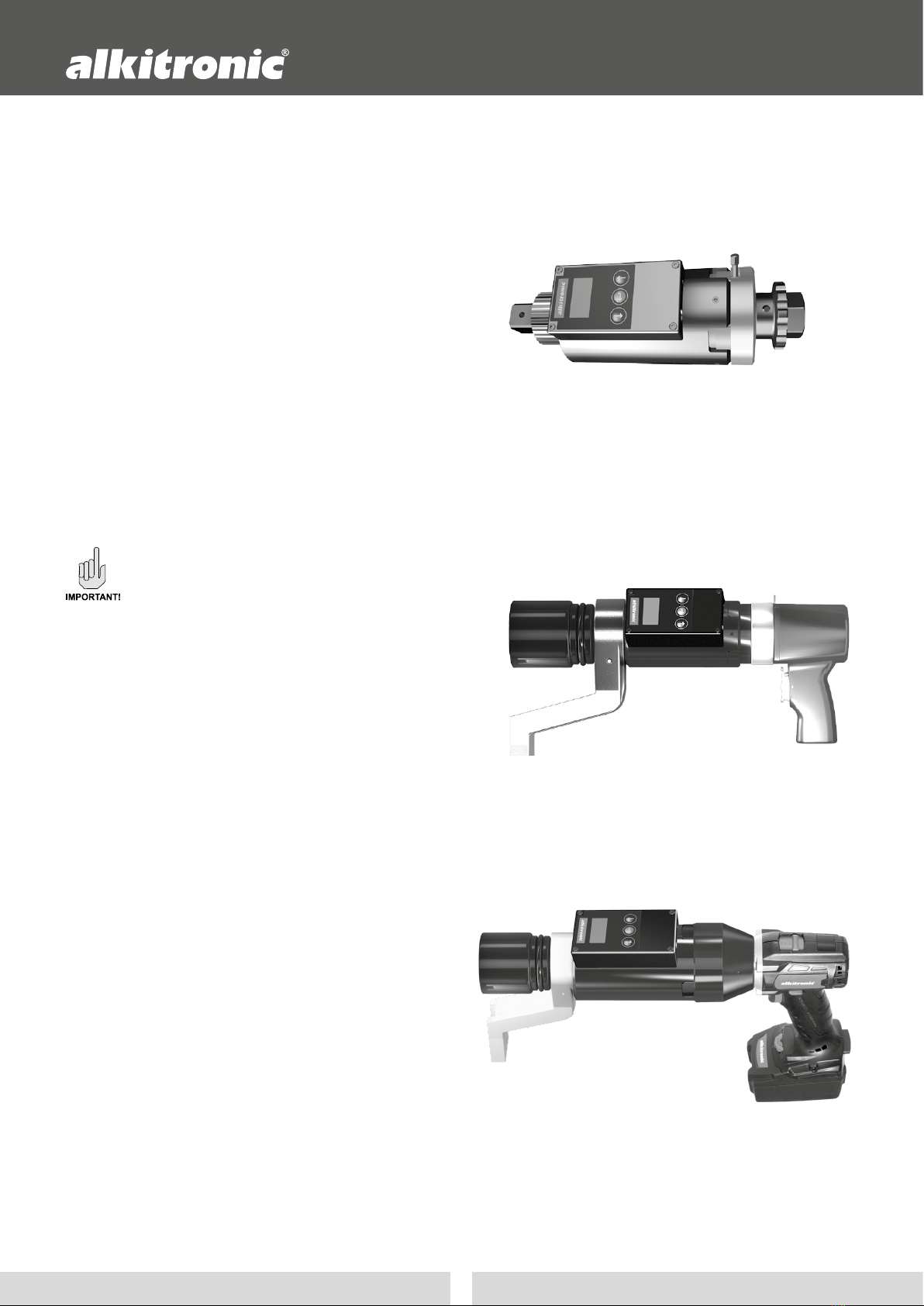
ing: the manually operated alkitronic® HSD, the air
driven
alkitronic® CLSD and the battery-operated alkitronic®
EASD
as well as the battery charger unit included in the delivery
may only be serviced and repaired by employees of alki
TECHNIK GmbH, or specialist trained and qualied by alki
TECHNIK GmbH or sta of a certied and approved third
party company.
Improper maintenance or operation poses a risk of injury
or health hazards and material damages to devices or
machinery; in addition, this will render any warranty or
guarantee null and void.
When using an alkitronic® MDS product the respective
product-specification standard operating and mainte-
nance instructions must be observed.The alkitronic® MDS
operating instructions contain information and instruc-
tions required to be observed for the settings and the
operation of the mounting documentation. Both manuals
must therefore be read by the operators before starting
use of the device. The manuals must at all times be avail-
able for reference at the location where the alkitronic®
tools / devices are used.
These operating instructions refer exclusively to the prod-
ucts of the alkitronic® MDS range.
At all times ensure that the safety instructions listed in the
section “Notices and descriptions” as well as, according
to the situation, all other pertinent general regulations,
notices, recommendations and instructions.
Notices and descriptions
Safety notice to prevent hazards to life and
limb of persons.
Safety notices to prevent damages to alkitronic®
tools, devices, their functions, and the environ-
ment.
Notices to ensure proper and safe operation.
Recommendations to make work easier.
Content Page
A Incoming inspection and packaging 3
B General description 3
B1 Model descriptions 3
1. General technical data 4
2. Safety notices 4
2.1 Proper and correct use 4
2.2 User obligations 4
2.3 Hazard information 5
2.4 Prevention of data loss 5
2.5 Mechanical operation and miscellaneous 5
3. MDS Operation interface sensor electronics 6
3.1 Menu guide / functions (HSD) 6
4. Program preparation / settings 7
4.1 Parameter table alkitronic® MDS torque tools 7
4.2 Starting Sensor electronics 7
4.2.1 Updating / synchronisation of time zones, date
and time settings (alkitronic® APP) 7
4.2.2 Operation Sensor electronics 7
5. Bolting programs (Overview) 7
5.1 Bolting program 1 7
5.2 Bolting program 2 8
5.3 Bolting program 3 9
5.4 Bolting program 4 10
5.5 Bolting program 5 11
6. Technical details 12
7. Function test, storage, maintenance 12
8. Data communication 13
8.1 alkitronic®APP 13
8.2 alkitronic®APP - screens 14
8.2.1 „Device“ screens 15
8.2.2 „Setting“ screens 15
8.2.3 „Info“ screen 15
8.3 CSV Data set 15

3
MDS Mounting Documentation Systems
A Incoming inspection and packaging
Delivery scope alkitronic® HSD
One HSD torque multiplier with reaction support, rachet, bat-
tery charger for the sensor electronics battery, two operation
manual.
Delivery scope alkitronic® CLSD
One CLSD pneumatic torque multiplier with reaction torque
sensor, battery charger for the sensor electronics battery, two
operation manual.
Delivery scope alkitronic® EASD
One EASD rechargeable battery torque multiplier with reac-
tion torque sensor, two high performance rechargeable Li-ion
battery packs with alkitronic® charging station. One charger
for the rechargeable battery of the sensor electronics battery,
two operation manuals.
All parts must be inspected visually upon receipt
of the delivery to check for possible transport dam-
ages. If any such damage is detected, contact the
shipping agent without delay. Retain the original
packaging! Returns must be dispatched in original
packaging to prevent damages to your alkitronic®
tools and devices.
B General description
High quality bolted joints can pose sophisticated challenges
to the bolting tool. The high-performance mounting docu-
mentation system alkitronic® MDS ensures a faultless insertion
and quick and complete recording of bolted joints. alkitronic®
MDS supports in the compliance with legal requirements and
international quality standards (documentation for the end
customer and consumer, retrievable and reliable parameters).
The menu-guided multi-lingual user interface ensures a sim-
ple operation, with control and warning messages as well as
individual fastening and measurement methods available.
Data transfer is by means of a Bluetooth interface for com-
munication with cell phones and other peripheral devices.
For the recording of measurement data and a fast platform-
independent data exchange there is a specially designed
alkitronic® APP (for iOS® and Android® devices).
* all torque values are model-specic
alkitronic® HSD aremanuallyoperatedtorquemultiplierfor:
- torque-controlledtighteningofboltedjointswithtarget
definition and tolerance limits.
- bolted joints independent of data noise in torque / angle
controlled method as well as the documentation on site.
In addition, the torques of bolted joints can be tested. For
development and testing the angles can be determined.
Torque* value range is between 100 Nm and 4,000 Nm.
alkitronic® EASD are rechargeable battery powered torque
multiplier for the torque-controlled tightening of bolted
joints with target denition and tolerance limits with dis-
play and recording of current torque values and documen-
tation on site. Torque* value range is between 100 Nm and
4,000 Nm.
B 1 Model descriptions
alkitronic® CLSD areairdriventorquemultiplierforatorque-
controlled tightening of bolted joints with target denition
and tolerance limits, with display and recording of current
torque values and documentation on site. Torque* value
range is between 100 Nm and 4,000 Nm.

4
Operation and Maintenance Manual
1. General technical data
Ambient temperature range: -20OC bis +50 OC, for further
technical details and notes please see page 12.
Electrical and pneumatic data:
Please refer to the model dependent specications in the
standard operating instructions for the torque multiplier
alkitronic® EA and alkitronic® CL.
2. Safety notices
2.1 Proper and correct use
The electrical power supply to alkitronic® EASD must exclu-
sively be by means of the alkitronic® Li-Ion rechargeable
battery packs. The use of any other battery packs may lead
to an increased risk of fire and injury. The alkitronic® bat-
tery charging base is dimensioned exclusively for charging
alkitronic® Li-Ion battery packs.
The charger supplied with every alkitronic® MDS product is
designed exclusively for use with the rechargeable battery of
the sensor electronics. Any other use is considered improper,
and any damages caused by improper use are not covered
by the manufacturer warranty, but exclusively by the user.
2.2 User obligations
The user or operator must have read and understood the
operating and maintenance instructions before commencing
any work or service activities with the respective device or
tool. Actual bolting may only be carried out by persons who
are fully aware of the purpose, the consequences and exact
process of all actions. Users may not be under the inuence
of substances aecting their consciousness and perception
(e.g., alcohol, drugs, medication).
In case of any queries regarding the safety measures and
instructions or the application either consult your alkitronic®
partner or directly alki Technik GmbH, who will be happy to
assist you.
Incorrect operation, improper use or handling by
unqualied persons may result in severe personal
and/or material damages.
In the workspace the user is responsible to third
parties.
alkitronic® EASD, alkitronic® charging station,
charger for the sensor electronics must not be
used environments with a risk of explosion or
combustion. Before using consult the local health
ands safety regulations and ordinances.
Independent modications or re-engineering of
the products is not permissible.
alkitronic® accessories for torque
multipliers with axial drive
alkitronic® accessories
Original accessories for every
application and joint
alkitronic® STACO
Standard socket
alkitronic® STABI
Standard connector
alkitronic® DMA
Support resp.
torque reaction
counter-poise
alkitronic® EA Li-ION-
rechargeable battery packs

5
MDS Mounting Documentation Systems
2.3 Hazard information
In case of any kind of damage to alkitronic® MDS
torque multipliers or accessories such as Li-ion bat-
tery pack (1), charging station (2) or charger (3) for
the rechargeable batteries of the sensor electronics
stop operation immediately.
The damaged unit must be inspected regarding its
mechanical and electrical safety. Repairs may only
be carried out by authorised and qualied person-
nel; any defects must be remedied or repaired
before the unit is used again.
Before starting repair work on mechanical or
electrical parts all electrical power sources must
be switched o and/or disconnected or the pres-
surized air supply must be disconnected from the
torque tool.
The charging station and/or the charger, as appli-
cable, must also be disconnected from the mains
electricity supply.
3
2
1
Additional safety instructions
Please refer to the standard operating instructions
of the torque tools
alkitronic® M, alkitronic® CL,
alkitronic® EA.
For the following items please see the standard
operating instructions for the torque multiplier
alkitronic® EA.
Operation of the charging station and batteries, operation
battery-powered power screwdriver, preparation / operation
mechanical and electrical, functional and operational test,
maintenance, storage, maintenance / technical specications.
For the following items please see the standard
operating instructions for the torque multiplier
alkitronic® M, alkitronic® CL.
Preparation / operation mechanical and pneumatical, func-
tional and operational test, maintenance, storage, mainte-
nance / technical specications.
Data memory sensor electronics, data commu-
nication
The memory in the MDS devices is limited to accept
data from no more than 400 bolting actions.When
this capacity is exceeded, data is overwritten on a
rst in, rst out basis.
Prevent the loss of stored data by using the
alkitronic® APP with a Bluetooth connection to
read the bolting action data and to transmit the
data to cell phones or other peripherals.
Attention!
This will irretrievably erase the data stored in
memory.
Use the alkitronic®APP to email the data as re-
quired.
Attention!
After sending the email all data will be buered
and stored in a bolt case history. Individual cases
can be emailed again. Once the buer is full, the
oldest data sets are deleted.
For a proper data transfer and archiving only the
operator is responsible. Data loss due to improper
usage by the operator is the sole responsibility of
the operator.
2.4 Prevention of data loss
2.5 Mechanical operation and miscellaneous

6
Operation and Maintenance Manual
3. alkitronic® MDS Operation interface sensor electronics
Operating interface HSD / CLSD / EASD Battery charging socket
Key
Line / Value ( ↑ )
up
Key Start or
Conrm <Enter>
Battery charge status dis-
play
Battery sensor electronics
Text and display eld
Key
( ↓ ) Line / Value
down
Time display update / synchronisation
with alkitronic® APP
OLED Graphic
Display
3.1 Menu guide / functions (HSD)
OLED Graphic Display
General settings Unit
Language
Serial No.
Nm
ft.lb
SW-Version
Back
Program 4
Act. Value
Settings
>
>
>
>
Program 1
Program 2
Program 3
>
Press <Enter> key
Main menu (screen 1) with pro-
gram selection is displayed
> Scroll curser down ( ↓ )
until screen 2 is displayed
> scroll Curser ( ↓ ) down
> Select settings (Adj.)
Press <Enter> key
Screen 3 is displayed
> Scroll curser to required line, e.g.:
> Einheit
press <Enter> key
Screen 3.1 to select Nm or ft.lbe. g.:
> select Nm
press <Enter> key and
return automatically to screen 3
In screen 3 scroll down ( ↓ ) to access
screen 4. Software version can be
displayed or select >Back and press
<Enter> key to return to the main
menu (screen 1)
Screen 1
Screen 2 Screen 4
Screen 3.1
Screen 3
Ladegerät
1
Graphic
2
Graphic
2
Graphic
Examples | Battery charge status
display
Battery 0%
Battery 50%
Battery 100%

7
MDS Mounting Documentation Systems
4. Program preparation / settings
4.2 Starting Sensor electronics
Check charging state of the battery (Graphic 2).
Before starting the battery for the sensor electron-
ics should be fully charged, so that an operating
time of approx. 8 hours is ensured. Charging time
approx. 3 hours.
4.2.1 Updating / synchronisation of time zones, date and
time settings with the alkitronic® APP vornehmen (see also
p. 15, position 6.1.2).
For each program executed the current date in
the format yy/mm/dd/hh/mm is stored and docu-
mented. Other data stored is listed in the program
descriptions.
4.2.2 Operation Sensor electronics
Press key Start or <Enter> (Graphic 1). Select required program
items and follow the menu guide (see pos. 3.1 left side).
When setting parameters please check for plau-
sibility! The value of the desired torque should
therefore correctly be between the minimum and
maximum torque values.
4.1 Parameter table alkitronic® MDS tool
Type Bluetooth Torque
min
Torque max Switching toque
threshold
Name Nm
(10 % v. MDmax.)
Nm Nm
HSD 100 HSD100... 100 1000 50
HSD 200 HSD200... 200 2000 100
HSD 400 HSD400... 400 4000 200
CLSD 100 CLSD100... 100 1000 50
CLSD 200 CLSD200... 200 2000 100
CLSD 400 CLSD400... 400 4000 200
EASD 100 EASD100... 100 1000 50
EASD 200 EASD200... 200 2000 100
EASD 400 EASD400... 400 4000 200
Program overview MDS Tools
1 Torque-controlled bolting HSD
2 Bolting as per torque-controlled or angular process HSD
3 Checking the torque or breakage torque HSD
4 Denition of the required bolting angle HSD
5 Bolting with display of actual torque HSD
1 Torque-controlled bolting CLSD
5 Bolting with display of actual torque CLSD
1 Torque-controlled bolting EASD
5 Bolting with display of actual torque EASD
Target Torque
min. Torque
max. Torque
>Numbers
Start
Back
>
5.1.3 Process description
During the bolting process the torque is increased continu-
ously. As soon as the torque reaches the switching on level
(value see parameter table 4.1) the program will show the
most current maximum torque. If the torque exceeds the pre-
dened minimum torque the user is notied by a visualization
lasting two seconds with a green light and single continuous
signal tone once.
If the currently measured torque increases further and ex-
ceeds the predened maximum torque, the user is notied
by a single continuously uctuating signal tone and the
lighting of a red signal light. Only when the current torque
drops below the maximum predened value or the <Enter>
key is pressed, the warning will be terminated. If the current
drops below the switching level the current bolting data set
is stored in memory.
Display examples Parameter settings
5.1 Bolting program 1
For all MDS product
range products
Make the program
selection in the
main menu.
5.1.1 Application description
Boltings are tightened with a torque target setting and simul-
taneously monitored. The target value for the torque can be
entered within a tolerance range. The target torque value is
pre-dened; and always the currently applied torque value
is stored in memory.
5.1.2 Parameter setting
• Target torque
• Minimum torque
• Maximum torque
• Number of bolted joints
The parameters on the left-
must all be entered to ensure
correct data recording and
evaluation.
5. Bolting programs

8
Operation and Maintenance Manual
The system will start after a waiting time of ve seconds. If
during this waiting time the <Enter> key is pressed, the system
is immediately ready for the next bolting process.
When further bolting process are carried out the counter will
be increased. The number of completed and the grand total
number of bolting processes are shown in the display.
If, however, the maximum number of bolting processes has
been reached, the program will terminate and the system will
return to the main menu.
Note:
If during a screwing process the
<Enter> key is pressed, a query
will be displayed: End program?
No – Yes. Select the correct
answer with the cursor key ( ↓ ) ( ↑ ) and conrm by pressing
the <Enter> key.
End?
No
Yes
>
Status Status
> max. torque Not OK
< min. torque Not OK
Between max. and min. torque OK
Value Content
Year/Month/Day/hours/minutes
ID Global counter ID (incremented by each process)
Program 1
Current torque Maximum value during the measurement
Target torque As predened
Min. Torque As predened
Max.Torque As predened
Status OK / not OK
5.1.4 Assessment criteria
Depending on the assessments as follow the result is stored:
5.1.5 Documentation
5.2 Bolting program 2
Exclusively for the
HSD model of
MDS product range.
Make the program
selection in the
main menu.
5.2.1 Application description
Bolted joints are tightened with a torque and rotation angle
setting. The target torque value can be entered with tolerance
limits. The actual torque applied and the angle achieved is
stored in memory.
5.2.2 Parameter setting
• Number of boltings
• Min. torque
• Max. torque
• Pre-set torque
• Target angle
When setting the parameters plausibility must be
maintained. Note that the pre-torque is smaller
than the minimum torque, and this must be lower
than the maximum. All torque values must be limi-
ted between the minimum and maximum torque
value of the torque multiplier (see parameter table
4.1).
5.2.3 Process description
During the screwing process the torque is increased con-
tinuously. As soon as the torque reaches the switching on
level (value see parameter table 4.1) the program will show
the most current maximum torque. If the torque exceeds the
predened pre-torque the angle measurement commences.
As soon as the angle is greater than the predened target
angle (minus 5% tolerance) and the currently torque is greater
than the minimum torque the user is notied by a visualization
lasting two seconds with a green light and single continuous
signal tone once.
If the currently measured torque increases further and ex-
ceeds the predened maximum torque, the user is notied
by a single continuously uctuating signal tone and the
lighting of a red signal light. Only when the current torque
drops below the maximum redened value or the <Enter>
key is pressed, the warning will be terminated. If the current
drops below the switching level the current screwing data
set is stored in memory.
OK
350 Nm
Display: The currently measu-
red max. torque and the evalu-
ation of the screwing process is
shown as “OK” or “nOK”.
The parameters on the left-
must all be entered to ensure
correct data recording and
evaluation.

9
MDS Mounting Documentation Systems
The system will start with a waiting time of ve seconds; if
further bolt jobs are pending, the counter is incremented up
(the number of completed and the total number of bolted
joints are displayed on the screen). The next bolting action
can be started.
Set the torque tool to the next bolting point. Before
each subsequent bolting action the <Enter> must
be pressed.
If, however, the predened maximum number of bolting
actions has been reached, the program will terminate and
switch to the main menu.
Between max.
torque and
min. torque
angle < target minus 5° Not OK
angle > target plus 5° Not OK
angle between target minus 5°
and target plus 5°
OK
Status Status
> max. torque Not OK
< min. torque Not OK
Note:
If during a bolting action the
<Enter> key is pressed there will
be a query screen: End program?
Select with the >cursor ( ↓ ) ( ↑ )
and conrm with the <Enter> key.
End?
No
Yes
>
Wert Content
Year/Month/Day/hours/minutes
ID Global counter ID (incremented by each process)
Program 2
Current torque Maximum value during the measurement
Minimum torque As predened
Maximum torque As predened
Pre-torque As predened
Target angle As predened
Current angle Maximum value during the measurement
5.2.4 Assessment criteria
Depending on the assessments as follow the result is stored:
5.2.5 Documentation data
5.3 Bolting program 3
Exclusively for the
HSD model of
MDS product range.
Make the program
selection in the
main menu.
5.3.1 Application description
Program for checking previously tightened torque values.
Bolted joints are tightened with a predened angle; the target
torque must be pre-dened within the tolerance limits.The ac-
tually applied torque is tested and simultaneously evaluated.
Determination of the breaking torque (counter-clockwise).
5.3.2 Parameter setting
• Number of boltings
• Target angle
• Min. torque
• Max. torque
OK
2150 Nm
29 RO
Display: The current torque mea-
sured and the max. angle is dis-
played. The evaluation of the
screwing process is shown as
“OK” or “nOK”.
5.3.3 Process description
During the tightening process the torque increases conti-
nuously. When the torque reaches the switching threshold
(value see parameter table 4.1) the program continues to show
the current max. torque and will also simultaneously measure
the rotation angle. When the current rotation angle exceeds
the predened target angle (minus 1° tolerance) the user is
notied by a visual signal from a green LED for two seconds
and a long signal tone. If the measured torque continues to
increase and exceeds the predened maximum the user is
notied by a continuously interrupted signal tone and a red
light.This warning will switch o when the torque falls below
the maximum or the <Enter> key is pressed.
Once the current torque drops below the switching threshold
the bolting data is stored in memory and evaluated.
The parameters on the left-
must all be entered to ensure
correct data recording and
evaluation..

10
Operation and Maintenance Manual
The system will start with a pause of ve seconds. If more
bolting processes are due, the counter will increment and the
total number of completed bolting processes and the grand
total are displayed on the screen.
If the <Enter> key is pressed during the pause the system will
be ready for the next bolting process immediately.
Once the predened number of bolting process has been
reached the program will terminate and the main menu
appears on the display.
Note:
If during a screwing process the
<Enter> key is pressed, there will
be a conrmation query prompt
on the screen: End program?
Make the selection with the > cursor ( ↓ ) ( ↑ ) and conrm
with the <Enter> key.
End?
No
Yes
>
Status Result
> (minus 1°) or equal target angle OK
< or > target angle Not OK
> max. torque Not OK
< min. torque Not OK
< max. torque and > min. torque OK
5.3.4 Assessment criteria
Depending on the assessment described below the result is
stored in memory:
Value Content
Year/Month/Day/hours/minutes
ID Global counter ID (incremented by each process)
Program 3
Current torque Maximum during measurement
Target angle As dened
Current angle Maximum during measurement
Min. torque As dened
Max. torque As dened
Status OK/ Not OK
5.3.5 Documentation data
5.4 Bolting program 4
Exclusively for the
HSD model of
MDS product range.
Make the program
selection in the
main menu.
5.4.1 Application description
This program determines the required rotation angle, for
example for the use in testing and development projects.
Pre-torque and target and nal torque are predened. Mea-
surement and storage of achieved rotation angle.
5.4.2 Parameter setting
• Number of rotation
angle determinations
• Target torque
• Pre-torque
When setting the parameters always check for
plausibility: The pre-torque must be smaller than
the target torque. All torque predenitions must
be between the minimum and maximum torque
values of the torque multiplier (see parameter table
4.1).
2 / 10
2050 Nm
18 RO
Screen display: the current
measured max. torque, the
number of completed screwing
processes, as well as the grand
total.
OK
1850 Nm
8 RO
Screen display: The currently
measured max. torque, the max
rotation angle with direction.
The parameters on the left-
must all be entered to ensure
correct data recording and
evaluation.
5.4.3 Process description
During the tightening process the torque increases conti-
nuously. When the torque reaches the switching threshold
(value see parameter table 4.1) the program will continue to
display the latest max. torque and the rotation angle.
If the measured torque exceeds the predened pre-torque
the rotation angle measurement will be started.
If the measured torque exceeds the target torque the rotation
angle measurement is terminated. If the measured torque
drops below the switching threshold the process is saved to
memory.

11
MDS Mounting Documentation Systems
Value Content
Year/Month/Day/hours/minutes
ID Global counter ID (incremented by each process)
Program 4
Pre-torque As dened
Torque As dened
Current angle Maximum during measurement
Value Content
Year/Month/Day/hours/minutes
ID Global counter ID (incremented by each process)
Program 5
Current torque Maximum during measurement
5.4.4 Documentation data
5.5.4 Documentation data
The system will start with a pause of ve seconds. If more angle
measurement processes are due, the counter will increment
and the total number of completed bolting processes and
the grand total are displayed on the screen; further angle
measurements can be carried out.
If the <Enter> key is pressed during the pause the system will
be ready for the next bolting process immediately.
If, however, the predened number of bolting process has
been reached the program will terminate and the main menu
appears on the display.
5.5 Bolting program 5
Exclusively for the models
CLSD and EASD
of the MDS product range.
Make the program
selection in the
main menu.
5.5.1 Application description
All boltings are carried out without any torque pre-settings.
This program measures and stored only the torque peak of
a bolting process.
5.5.2 Parameter setting
• Number of boltings
5.5.3 Process description
During the tightening process the torque increases conti-
nuously. When the torque reaches the switching threshold
(value see parameter table 4.1) the program will continue
to display the latest max. torque. If the measured torque
drops below the switching threshold the process is saved to
memory.
2 / 10
2350 Nm
Screen display: The current
measured max. torque, the
number of processed bolting
processes and the grand total.
Note:
If during a screwing process the
<Enter> key is pressed, there will
be a conrmation query prompt
on the screen: End program?
Make the selection with the > cursor ( ↓ ) ( ↑ ) and conrm
with the <Enter> key.
End?
No
Yes
>
The system will start with a pause of ve seconds. If more angle
measurement processes are due, the counter will increment
and the total number of completed bolting processes and
the grand total are displayed on the screen; further angle
measurements can be carried out.
If the <Enter> key is pressed during the pause the system will
be ready for the next bolting process immediately.
If, however, the predened number of bolting process has
been reached the program will terminate and the main menu
appears on the display.
Recommendation for all bolting programs:
Always complete the predened total number
of bolting processes. If individual processes are
rated as not OK, these should be highlighted
and repeated in a new bolting process. The
re-set parameters will remain in force, only the
number of the processes must be adjusted.
The parameter on the left
must be entered to ensure
correct data recording and
evaluation.

12
Operation and Maintenance Manual
alkitronic® HSD alkitronic® EASDalkitronic® CLSD
Models HSD / CLSD / EASD
Type HSD 100 HSD 200 HSD 400 CLSD 100 CLSD 200 CLSD 400 EASD 100 EASD 200 EASD 400
Measurement range approx. Nm 100-1000 200-2000 400-4000 100-1000 200-2000 400-4000 100-1000 200-2000 400-4000
Power (max) Nm 1000 2000 4000 1000 2000 4000 1000 2000 4000
Square drive B 1” 1” 1 1/2“ 1” 1” 1 1/2“ 1” 1” 1 1/2“
Diameter (approx.) D1mm 54 54 72 54 54 72 54 54 72
Diameter (approx.) D2mm 88 88 98 88 88 98 88 88 98
Length (approx.) L mm 220 295 320 360 390 410 370 405 425
Weight without DMA (approx.) kg 6,4 7,6 11,35 10 11,25 15 8,7 10 13,5
Idle speed, 1st gear U/min - - - 11 5 3,5 5 2 1
6. Technical details
alkitronic® MDS Sensor electronics
When fully charged, the battery has a capacity for approx.
eight hours of operation. The internal buer storage has a
capacity to save data of 400 bolting processes.
alkitronic® MDS charger
220-240 V / 50-60 Hz
Output 5 V / 2,0 A max.
Full charge over 3 hours.
alkitronic® EASD + Accessories
alkitronic® Li-Ion rechargeable battery pack
Voltage 18 V, 5,2 Ah. Charging time approx. 100 min.
Optimum storage temperature 100 - 300.
alkitronic® charging station
220-240 V / 50-60 Hz / 65 W
Output 12-42 V / 3,0 A max.
(optional 110 V / 50 Hz)
alkitronic® CLSD
An air pressure of 3-7 bar at a volume air ow of approx.
10-15 l/sec ensures best working quality. The torque pre-set-
ting is either carried out on the maintenance unit (accessory)
or on the air supply according to the attached graph chart.
7. Function test, storage, maintenance
Always follow, apart from the instructions bellow the standard
operating instructions for the power torque tools alkitronic® M,
alkitronic® EA and alkitronic® CL. Torque multiplier, air hoses
and accessories must regularly be inspected for damages and
immediately replaced properly in case any damages are found.
When taking torque tools out of service, store the cleaned and
dry units in their tool-case or a lockable container. Heat and
humidity will cause oxidation on the gears, resulting in malfunc-
tions.
The alkitronic® MDS torque tools are extremely robust and high
performance products. To ensure a long mean time before fail-
ure and reliability over many years regular maintenance work is
required (performance check, safety tests, calibration service).
As part of the regular maintenance the recharge-
able battery must be replaced every ve years.
In case of necessary maintenance or repair work send the
alkitronic® MDS products in their original packaging to your
nearest alkitronic® Partner or directly to alki Technik GmbH.
Your alkitronic® Partner would be please to answer any ques-
tions you may have.

13
MDS Mounting Documentation Systems
8. Data communication
alkitronic®APP was developed for the measurement data
recording and quick exchange with iOS® and Android®
cell phones or tablets. File transmission is via platform
independent data exchange of CSV files via email.
The alkitronic®APP is available for download in the Apple®
App-Store or for Android® e.g. in the Google® Play Store.
8.1 alkitronic®APP
alkitronic®APP application scheme
Sensor torque
tool e.g.:
alkitronic®HSD
Bolting
object
CSV -
Files
Bluetooth
Android® Version
(Google® Play Store)
Find torque tools: On the
MDS torque multiplier the
sensor electronics must be
switched on (see also p. 6,
pos. 3, graphic 1).
Icon
alkitronic®APP
Example:
Status after installation
(Android®)
View iPhone/iPad
When a working Bluetooth con-
nection has been established,
a “BT” is displayed on the MDS
torque tool screen.
View Android Phone/Pad
In order to connect the alkitronic® MDS torque tool/s
the Bluetooth interface on the phone or pad must be
activated.
Status after starting the alkitronic® APP :
Program 1
Program 2
Program 3
>
BT
Devices
Devices
Settings
Settings
Info
Info
search for devices
installation

14
Operation and Maintenance Manual
8.2 alkitronic®APP - the screens
8.2.1 »Device« Screens
Devices
The screen “Devices” displays, as an
example, the linked MDS torque
multiplier HSD100. Other devices are
stored behind the button “Available
devices” and can be activated at
any time. After pressing the button
“connected device”(HSD100…) three
Screen Device management
E.g. display of specic device / torque
tool data.
Settings Info
Reading of the latest
bolting project data.
Reading of current bolting project data
Emailing of bolting
project data.
Bolting process detail
information
Optional display of ALL
bolting processes or
only of the nOK ones.
further functions are made available.
Torque multipliers currently not
required can be faded out; torque
multipliers can be removed and the
device data displayed through the
device management.
After touching “Fade out” the torque
tool will be available under “faded
out devices”.
Navigation principles:
The navigation has been realized with
an accordion function. Press (
v
) to
display contents, and press
to hide contents.
(
v
)
xxxx.xxxxxx
>
>
>

15
MDS Mounting Documentation Systems
8.2.3 »Info« Screen
8.3 CSV Data set (Example Program 1 with 6 bolting processes, pre-sets Target/Min./Max. Torque in Nm)
8.2.2 »Settings« Screens
Settings
Information
Your fastest way to alkitronic®.Conrmation before sending.
Resend of bolting process data from
the email history list .
Recall of sent bolting process data
(email history list).
Synchronisation with
MDS tools (ON/O)
E-Mail
personalisation
Language selection
Debug function for diagnostics and
trouble shooting.
ExportTime: Tue, 31 May 2016 13:41:38 GMT | id: D32E6A14-
EB7D-D2C5-7D22-979A0F3EB41E | name: EA_000001 |
bezeichnung: EA_000001 | isVisible: true | isConnected: true |
rstConnectTime:2016-05-31T12:02:14.362Z | lastConnectTime:
2016-05-31T13:40:35.441Z | schrauberInfo: [object Object] |
ID program time status current torque target torque min. torque max. torque
0 1 2016-05-31T13:21:38.016Z 1320 301 201 403
1 1 2016-05-31T13:22:38.016Z 0420 301 201 403
2 1 2016-05-31T13:22:38.016Z 1295 301 201 403
3 1 2016-05-31T13:24:38.016Z 1305 280 250 350
4 1 2016-05-31T13:25:38.016Z 1285 280 250 350
5 1 2016-05-31T13:25:38.016Z 1295 280 250 350
Status 0 means a faulty screwing pro-
cess, the current torque is too high.
©alkitechnik / GBA MDS/2/29-04-19/4Pdesign/
Technical Details are subject to be changed without prior notice

alki TECHNIK GmbH
Development, Production and Distribution of Bolting Systems
Unterlettenweg 4 – 85051 Ingolstadt/Germany – fon +49 841 97499-0 – fax +49 841 97499-90
info@alkitronic.com – www.alkitronic.com
Increased quality
Premium production
Highest quality materials
Long product life cycles
30 years experience in bolting technology
Made in Germany – international patents
Increased productivity
Quicker tightening without reworking
No environmentally caused failures (IP54, ATEX)
High work safety
Easy to use: clear, simple instructions
Low maintenance and cost ecient
Increased precision
Precise, customer-specic torques
High repeatability
Reliability in permanent operation
Dokumentation of tightening results
Automatic shut-off
Better service
Technical advice on site
Training offers
Manufacturer’s calibration and certication
Lifecycle support
Spare part and repair service
YOUR PLUS FOR MORE PERFORMANCE
Hydraulic Wrenches and Pumps Manual Torque Multiplier
Electric Torque Multiplier Pneumatic Torque Multiplier
EXTRACT FROM OUR PRODUCT RANGE
This manual suits for next models
9
Table of contents
Popular Test Equipment manuals by other brands

Clinton
Clinton DC-1 instruction manual

Nitty-Gritty
Nitty-Gritty PASSI TEST PLUS owner's manual

Rigol
Rigol DS1074B Service guide

DeFelsko
DeFelsko PosiTest DT instruction manual

Aventics
Aventics Essential-Test-Box operating manual

Agilent Technologies
Agilent Technologies InfiniiVision MSO6104A Service note