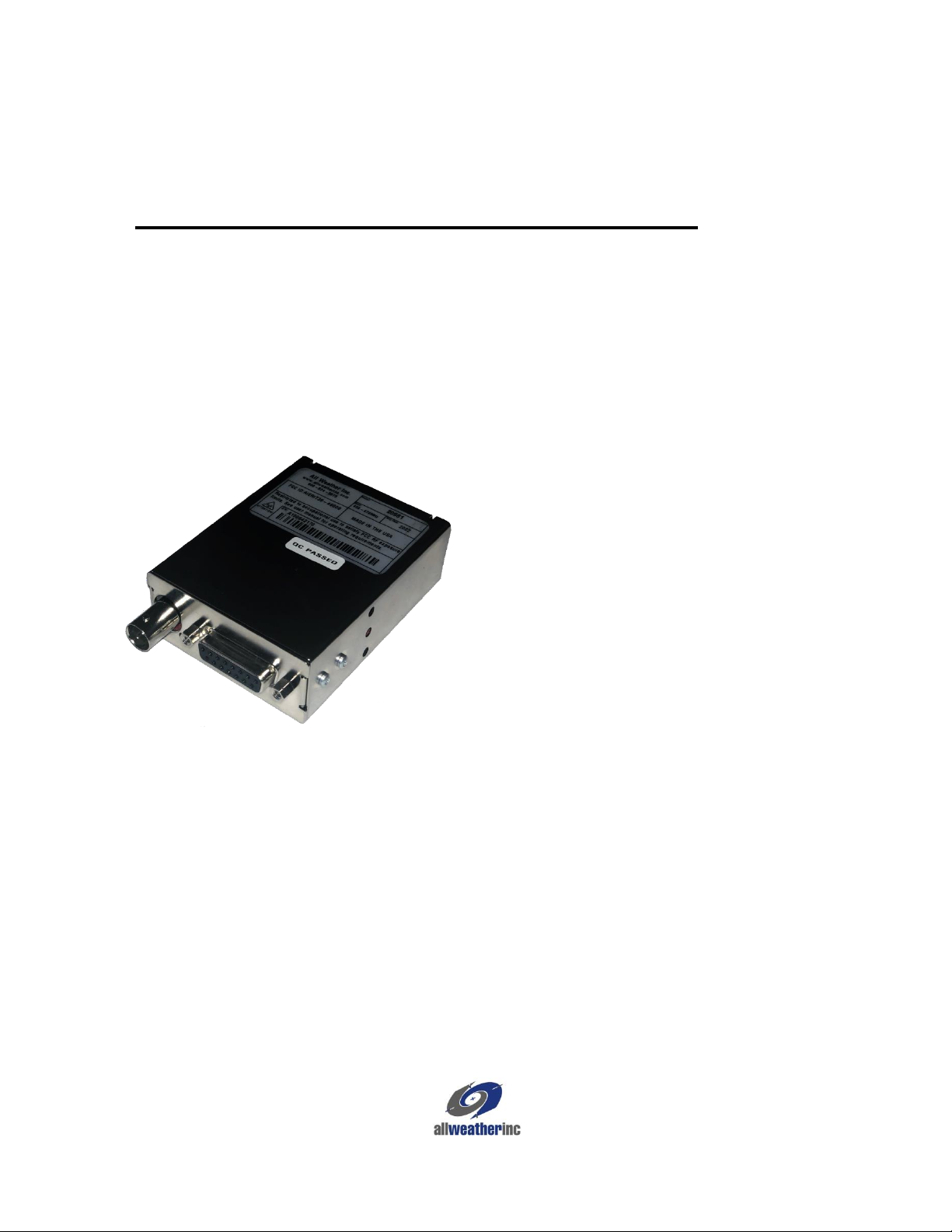
Model 20981 UHF Data Radio User’s Manual
TABLE OF CONTENTS
OVERVIEW.........................................................................................................................1
1.1 Installation Kits...........................................................................................................................1
1.2 FCC Regulations.........................................................................................................................1
1.2.1 Licensing.............................................................................................................................1
1.2.2 Equipment Authorization (Certification)............................................................................1
1.2.3 Radio Frequency Exposure.................................................................................................2
I/O CONNECTOR AND LED INDICATORS........................................................................3
2.1 I/O Connector .............................................................................................................................3
2.1.1 Pinout Description ..............................................................................................................3
2.2 LED indicators............................................................................................................................5
OPERATION.......................................................................................................................6
3.1 Channel Selection.......................................................................................................................6
3.2 Power Supply Voltage................................................................................................................6
3.3 Current Drain vs Supply Voltage ...............................................................................................6
3.4 Duty Cycle/Key-Down Limitations............................................................................................7
INSTALLATION...................................................................................................................8
PROGRAMMING THE DATA RADIO .................................................................................9
5.1 Frequency Tab..........................................................................................................................10
5.2 Other Tabs ................................................................................................................................10
5.2.1 Buttons..............................................................................................................................10
5.2.2 General Tab.......................................................................................................................11
5.2.3 Modem Page .....................................................................................................................12
5.3 Analog Tab ...............................................................................................................................14
5.4 Summary Tab............................................................................................................................15
5.5 Restore EE Tab.........................................................................................................................15
AWOS INSTALLATION.....................................................................................................17
6.1 DCP Installation........................................................................................................................17
6.2 CDP Installation........................................................................................................................17
MAINTENANCE................................................................................................................18
7.1 AWOS Maintenance Procedures..............................................................................................18
7.1.1 Monthly Maintenance.......................................................................................................18
7.1.2 Triannual Maintenance .....................................................................................................19
7.1.3 Annual Maintenance.........................................................................................................19
SPECIFICATIONS ............................................................................................................21
WARRANTY......................................................................................................................23