All Weather Inc 1793 User manual

All Weather Inc. • 1165 National Drive • Sacramento, CA 95834 • USA • 800.824.5873 • www.allweatherinc.com
User’s
Manual
Rev. A
Model1793
VHFRadio
FAA APPROVED
ECP232 —2017 Jul 28
NOT FAA APPROVED

Copyright ©2016, All Weather, Inc.
All Rights Reserved. The information contained herein is proprietary and is provided solely for the purpose of
allowing customers to operate and/or service All Weather, Inc. manufactured equipment and is not to be released,
reproduced, or used for any other purpose without written permission of All Weather, Inc.
Throughout this manual, trademarked names might be used. Rather than put a trademark (™) symbol in every
occurrence of a trademarked name, we state herein that we are using the names only in an editorial fashion and to
the benefit of the trademark owner, and with no intention of infringement. All Weather, Inc. and the All Weather,
Inc. logo are trademarks of All Weather, Inc.
Disclaimer
The information and specifications described in this manual are subject to change without notice.
Latest Manual Version
For the latest version of this manual, see the User Manuals page on our web site at
http://www.allweatherinc.com/support/support-library/user-manuals/.
All Weather, Inc.
1165 National Drive
Sacramento, CA 95834
Tel.: (916) 928-1000
Fax: (916) 928-1165
Contact Customer Service
Phone support is available from 8:00am - 4:30pm PT, Monday through Friday. Call 916-928-1000
and ask for “Service.”
Online support is available by filling out a request at www.allweatherinc.com/support/online-support/
E-mail your support request to support@allweatherinc.com

1793 VHF Radio User's Manual
TABLE OF CONTENTS
1. INTRODUCTION.................................................................................................................1
1.1 Description..................................................................................................................................1
2. INSTALLATION AND CHECKOUT.....................................................................................1
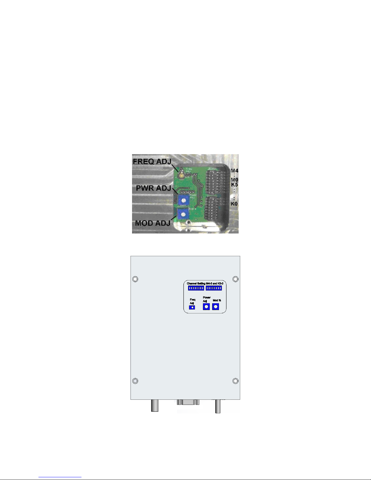
2.1 Setting the Transmitter Frequency..............................................................................................1
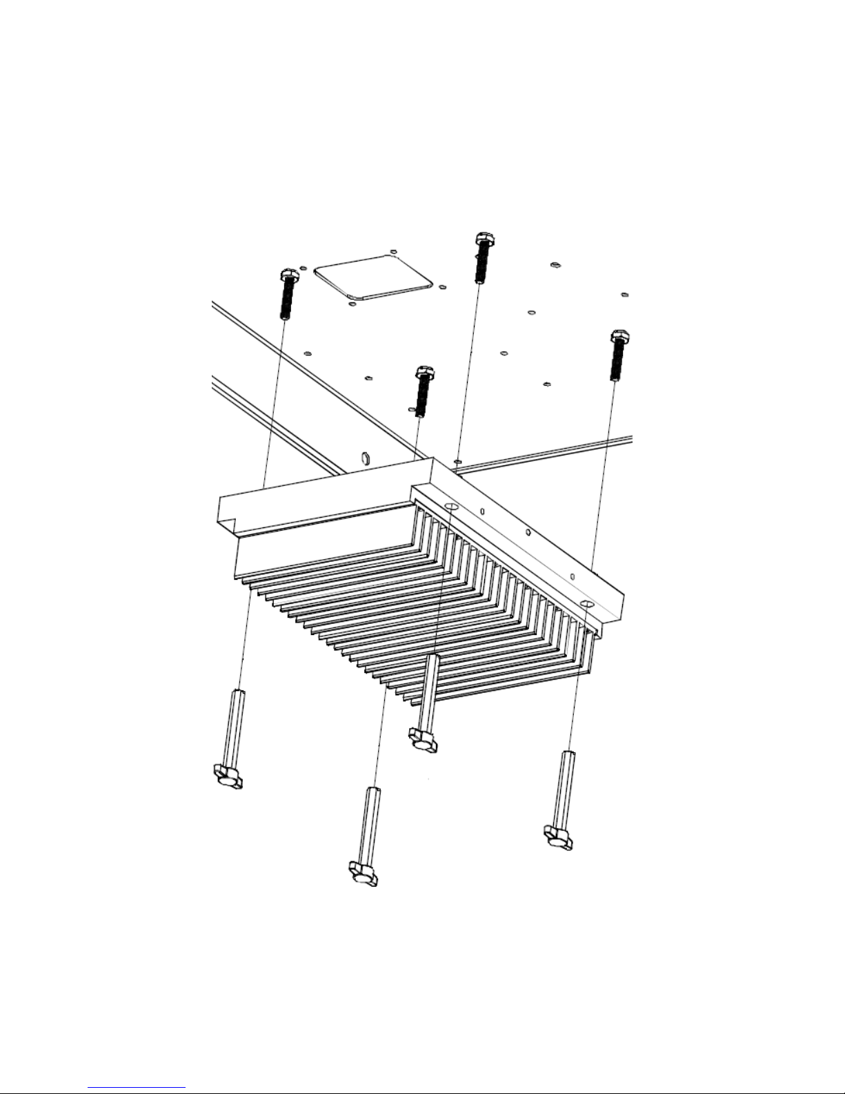
2.2 Mounting Bracket.......................................................................................................................3
2.3 Connections ................................................................................................................................5
2.4 Calibration ..................................................................................................................................7
2.5 Operational Check......................................................................................................................7
3. OPERATION.......................................................................................................................8
3.1 Operating VHF Radio Instructions.............................................................................................8
3.2 Switching VHF Radio OFF........................................................................................................8
4. MAINTENANCE................................................................................................................11
4.1 Periodic Maintenance ...............................................................................................................11
4.1.1 Monthly Maintenance.......................................................................................................11
4.1.2 Triannual Maintenance .....................................................................................................11
4.1.3 Annual Revalidation .........................................................................................................11
5. SPECIFICATIONS ............................................................................................................20
6. FORMS.............................................................................................................................21
7. WARRANTY......................................................................................................................23

1793 VHF Radio User's Manual
1
1. INTRODUCTION
This publication provides general information on the Model 1793 VHF Radio. The Model 1793
VHF Radio is a single channel, fixed frequency Amplitude Modulated (AM) transmitter
operating over the frequency range of 118.000 to 136.975 MHz. The transmitter is intended for
base station operation in an air traffic environment. The Model 1793 operates on DC voltage in
the range of 11.25 to 16.25 volts.
1.1 DESCRIPTION
Each Model 1793 VHF Radio consists of a transmitter board mounted in a heat sink as shown in
Figure 1. The transmitter is a low power VHF AM transmitter which can transmit on a single
programmable synthesized frequency, with 25 kHz channel spacing in the frequency range of
118.000 to 136.975 MHz. The channel selection switches are accessible below the heatsink. The
transmitter requires a DC Power input that supplies voltage to the transmitter and linear
amplifier.
Figure 1. VHF/AM Single Channel Transmitter

1793 VHF Radio User's Manual
1
2. INSTALLATION AND CHECKOUT
Before using the VHF Radio, it is necessary to set the operating frequency.
2.1 SETTING THE TRANSMITTER FREQUENCY
The operating frequency may be programmed over the frequency range of 118.000 to 136.975
MHz with 25 kHz channel spacing. To access the frequency jumper settings access the bottom of
the radio, opposite side of the heat sink see Figure 3. The operating frequency is selected by
setting the eleven switches on DS401 and DS402 shown in Error! Reference source not found.
and Figure 3. Refer to Figure 4 for the frequency selection switch settings. Fine-tuning the
frequency is achieved by adjusting C427.
Figure 2. Adjustments and Frequency Setting Jumpers
Figure 3. Model 1793 Bottom View

1793 VHF Radio User's Manual
2
Figure 4. Frequency Selection Switch Map

1793 VHF Radio User's Manual
3
2.2 MOUNTING BRACKET
The CDP rack’s bottom shelf (Figure 5) is fixed in place. Components are accessible through the
rack’s front or side doors. The VHF radio is secured to the bottom side of the sliding top shelf
using four wing knobs facing up when the VHF radio is viewed from the front end of the CDP
rack.
Figure 5. CDP Bottom-Shelf Components

1793 VHF Radio User's Manual
4
The mounting bracket and the VHF radio are installed at the factory. Should the need arise to
remove the radio, undo the four wing knobs on either side of the radio. Because of the tight space
inside the CDP rack, it is recommended that any connecting cables remain in place until the VHF
radio is removed from the siding shelf. Any cables that have been removed should be reattached
before mounting the VHF radio back in the mounting bracket. Figure 6 shows how the VHF
radio is secured to the siding shelf.
Figure 6. VHF Radio Secured in Mounting Bracket Using Four Wing Knobs

1793 VHF Radio User's Manual
5
2.3 CONNECTIONS
In the All Weather, Inc. AWOS 3000 system, the 1793 VHF radio is installed at the Central Data
Platform (CDP). The VHF control cable connects the VHF radio to the AWOS Peripheral
Interface PCB at terminal block J2 and the AWOS computer power supply. The cable is fitted
with a DB9 connector at one end for connection to the VHF radio. It has four unterminated wires
at the other end for connection to the Peripheral Interface. The cable also has a four pin Molex
power connector to supply power to the VHF radio from the AWOS computer power. The
antenna connector is a 50 ohm "BNC" Type connector. For runs longer than 50 feet, RG-8 cable
should be used.
To connect a 1793 VHF radio to an AWOS 3000 perform the following steps:
1. Ensure that the radio POWER ON/OFF switch is set to OFF.
2. Connect the antenna cable to the front panel BNC connector.
3. Connect the signal / power cable DB9 connector to the 9-pin D connector on the radio
front panel.
4. Connect the unterminated end of the signal cable to terminal block J2 on the Peripheral
Interface board as follows:
a. Signal cable WHITE wire to pin 1.
b. Signal cable GREEN wire to pin 2.
c. Signal cable RED wire to pin 3.
d. Signal cable BLACK wire to pin 4.
5. Connect the 4 pin connector to the AWOS computer power supply.
6. Power on the radio by switching the radio POWER ON/OFF switch to the ON position.

1793 VHF Radio User's Manual
6
Figure 7. VHF Radio Connections
Figure 8. Connector Pinout

1793 VHF Radio User's Manual
7
2.4 CALIBRATION
The Model 1793 VHF Radio is calibrated at the factory prior to shipment, and should not need to
be calibrated again during installation. Power level and modulation calibration are performed as
part of the annual revalidation described in the Annual Revalidation Section.
2.5 OPERATIONAL CHECK
Ensure that the transmitter operates as described in Chapter 3.

1793 VHF Radio User's Manual
8
3. OPERATION
A view of the front and transmitter indicators is given in Figure 9. A functional description of the
power switch, controls, and indicators is provided in Table 1.
3.1 OPERATING VHF RADIO INSTRUCTIONS
1. Ensure that the power, signal, and antenna cables are connected.
2. Set the POWER ON/OFF switch to "ON".
3. Verify that the amber POWER ON LED is ON as shown in Figure 9.
4. Verify that the AWOS station voice message is being transmitted using a VHF receiver.
5. Ensure that the Tx ON amber LED cycles ON during voice message output.
6. Verify that the Tx ON amber LED cycles OFF between voice message broadcasts.
3.2 SWITCHING VHF RADIO OFF
1. Set the POWER ON/OFF on transmitter to switch to OFF.
2. Verify that all indicator LED's on the bottom heatsink side are OFF.

1793 VHF Radio User's Manual
9
Figure 9. Transmitter Controls and Indicators

1793 VHF Radio User's Manual
10
Table 1. Operator's Switches, Controls and Indicators
SWITCHES
CONTROLS &
INDICATORS
FUNCTIONAL DESCRIPTION
ON/OFF
SWITCH
The toggle switch applies the DC power to the transmitter. The transmitter is
switched to ON in the toggle LEFT position the transmitter is switched OFF in the
toggle RIGHT position.
PWR LED
INDICATOR
The PWR AMBER LED Indicates when the POWER ON/OFF switch is set to ON
and voltage is applied to the transmitter.
PTT
AMBER LED
INDICATOR
The PTT AMBER LED indicates when the transmitter is in the transmit mode.
The PTT AMBER LED switches OFF, when the transmitter is in the stand-by
mode.
MOD
BLUE LED
INDICATOR
The Blue LED indicates when the transmitter is receiving audio modulation.
DB 9 PIN
CONNECTOR
The 9 pin "D" connector connects the power, audio signal, and TX transmit
signal.
RF OUT
A 50 ohm BNC coaxial connector provides a connection to the external antenna.

1793 VHF Radio User's Manual
11
4. MAINTENANCE
The Model 1793 VHF Radio requires no maintenance, other than the recommended periodic
checks outlined below. If transmission problems should arise, perform the Annual Revalidation
procedures described in below. If the problem persists, contact All Weather, Inc. Customer
Service.
4.1 PERIODIC MAINTENANCE
Periodic maintenance of the Model 1793 VHF Radio is divided into three categories within the
maintenance cycle: monthly, triannual, and annual maintenance procedures.
4.1.1 Monthly Maintenance
Check the cabling for integrity. Verify the voice output. Verify the PTT LED indicator
illuminates when voice output is activated.
4.1.2 Triannual Maintenance
Triannual maintenance of the VHF radio is identical to that specified in the monthly maintenance
procedure.
4.1.3 Annual Revalidation
Annual Revalidation involves measures the Output Power, VSWR, Frequency, and Modulation
of the VHF radio.
Equipment Required
The test equipment listed in Table 2 is required to perform an annual revalidation.
Table 2. Equipment Required
Radio Test Equipment
Power Meter
Bird Watt Meter Model 43 or equivalent
Dummy Load
50 Ohms, 10 Watts, @ 140 MHz
Various Cables
Coaxial Jumper cables, RF adapters, etc.
Forward/Reflected Power
Tester
Bird Watt Meter Model 43 w/ 10C elements or equivalent
Frequency Meter
Aeroflex 3500 or equivalent
Modulation Meter
Aeroflex 3500 or equivalent
Deviation Meter
Aeroflex 3500 or equivalent
When the VHF antenna cable is longer than 50 feet, the VSWR and Power Level tests must be
repeated at the antenna end of the cable.

1793 VHF Radio User's Manual
12
4.1.3.1 Power Level (At Transmitter)
1. Remove power from the VHF radio by turning the power switch on the radio front panel
off.
2. Disconnect the VHF antenna cable from the BNC connector on the back panel of the
CDP.
3. Connect the power meter to the BNC connector on the back panel of the CDP which
connects to the VHF radio internal to the AWOS 3000.
4. Connect the antenna or a 50 ohm 10 watt dummy load to the other connector on the
power meter to terminate the VHF radio output. See Figure 10 for a functional
connection description.
Figure 10. Insert Power Meter Between Antenna and VHF radio
5. Apply power to the VHF radio by turning the power switch on the radio front panel on.
6. Record the VHF radio output power level on the Annual Technical Performance Record.
7. Remove power from the VHF radio by turning the power switch on the radio front panel
off.
8. Disconnect the power meter from the BNC connector on the back panel of the CDP and
the antenna or dummy load.
9. Reconnect the antenna cable to the BNC connector on the back panel of the CDP.
10. Apply power to the VHF radio by turning the power switch on the radio front panel on.

1793 VHF Radio User's Manual
13
4.1.3.2 VSWR (At Transmitter)
If the RF cables must be disconnected when switching between power level and VSWR tests, turn
the radio off using the switch on the radio’s front panel.
1. Remove power from the VHF radio by turning the power switch on the radio front panel
off.
2. Disconnect the VHF antenna cable from the BNC connector on the back panel of the
CDP.
3. Connect the forward / reflected power meter to the BNC connector on the back panel of
the CDP and terminate with the antenna. See Figure 10.
4. Apply power to the VHF radio by turning the power switch on the radio front panel on.
5. Measure the Forward Power from the radio to the antenna.
6. Change the power measurement from forward to reflected by rotating the slug in the
power meter see Figure 11.
Figure 11. Forward and Reflected Power meter
7. Measure the Reflected Power from the antenna to the radio.

1793 VHF Radio User's Manual
14
8. Calculate the VSWR and enter the value on the Annual Technical Performance Record. If
you measure forward and reflected power, calculate the VSWR using the following
equation.
VSWR
1reflectedpower
forwardpower
1reflectedpower
forwardpower
Sample Calculation:
Reflected power = 0.02 W
Forward power = 2.5 W
1964.1
9106.0 0894.1
0894.01 0894.01
008.01
008.01
5.202.0
1
5.202.0
1
_
_
1
_
_
1
powerforward powerreflected
VSWR
Figure 12. VSWR Calculation
9. Disconnect the VSWR or forward / reflected power meter from the BNC connector on
the back panel of the CDP.
10. Reconnect the antenna cable to the BNC connector on the back panel of the CDP.
11. Apply power to the VHF radio by turning the power switch on the radio front panel on.

1793 VHF Radio User's Manual
15
4.1.3.3 Frequency
If RF cables must be disconnected when switching between frequency and modulation tests, turn
the radio off using the switch on the radio’s front panel.
1. Log the assigned frequency on the Annual Technical Performance Record.
2. Remove power from the VHF radio by turning the power switch on the radio front panel
off.
3. Disconnect the VHF antenna cable from the BNC connector on the back panel of the
CDP.
4. Connect the frequency meter to the BNC connector on the back panel of the CDP and
terminate with the antenna or a dummy load
5. Apply power to the VHF radio by turning the power switch on the radio front panel on.
6. The radio transmits for approximately 30 seconds, followed by an off time of five
seconds. While the radio is transmitting, measure the frequency.
7. Record the VHF radio frequency on the Annual Technical Performance Record.
8. Remove power from the VHF radio by turning the power switch on the radio front panel
off.
9. Disconnect the frequency meter from the BNC connector on the back panel of the CDP
and the antenna or dummy load.
10. Reconnect the antenna cable to the BNC connector on the back panel of the CDP.
11. Apply power to the VHF radio by turning the power switch on the radio front panel on.
CAUTION
Use isolators or attenuators as needed to protect the Frequency meter.

1793 VHF Radio User's Manual
16
4.1.3.4 Modulation
If RF cables must be disconnected when switching between frequency and modulation tests, turn
the radio off using the switch on the radio’s front panel.
1. Remove power from the VHF radio by turning the power switch on the radio front panel
off.
2. Disconnect the VHF antenna cable from the BNC connector on the back panel of the
CDP.
3. Connect the modulation meter to the BNC connector on the back panel of the CDP and
terminate with the antenna or a dummy load.
4. Set the modulation meter to the instantaneous mode.
5. Apply power to the VHF radio by turning the power switch on the radio front panel on.
6. Log in as an administrator on the CDP display and insert an AWOS Security Key CD.
You will be able to access the menus once the optical drive light stops blinking,
indicating that the AWOS Security Key CD has been read.
7. Access the Edit > Configuration > Voice tab on the CDP display and click the 300 Hz
tone option in the Test panel as shown in Figure 13.
8. Click OK.
CAUTION
Use isolators or attenuators as needed to protect the modulation meter.
Table of contents
Other All Weather Inc Radio manuals