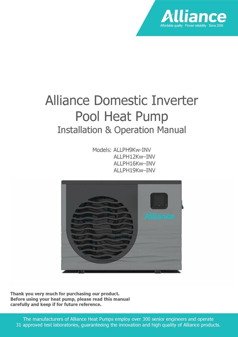
ALLIANCE ALLPH35R410 User manual

Thank you very much for purchasing our product. Before using your unit, please read this manual carefully and keep it for future reference.
SWIMMING POOL
HEAT PUMP
INSTALLATION & OPERATION MANUAL

CONTENTS
1. PREFACE 1
2. Specifications 2
2.1 Performance Data of Swimming Pool Heat Pump Unit 2
2.2 Dimensions for Swimming Pool Heat Pump Unit 3
3. INSTALLATION AND CONNECTION 5
3.1 Installation of System 5
3.2 Swimming Pool Heat Pumps Location 6
3.3 How Close to Your Pool? 6
3.4 Swimming Pool Heat Pumps Plumbing 7
3.5 Swimming Pool Heat Pumps Electrical Wiring 8
3.6 Initial Start-up of the Unit 8
4. USAGE AND OPERATION 9
4.1 Function of the controller 9
4.2 Controller usage 11
4.3 Parameter table 17
5. MAINTENANCE AND INSPECTION 18
5.1 Maintenance 18
5.2 Trouble Shooting 19
6. APPENDIX 20
6.1 Connection of PCB llustration 20
6.2 Cable specification 21
WARRANTY 23

1
1. PREFACE
• In order to provide our customers with quality, reliability and versatility, this product has been made to strict production standards.
This manual includes all the necessary information about installation, fault finding, discharging and maintenance. Please read this manual
carefully before you open or maintain the unit. The manufacturer of this product will not be held responsible if someone is injured or the
unit is damaged, as a result of improper installation, fault finding, or unnecessary maintenance. lt is vital that the instructions within this
manual are adhered to at all times.
The unit must be installed by an Alliance approved installer.
• The unit can only be repaired by an authorised dealer.
• Maintenance and operation must be carried out according to the recommended time and frequency, as stated in this manual.
• Use genuine standard spare parts only.
Failure to comply with these recommendations will invalidate the warranty.
Our heat pump has following characteristics:
1 DURABLE
The heat exchanger is made of PVC &Copper Nickle tube which can withstand prolonged exposure to swimming pool water.
2 QUIET OPERATION
The unit comprises an efficient rotary/ scroll compressor and a low-noise fan motor, which guarantees its quiet operation.
3 ADVANCED CONTROLLING
The unit includes micro-computer controlling, allowing all operation parameters to be set. Operation status can be displayed on the
LED wire controller.

2
2. SPECIFICATIONS
2.1 PERFORMANCE DATA OF SWIMMING POOL HEAT PUMP UNIT
***REFRIGERANT: R410A
UNIT ALLPH35R410 ALLPH54R410 ALLPH76R410
HEATING CAPACITY kW 3.5 5.4 7.6
(24/19-C) Btu/h 11900 18360 25840
HEATING POWER INPUT kW 0.76 1.06 1.52
RUNNING CURRENT A 3.5 4.9 6.8
POWER SUPPLY 230V~/50Hz 230V~/50Hz 230V~/50Hz
COMPRESSOR QUANTITY 1 1 1
COMPRESSOR rotary rotary rotary
FAN NUMBER 1 1 1
FAN POWER INPUT w 90 90 60
FAN ROTATE SPEED RPM 850 850 840
FAN DIRECTION horizontal horizontal horizontal
NOISE dB(A) 48 48 50
WATER CONNECTION mm 50 50 50
WATER FLOW VOLUME m'/h 1.5 2.3 2.8
WATER PRESSURE DROP(MAX) kPa 1.3 1.3 2.5
NET WEIGHT kg 35 37 55
MAXIMUM SET TEMPERATURE °C 43 43 43
Heating: Outdoor air temp: 24"C/19°C, Inlet watertemp:26°C
UNIT ALLPH100R410 ALLPH130R410 ALLPH160R410
HEATING CAPACITY kW 10.0 13.0 16.0
(24/19-C) Btu/h 34000 44200 54400
HEATING POWER INPUT kW 2.02 2.43 2.90
RUNNING CURRENT A 9.1 12.2 12.7
POWER SUPPLY 230V~/50Hz 230V~/50Hz 230V~/50Hz
COMPRESSOR QUANTITY 1 1 1
COMPRESSOR rotary rotary rotary
FAN NUMBER 1 1 1
FAN POWER INPUT w 60 60 80
FAN ROTATE SPEED RPM 840 840 830
FAN DIRECTION horizontal horizontal horizontal
NOISE dB(A) 51 51 53
WATER CONNECTION mm 50 50 50
WATER FLOW VOLUME m'/h 2.8 5.3 5.0
WATER PRESSURE DROP(MAX) kPa 1.8 6.3 4.1
NET WEIGHT kg 35 37 55
MAXIMUM SET TEMPERATURE °C
43 43 43
Heating: Outdoor air temp: 24°C/19°C, Inlet watertemp:26°C

3
2. SPECIFICATIONS
ALLPH35R410/ALLPH54R410 unit: mm
MODEL / MARK ALLPH35R410 / ALLPH54R410
A580
B765
C400
D295
E280
F270
G95
2.2 DIMENSIONS FOR THE SWIMMING POOL HEAT PUMP UNIT
ßÔÔÐØíëÎìïðñßÔÔÐØëìÎìïð
Ó±¼»´
Ó¿®µ ßÔÔÐØíëÎìïðñßÔÔÐØëìÎìïð
ëèð
éêë
ìðð
îçë
îèð
îéð
çë
ß
Þ
Ý
Ü
Û
Ú
Ù
Þ
Ý

4
2. SPECIFICATIONS
ALLPH76R410 / ALLPH 1OOR410 / ALLPH 130R410 / ALLPH 160R410 unit: mm
MODEL / MARK ALLPH76R410/ALLPH 1OOR410
/ ALLPH130R410
ALLPH160R410
A600 871
B956 1116
C545 790
D382 470
E360 447
F350 400
G98 103
2.2 DIMENSIONS FOR THE SWIMMING POOL HEAT PUMP UNIT
ßÔÔÐØéêÎìïðñßÔÔÐØïððÎìïðñßÔÔÐØïíðÎìïðñßÔÔÐØïêðÎìïð
Ó±¼»´
Ó¿®µ
ßÔÔÐØéêÎìïðñßÔÔÐØïððÎìïð
ñßÔÔÐØïíðÎìïð
ßÔÔÐØïêðÎìïð
ß
Þ
Ý
Ü
Û
Ú
Ù
Þ
Ý
èéï
ïïïê
éçð
ìéð
ììé
ìðð
ïðí
êðð
çëê
ëìë
íèî
íêð
íëð
çè

5
3.INSTALLATION AND CONNECTION
INSTALLATION ITEMS:
Alliance only provides the main unit; the other items in the illustration are necessary spare parts for the water system , that the installer must
provide.
ATTENTION:
Please follow these steps when using for the first time
1. 0pen valve and charge water.
2. Make sure thatthe pump and the water-in pipe have been filled with water.
3. Close the valve and start the unit.
The schematic diagram is for reference only. Please check the water inlet/outlet label on the heat pump while plumbing installation.
3.1 INSTALLATION ILLUSTRATION
íòï ײ¬¿´´¿¬·±² ·´´«¬®¿¬·±²
ײ¬¿´´¿¬·±² ·¬»³æ
̸» º¿½¬±®§ ±²´§ °®±ª·¼» ¬¸» ³¿·² «²·¬ ¿²¼ ¬¸» ©¿¬»® «²·¬å ¬¸» ±¬¸»® ·¬»³ ·² ¬¸» ·´´«¬®¿¬·±²
¿®» ²»½»¿®§ °¿®» °¿®¬ º±® ¬¸» ©¿¬»® §¬»³ ô¬¸¿¬ °®±ª·¼»¼ ¾§ «»® ±® ¬¸» ·²¬¿´´»®ò
߬¬»²¬·±²æ
д»¿» º±´´±© ¬¸»» ¬»° ©¸»² «·²¹ º±® ¬¸» º·®¬ ¬·³»
ïòѰ»² ª¿´ª» ¿²¼ ½¸¿®¹» ©¿¬»®ò
îòÓ¿µ» «®» ¬¸¿¬ ¬¸» °«³° ¿²¼ ¬¸» ©¿¬»®ó·² °·°» ¸¿ª» ¾»»² º·´´»¼ ©·¬¸ ©¿¬»®ò
íòÝ´±» ¬¸» ª¿´ª» ¿²¼ ¬¿®¬ ¬¸» «²·¬ò
ßÌÌÒæ ׬ · ²»½»¿®§ ¬¸¿¬ ¬¸» ©¿¬»®ó·² °·°» · ¸·¹¸»® ¬¸¿² ¬¸» °±±´ «®º¿½»ò
̸» ½¸»³¿¬·½ ¼·¿¹®¿³ · º±® ®»º»®»²½» ±²´§ò д»¿» ½¸»½µ ¬¸» ©¿¬»® ·²´»¬ñ±«¬´»¬ ´¿¾»´ ±² ¬¸»
¸»¿¬ °«³° ©¸·´» °´«³¾·²¹ ·²¬¿´´¿¬·±²ò

6
3.INSTALLATION AND CONNECTION
3.3 HOW CLOSE TO YOUR POOL?
Normally , the longer the distance from the pool, the greater the heat loss from the piping.
It is recommended to install the heat pump near the pool.
The unit will perform well in any outdoor location provided that the following three factors are present .
1. Fresh Air - 2. Electricity - 3. filter piping
DO NOT place the unit in an enclosed area with a limited air volume, where the heat pumps discharge air will be re-circulated.
DO NOT place shrubs in front of the heat pump which can block air inlet.
These locations deny the unit of a continuous source of fresh air which reduces it eciency and may prevent adequate heat delivery.
3.2 SWIMMING POOL HEAT PUMPS LOCATION
̸» «²·¬ ©·´´ °»®º±®³ ©»´´ ·² ¿²§ ±«¬¼±±® ´±½¿¬·±² °®±ª·¼»¼ ¬¸¿¬ ¬¸» º±´´±©·²¹ ¬¸®»» º¿½¬±® ¿®»
°®»»²¬ ò
ïò Ú®»¸ ß·® ó îò Û´»½¬®·½·¬§ ó íò º·´¬»® °·°·²¹
ÜÑ ÒÑÌ °´¿½» ¬¸» «²·¬ ·² ¿² »²½´±»¼ ¿®»¿ ©·¬¸ ¿ ´·³·¬»¼ ¿·® ª±´«³»ô ©¸»®» ¬¸» «²·¬
¼·½¸¿®¹» ¿·® ©·´´ ¾» ®»ó½·®½«´¿¬»¼ò
ÜÑ ÒÑÌ °´¿½» ¬¸» «²·¬ ¬± ¸®«¾ ©¸·½¸ ½¿² ¾´±½µ ¿·® ·²´»¬ò ̸»»
´±½¿¬·±² ¼»²§ ¬¸» «²·¬ ±º ¿ ½±²¬·²«±« ±«®½» ±º º®»¸ ¿·® ©¸·½¸ ®»¼«½» ·¬ »ºº·½·»²½§ ¿²¼
³¿§ °®»ª»²¬ ¿¼»¯«¿¬» ¸»¿¬ ¼»´·ª»®§ò
íòî Í©·³³·²¹ б±´ Ø»¿¬ Ы³° Ô±½¿¬·±²
íòí Ø±© Ý´±» ̱ DZ«® б±´á
Ò±®³¿´´§ô ¬¸» ´±²¹»® ¬¸» ¼·¬¿²½» º®±³ ¬¸» °¿ô ¬¸» ¹®»¿¬»® ¬¸» ¸»¿¬ ´± º®±³ ¬¸» °·°·²¹ò ׬
· ®»½±³³»²¼»¼ ¬± ·²¬¿´´ ¬¸» ¸»¿¬ °«³° ²»¿® ¬¸» °¿ò
ß·® ·²´»¬
ß·® ±«¬´»¬

7
3.INSTALLATION AND CONNECTION
3.4 SWIMMING POOL HEAT PUMPS PLUMBING
Location: Connect the unit in the pool pump discharge(return) line downstream of the filter and pool pumps, and upstream of any chlorinators,
ozonatorsor chemical pumps.
Standard model have slip glue fittings which accept 32mm or 50 mm PVC pipe for connection to the pool or spa filtration piping. By using a
50NB to 40NB you can plumb 40NB PVC piping straight into the unit.
Give serious consideration to adding a quick coupler fitting at the unit inlet and outlet to allow easy draining of unit for winterizing and to
provide easier access should servicing be required.
Condensation: Since the Heat pump cools down the air about 4 -5°C, water may condense on the fins of the evaporator. lf the relative
humidity is very high, this could be as much as several litres an hour. The water will run down the fins into the base pan and drain out through
the plastic condensation drain fitting on the side of the base pan. This fitting is designed to accept 20mm clear vinyl tubing which can be
pushed on by hand and run to a suitable drain. It is easy to mistake the condensation for a water leak inside the unit.
Ô±½¿¬·±²æ ݱ²²»½¬ ¬¸» «²·¬ ·² ¬¸» °±±´ °«³° ¼·½¸¿®¹» ø®»¬«®²÷ ´·²» ¼±©²¬®»¿³ ±º ¿´´ º·´¬»®
¿²¼ °±±´ °«³°ô ¿²¼ «°¬®»¿³ ±º ¿²§ ½¸´±®·²¿¬±®ô ±¦±²¿¬±® ±® ½¸»³·½¿´ °«³°ò
ͬ¿²¼¿®¼ ³±¼»´ ¸¿ª» ´·° ¹´«» º·¬¬·²¹ ©¸·½¸ ¿½½»°¬ íî³³ ±® ëð ³³ ÐÊÝ °·°» º±®
½±²²»½¬·±² ¬± ¬¸» °±±´ ±® °¿ º·´¬®¿¬·±² °·°·²¹ò Þ§ «·²¹ ¿ ëð ÒÞ ¬± ìðÒÞ §±« ½¿² °´«³¾ ìðÒÞ
ÐÊÝ °·°·²¹ ¬®¿·¹¸¬ ·²¬± ¬¸» «²·¬ò
Ù·ª» »®·±« ½±²·¼»®¿¬·±² ¬± ¿¼¼·²¹ ¿ ¯«·½µ ½±«°´»® º·¬¬·²¹ ¿¬ ¬¸» «²·¬ ·²´»¬ ¿²¼ ±«¬´»¬ ¬± ¿´´±©
»¿§ ¼®¿·²·²¹ ±º «²·¬ º±® ©·²¬»®·¦·²¹ ¿²¼ ¬± °®±ª·¼» »¿·»® ¿½½» ¸±«´¼ »®ª·½·²¹ ¾»
®»¯«·®»¼ò
ݱ²¼»²¿¬·±²æ Í·²½» ¬¸» Ø»¿¬ °«³° ½±±´ ¼±©² ¬¸» ¿·® ¿¾±«¬ ì óë ô ©¿¬»® ³¿§ ½±²¼»²» ±²
¬¸» º·² ±º ¬¸» ¸±®»¸±» ¸¿°»¼ »ª¿°±®¿¬±®ò ׺ ¬¸» ®»´¿¬·ª» ¸«³·¼·¬§ · ª»®§ ¸·¹¸ô ¬¸· ½±«´¼
¾» ¿ ³«½¸ ¿ »ª»®¿´ ´·¬®» ¿² ¸±«®ò ̸» ©¿¬»® ©·´´ ®«² ¼±©² ¬¸» º·² ·²¬± ¬¸» ¾¿»°¿² ¿²¼
¼®¿·² ±«¬ ¬¸®±«¹¸ ¬¸» ¾¿®¾»¼ °´¿¬·½ ½±²¼»²¿¬·±² ¼®¿·² º·¬¬·²¹ ±² ¬¸» ·¼» ±º ¬¸» ¾¿»°¿²ò
̸· º·¬¬·²¹ · ¼»·¹²»¼ ¬± ¿½½»°¬ îð³³ ½´»¿® ª·²§´ ¬«¾·²¹ ©¸·½¸ ½¿² ¾» °«¸»¼ ±² ¾§ ¸¿²¼
¿²¼ ®«² ¬± ¿ «·¬¿¾´» ¼®¿·²ò ׬ · »¿§ ¬± ³·¬¿µ» ¬¸» ½±²¼»²¿¬·±² º±® ¿ ©¿¬»® ´»¿µ ·²·¼» ¬¸»
«²·¬ò
ÒÞæ ß ¯«·½µ ©¿§ ¬± ª»®·º§ ¬¸¿¬ ¬¸» ©¿¬»® · ½±²¼»²¿¬·±² · ¬± ¸«¬ ±ºº ¬¸» «²·¬ ¿²¼ µ»»° ¬¸»
°±±´ °«³° ®«²²·²¹ò ׺ ¬¸» ©¿¬»® ¬±° ®«²²·²¹ ±«¬ ±º ¬¸» ¾¿»°¿²ô ·¬ · ½±²¼»²¿¬·±²ò ßÒ
ÛÊÛÒ ÏË×ÝÕÛÎ ÉßÇ ×Í ¬± ÌÛÍÌ ÌØÛ ÜÎß×Ò ÉßÌÛÎ ÚÑÎ ÝØÔÑÎ×ÒÛ ó ·º ¬¸» · ²± ½¸´±®·²»
°®»»²¬ô ¬¸»² ·¬ù ½±²¼»²¿¬·±²ò
̸» Í©·³³·²¹ б±´ Ø»¿¬ Ы³° »¨½´«·ª» ®¿¬»¼ º´±© ¬·¬¿²·«³ ¸»¿¬ »¨½¸¿²¹»® ®»¯«·®» ²±
°»½·¿´ °´«³¾·²¹ ¿®®¿²¹»³»²¬ »¨½»°¬ ¾§°¿ø°´»¿» »¬ ¬¸» º´±© ®¿¬» ¿½½±®¼·²¹ ¬± ¬¸»
²¿³»°´¿¬»÷ò ̸» ©¿¬»® °®»«®» ¼®±° · ´» ¬¸¿² ïðµÐ¿ ¿¬ ³¿¨ò Ú´±© ®¿¬»ò Í·²½» ¬¸»®» · ²±
®»·¼«¿´ ¸»¿¬ ±® º´¿³» Ì»³°»®¿¬«®»ô ̸» «²·¬ ¼±» ²±¬ ²»»¼ ½±°°»® ¸»¿¬ ·²µ °·°·²¹ò ÐÊÝ
°·°» ½¿² ¾» ®«² ¬®¿·¹¸¬ ·²¬± ¬¸» «²·¬ò

8
3.INSTALLATION AND CONNECTION
3.5 SWIMMING POOL HEAT PUMPS ELECTRICAL WIRING
NOTE: Although the unit heat exchanger is electrically isolated from the rest of the unit, it simply prevents the flow of electricity to or from the
pool water. Grounding the unit is still required to protect you against short circuits inside the unit. Bonding is also required.
The unit has a separate molded-injunction box with a standard electrical conduit nipple already in place. Just remove the screws and the
front panel, feed your supply lines in through the conduit nipple and wire-nut the electric supply wires to the three connections already in
the junction box (four connections if three phase). To complete electrical hookup, connect Heat Pump by electrical conduit, U F cable or other
suitable means as specified (as permitted by local electrical authorities) to a dedicated AC power supply branch circuit equipped with the
proper circuit breaker.
3.6 INITIAL STARTUP OF THE UNIT
NOTE- In order for the unit to heat the pool or spa, the filter pump must be running to circulate water through the heat exchanger.
Start up Procedure - After installation is completed, you should follow these steps:
1. Turn on your pool pump. Check for water leaks and verify flow to and from the pool.
2. Turn on the electrical power supply to the unit, then press the key ON/OFF of wire controller, lt should start in several seconds.
3. After running a few minutes make sure the air leaving the top (side) of the unit is
cooler(Between 5-10 "C)
4. With the unit operating turn the filter pump o. The unit should also turn o automatically,
5. Allow the unit and pool pump to run 24 hours per day until desired pool water temperature is reached. When the water-in temperature
reaches set temperature, the unit shuts o. The unit will now automatically restart (as long as your pool pump is running) when the pool
temperature drops more than 2°C below set temperature.
Time Delay - The unit is equipped with a 3 minute built-in solid state restart delay included to protect control circuit components and to
eliminate restart cycling and contactor chatter. This time delay will automatically restart the unit approximately 3 minutes after each control
circuit interruption. Even a brief power interruption will activate the solid state 3 minute restart delay and prevent the unit from starting until
the 5 minute countdown is completed. Power interruptions during the delay period will have no eect on the 3 minute countdown.

9
4. USAGE AND OPERATION
4.1 FUNCTION OF CONTROLLER
1. BUTTON FUNCTION
# SYMBOL NAME FUNCTION
1On/o Press this button to start up or shut down the unit, cancel the current operation or go back to the
previous interface
2Mode Press this button to switch modes or save the parameter setting.
3Clock Press this button to set the clock and timer
4Up Press this button to move up or increase parameter value.
5Down Press this button to move down or decrease the parameter value.
ìò ËÍßÙÛ ßÒÜ ÑÐÛÎßÌ×ÑÒ
ìòï Ú«²½¬·±² ±º ½±²¬®±´´»®
Ó¿·² ¼·°´¿§ ¿®»¿
ß«¨ò Ü·°´¿§ ¿®»¿
ï
î
í
ì
ïìë
í
ß
î
Ý´±½µ
ïÞ«¬¬±² º«²½¬·±²
ÒÑ Í§³¾±´ Ò¿³» Ú«²½¬·±²
Ѳ񱺺
Ó±¼»
˰
Ю» ¬¸· ¾«¬¬±² ½¿² ¬¿®¬ «° ±® ¸«¬ ¼±©² ¬¸» «²·¬ô
½¿²½»´ ¬¸» ½«®®»²¬ ±°»®¿¬·±² ±® ¾¿½µ ¬± ¬¸» «°°»®
·²¬»®º¿½»
Ю» ¬¸· ¾«¬¬±² ½¿² ©·¬½¸ ³±¼» ±® ¿ª»
°¿®¿³»¬»® »¬¬·²¹ò
Ю» ¬¸· ¾«¬¬±² ½¿² ³±ª» «° ±® ·²½®»¿»
°¿®¿³»¬»® ª¿´«»ò
Ю» ¬¸· ¾«¬¬±² ½¿² ³±ª» ¼±©² ±® ¼»½®»¿» ¬¸»
°¿®¿³»¬»® ª¿´«»ò
ܱ©²
ë
Ю» ¬¸· ¾«¬¬±² ½¿² »¬ ¬¸» ½´±½µ ¿²¼ ¬·³»®

10
4. USAGE AND OPERATION
2. DISPLAY FUNCTION
SYMBOL MEANING FUNCTION
Cooling Unit is in cooling mode.
Heating Unit is in heating mode and flashes when defrosting.
Automatic Unit is in automatic mode.
Electric-heating Unit is in electric-heating mode. (Swimming pool unit without this display)
Timer on Sets the timer on
Timer o Sets the timer o
Inlet water Main display area displays the inlet water temperature. (measured value)
Outlet water AUX display area displays the outlet water temperature. (measured value)
Temperature Main/ AUX display area displays the temperature
Flow Main display area displays the water flow value
Minute Main display area displays minute value
Fahrenheit Main/AUX display area displays Fahrenheit value
Centigrade Main/AUX display area displays Centigrade value
Parameter setting Parameter can be set.
Lock Keyboard is locked.

11
4. USAGE AND OPERATION
4.2 CONTROLLER USAGE
2.1 Starting up and shutting down
In the o interface, press " " for 0.5 scan start up the unit, and aux. display-area shows water outlet temperature; In the running interface, press " "
for 0.5s can shut down the unit and aux. display-area shows "OFF" .
Attention: the operation of Starting up and shutting down can only be done in the main interface. For example:
2.2 Modes switching
In the main interface, you can switch dierent modes of cooling, heating, auto mode by pressing " ".
ìò ËÍßÙÛ ßÒÜ ÑÐÛÎßÌ×ÑÒ
ìòî ̸» ½±²¬®±´´»® «¿¹»
îòï
ͬ¿®¬·²¹ «° ¿²¼ ¸«¬¬·²¹ ¼±©²
Ю»
º±® ðòë »½±²¼
½¿² ©·¬½¸
¾»¬©»»² «²·¬
±² ¿²¼ «²·¬ ±ºº
É¿¬»® ±«¬´»¬
¬»³°»®¿¬«®»
ß½¬«¿´ Ó±¼» ¼·°´¿§
Ѻº «²·¬
îòî Ó±¼» ©·¬½¸·²¹
׺ ·¬ · ½±´¼ñ ¸»¿¬ «²·¬ô ·² ¬¸» ³¿·² ·²¬»®º¿½»ô §±« ½¿² ©·¬½¸ ¼·ºº»®»²¬ ³±¼» ±º ½±±´·²¹ô
¸»¿¬·²¹ô ¿«¬± ³±¼» ¾§ °®»·²¹ ò
߬¬»²¬·±² ̸» ³±¼» ©·¬½¸·²¹ · «»´» ·º ¬¸» «²·¬ §±« ¾«§ · ·²¹´»ó½±´¼ñ ·²¹´»ó¸»¿¬ «²·¬ò
Ú±® »¨¿³°´»æ
Ю» Ю»
Ю»
Ю»
ß
ײ ¬¸» ±ºº ·²¬»®º¿½»ô °®»þ þ º±® ðòë ½¿² ¬¿®¬ «° ¬¸» «²·¬ô ¿²¼ ¿«¨ò ¼·°´¿§ó¿®»¿ ¸±©
©¿¬»® ±«¬´»¬ ¬»³°»®¿¬«®»å ײ ¬¸» ®«²²·²¹ ·²¬»®º¿½»ô °®»þ þ º±® ðòë ½¿² ¸«¬ ¼±©² ¬¸» «²·¬
¿²¼ ¿«¨ò ¼·°´¿§ó¿®»¿ ¸±© ÑÚÚ ò
߬¬»²¬·±²æ ¬¸» ±°»®¿¬·±² ±º ͬ¿®¬·²¹ «° ¿²¼ ¸«¬¬·²¹ ¼±©² ½¿² ±²´§ ¾» ¼±²» ·² ¬¸» ³¿·² ·²¬»®º¿½»ò
Ú±® »¨¿³°´»æ
ß½¬«¿´ Ó±¼» ¼·°´¿§
É¿¬»® ·²´»¬
¬»³°»®¿¬«®» É¿¬»® ±«¬´»¬
¬»³°»®¿¬«®»
Ѳ «²·¬

12
4. USAGE AND OPERATION
2.3 Temperature setting
In the main interface , press " " or " " for the current mode target-temperature to flash, then press " " to increase the temp. value, or press " " to
decrease it. Press " " to save the setting parameter and go back to the main interface; Pressing " " can not save setting parameter but goes back
to the main interface.
Attention: If there is no operation for 5s, the system will remember the parameter setting and go back to the main interface.
2.4 Clock setting
In the main interface, press " " twice, Hours start to flash, and press " " to increase value or press " " to decrease value, and press " " to save
setting; At the same time, minute start to flashing , press " " to increase value or press " " to decrease value, and press " " to save setting.
Press " " can not save setting parameter and back to main interface.
Attention: If there is no operation for 5s system will remember parameter setting and back to the main interface.
For example,
ìò ËÍßÙÛ ßÒÜ ÑÐÛÎßÌ×ÑÒ
îòí Ì»³°»®¿¬«®» »¬¬·²¹
Ю»
±®
Ю»
±® ¬± ½¸¿²¹» ¬¸» ª¿´«»
Ю»
¬± ¿ª» ª¿´«»
»¬¬·²¹
ݱ±´·²¹ ¬¿®¹»¬ ¬»³°»®¿¬«®»
îòì Ý´±½µ »¬¬·²¹
ײ ¬¸» ³¿·² ·²¬»®º¿½» °®» ¬©·½» ر«® ¬¿®¬ ¬± º´¿¸·²¹ ¿²¼ °®»
¬± ·²½®»¿» ª¿´«» ±® °®» ¬± ¼»½®»¿» ª¿´«» ¿²¼ °®» ¬± ¿ª» »¬¬·²¹
߬ ¬¸» ¿³» ¬·³»ô ³·²«¬» ¬¿®¬ ¬± º´¿¸·²¹ °®» ¬± ·²½®»¿» ª¿´«» ±® °®»
¬± ¼»½®»¿» ª¿´«» ¿²¼ °®» ¬± ¿ª» »¬¬·²¹ò
Ю» ½¿² ²±¬ ¿ª» »¬¬·²¹ °¿®¿³»¬»® ¿²¼ ¾¿½µ ¬± ³¿·² ·²¬»®º¿½»ò
߬¬»²¬·±² ׺ ¬¸»®» · ²± ±°»®¿¬·±² º±® ë §¬»³ ©·´´ ®»³»³¾»® °¿®¿³»¬»® »¬¬·²¹ ¿²¼ ¾¿½µ
¬± ¬¸» ³¿·² ·²¬»®º¿½»ò
Ú±® »¨¿³°´»
ײ ¬¸» ³¿·² ·²¬»®º¿½» °®» ±® ¿²¼ ¬¸» ½«®®»²¬ ³±¼» ¬¿®¹»¬ó¬»³°»®¿¬«®»
º´¿¸»ô ¬¸»² °®» ¬± ·²½®»¿» ¬¸» ¬»³°òª¿´«»ô ±® °®» ¬± ¼»½®»¿» ·¬ò
Ю» ½¿² ¿ª» »¬¬·²¹ °¿®¿³»¬»® ¿²¼ ¾¿½µ ¬± ¬¸» ³¿·² ·²¬»®º¿½»
Ю» ½¿² ²±¬ ¿ª» »¬¬·²¹ °¿®¿³»¬»® ¾«¬ ¾¿½µ ¬± ¬¸» ³¿·² ·²¬»®º¿½»
߬¬»²¬·±² ׺ ¬¸»®» · ²± ±°»®¿¬·±² º±® ë §¬»³ ©±«´¼ ®»³»³¾»® °¿®¿³»¬»® »¬¬·²¹ ¿²¼
¾¿½µ ¬± ¬¸» ³¿·² ·²¬»®º¿½»ò
Ú±® »¨¿³°´»æ

13
4. USAGE AND OPERATION
ìò ËÍßÙÛ ßÒÜ ÑÐÛÎßÌ×ÑÒ
Ю»
ر«® ³·²«¬» Ú´¿¸·²¹
Ú´¿¸·²¹
Ю»
Ю»
±®
Ю»
¬± ¿ª» ¸±«®
ª¿´«» »¬¬·²¹
Ю»
±®
Ю»
¬± ¿ª» ³·²«¬» ª¿´«» »¬¬·²¹
Ú´¿¸·²¹
Ú´¿¸·²¹ Ú´¿¸·²¹

14
4. USAGE AND OPERATION
2.5 Timersetting
In the main interface, press " " and hold for 2 seconds until "on" flashes, Now you can set the timer on (means the unit timer is on),
then press " " again and hold for 2 seconds until "o" flashes. Now you can set the timer o (means the unit timer is o) .
If you want to cancel the timer o, In the "o" flashing interface, press" " to cancel.
Attention
1) If there is no operation for 5s, system will remember clock setting and go back to the main interface.
2) By pressing" " till "o" flashes, you can set the timer o without timer on.
ìò ËÍßÙÛ ßÒÜ ÑÐÛÎßÌ×ÑÒ
îòë Ì·³»® »¬¬·²¹
ײ ¬¸» ³¿·² ·²¬»®º¿½» °®» ¸±´¼ ±² î »½±²¼ ¿²¼ þ±²þ · º´¿¸·²¹ô ¿¬ ¬¸· ¬·³»ô
§±« ½¿² »¬ ¬¸» ¬·³»® ±² ³»¿² ¬¸» «²·¬ ¬·³»® · ±² ¬¸»² °®» ¿¹¿·² ¿²¼ ¸±´¼ ±²
î »½±²¼ ¿²¼ þ±ººþ · º´¿¸» §±« ½¿² »¬ ¬¸» ¬·³»® ±ºº ³»¿² ¬¸» «²·¬ ¬·³»® · ±ºº ò
׺ §±« ©¿²¬ ½¿²½»´ ¬¸» ¬·³»® ±ººô ײ ¬¸» þ±ººþ º´¿¸·²¹ ·²¬»®º¿½» °®» ¬± ½¿²½»´
߬¬»²¬·±² ï÷ ׺ ¬¸»®» · ²± ±°»®¿¬·±² º±® ë §¬»³ ©·´´ ®»³»³¾»® ½´±½µ »¬¬·²¹ ¿²¼ ¾¿½µ ¬±
¬¸» ³¿·² ·²¬»®º¿½»ò
î÷ Þ§ °®»·²¹ þ þ ¬·´´ ¬¸» þ±ººþ º´¿¸·²¹ô §±« ½¿² »¬ ¬¸» ¬·³»® ±ºº ©·¬¸±«¬ ¬·³»® ±²ò
Ю»
º±® î »½±²¼
Ю»
Ú´¿¸·²¹
Ú´¿¸·²¹Ú´¿¸·²¹
°®»
±®
Ю»
Ú´¿¸·²¹ Ú´¿¸·²¹
°®»
±® Ю»

15
4. USAGE AND OPERATION
ìò ËÍßÙÛ ßÒÜ ÑÐÛÎßÌ×ÑÒ
Ú´¿¸·²¹
Ю»
Ю»
±®
Ю»
Ю»
±®
Ю»
̸» ¬·³»® ±² ¿²¼ ±ºº ¸¿ ¾»»² »¬
Ú´¿¸·²¹ Ú´¿¸·²¹
Ú´¿¸·²¹ Ú´¿¸·²¹ Ú´¿¸·²¹ Ú´¿¸·²¹
Ú´¿¸·²¹ Ú´¿¸·²¹

16
4. USAGE AND OPERATION
2.6 Cancel the timer setting
Press" " for 2s until "ON" is flashing, Now press " " to cancel the setting of timer on; It is the same way to cancel the setting of timer o .
For example:
ìò ËÍßÙÛ ßÒÜ ÑÐÛÎßÌ×ÑÒ
îòê Ý¿²½»´ ¬¸» ¬·³»® »¬¬·²¹
Ю» º±® î ¿²¼ þÑÒþ · º´¿¸·²¹ ¿¬ ¬¸· ¬·³»ô °®»
¬± ½¿²½»´ ¬¸» »¬¬·²¹
±º ¬·³»® ±²å ׬ · ¬¸» ¿³» ©¿§ ¬± ½¿²½»´ ¬¸» »¬¬·²¹ ±º ¬·³»® ±ºº ò
Ú±® »¨¿³°´»
̸» ¬·³»® ±²ñ±ºº ¸¿ ¾»»² »¬
Ю»
º±® î
þÑÒþ · º´¿¸·²¹
̸» »¬¬·²¹ ±º ¬·³»® ±² ¸¿
¾»»² ½¿²½»´´»¼
Ю»
Ю»
º±® ì
þÑÚÚþ · º´¿¸·²¹
̸» »¬¬·²¹ ±º ¬·³»® ±ºº ¸¿
¾»»² ½¿²½»´´»¼
Ю»

17
4. USAGE AND OPERATION
2.4 Keyboard lock
To avoid mis-operation, please lock the controller after parameter setting. At the main interface, press" " for 5 seconds, the keyboard will be locked.
When the keyboard is locked, press" " for 5 seconds, the keyboard will be unlocked.
2.5 Malfunction display
A malfunction code will show on the controller screen when a relative malfunction occurs. You can refer to the malfunction table to find out the
failure cause and solution. For example:
4.3 Parametertable
îòì Õ»§¾±¿®¼ ´±½µ
̱ ¿ª±·¼ ³·ó±°»®¿¬·±²ô °´»¿» ´±½µ ¬¸» ½±²¬®±´´»® ¿º¬»® °¿®¿³»¬»® »¬¬·²¹ò
߬ ¬¸» ³¿·² ·²¬»®º¿½»ô °®» º±® ë »½±²¼ô ¬¸» µ»§¾±¿®¼ ©·´´ ¾» ´±½µ»¼ò
ɸ»² ¬¸» µ»§¾±¿®¼ · ´±½µ»¼ô °®» º±® ë »½±²¼ô ¬¸» µ»§¾±¿®¼ ©·´´ ¾»
«²´±½µ»¼ò
ÒÑÌÛÍæ ɸ»² ¬¸» «²·¬ · ·² ¿´¿®³·²¹ ¬¿¬»ô ¬¸» µ»§ ´±½µ ½¿² ¾» ®»³±ª»¼ ¿«¬±³¿¬·½´§ò
ر´¼ ±²
Ô±½µ»¼
îòë Ó¿´º«²½¬·±² ¼·°´¿§
̸»®» ©·´´ ¾» ³¿´º«²½¬·±² ½±¼» ¸±©·²¹ ±² ¬¸» ½±²¬®±´´»® ½®»»² ©¸»² ®»´¿¬·ª»
³¿´º«²½¬·±² ±½½«®ò
DZ« ½¿² ®»º»® ¬± ¬¸» ³¿´º«²½¬·±² ¬¿¾´» ¬± º·²¼ ±«¬ ¬¸» º¿·´«®» ½¿«» ¿²¼ ±´«¬·±²ò
Ú±® »¨¿³°´»
É¿¬»® ·²´»¬ ¬»³°ò Í»²±® º¿·´«®»
MEANING DEFAULT REMARK
Heating inlet target temp. 27"C Adjustable
Coolinq inlet tarqettemp. 27"C Adjustable
Auto inlet targettemp. 27"C Adjustable

18
5. MAINTENANCE AND INSPECTION
5.1 Maintenance
•
You should avoid no water or air entering into system , as this will influence unit's performance and reliability. You should clear the pool/spa filter
regularly to avoid damage to the unitas a result of the dirty of clogged filter.
•
The area around the unit should be dry, clean and well ventilated.
•
The operation pressure of the refrigerant system should only be serviced by a certified technician .
•
Check the power supply and cable connection often, .Should the unit begin to operate abnormally , switch it o and contact a qualified technician.
•
Discharge all water in the water pump and water system ,so that freezing of the water in the pump or water system does not occur. You should
discharge the water at the bottom of water pump if the unit will not be used for an extended period of time. You should check the unit thoroughly
and fill the system with water fully before using it for the first time after a prolonged period of no usage.
This manual suits for next models
5
Table of contents
Other ALLIANCE Heat Pump manuals
Popular Heat Pump manuals by other brands

Daikin
Daikin ETSHB16P50EF installation manual

Daikin
Daikin Altherma EAVH16S23DA6V Installer's reference guide

Daikin
Daikin FAQ71BVV1B Service manual

Allied Air
Allied Air 4SHP13 series installation instructions

Carrier
Carrier 30RQ 039 Series Installation, operation and maintenance instructions

Goodman
Goodman R-410A installation manual

Rotex
Rotex RHYKOMB33AA Installer's reference guide

Carrier
Carrier 38MARB Installation instruction

Ingersoll-Rand
Ingersoll-Rand ENL 10 Instructions for installation and operation

Carrier
Carrier 38BQ Installation, Start-Up and Service Instructions

LG
LG ARNU12GSER1 owner's manual

Lennox
Lennox Elite XP13018 Service literature