Allied Radio Knight-Kit 83 Y 140 User manual
@®
REGISTERED
TRADEMARK
OF
ALLIED
RADIO
CORP.—100
NORTH
WESTERN
AVENUE,
CHICAGO
80,
ILLINOIS
TELEPHONE
HAYMARKET
1-6800
copyrighted
1956,
by
Allied
Radio
Corp
/
printed
in
U.S.A.
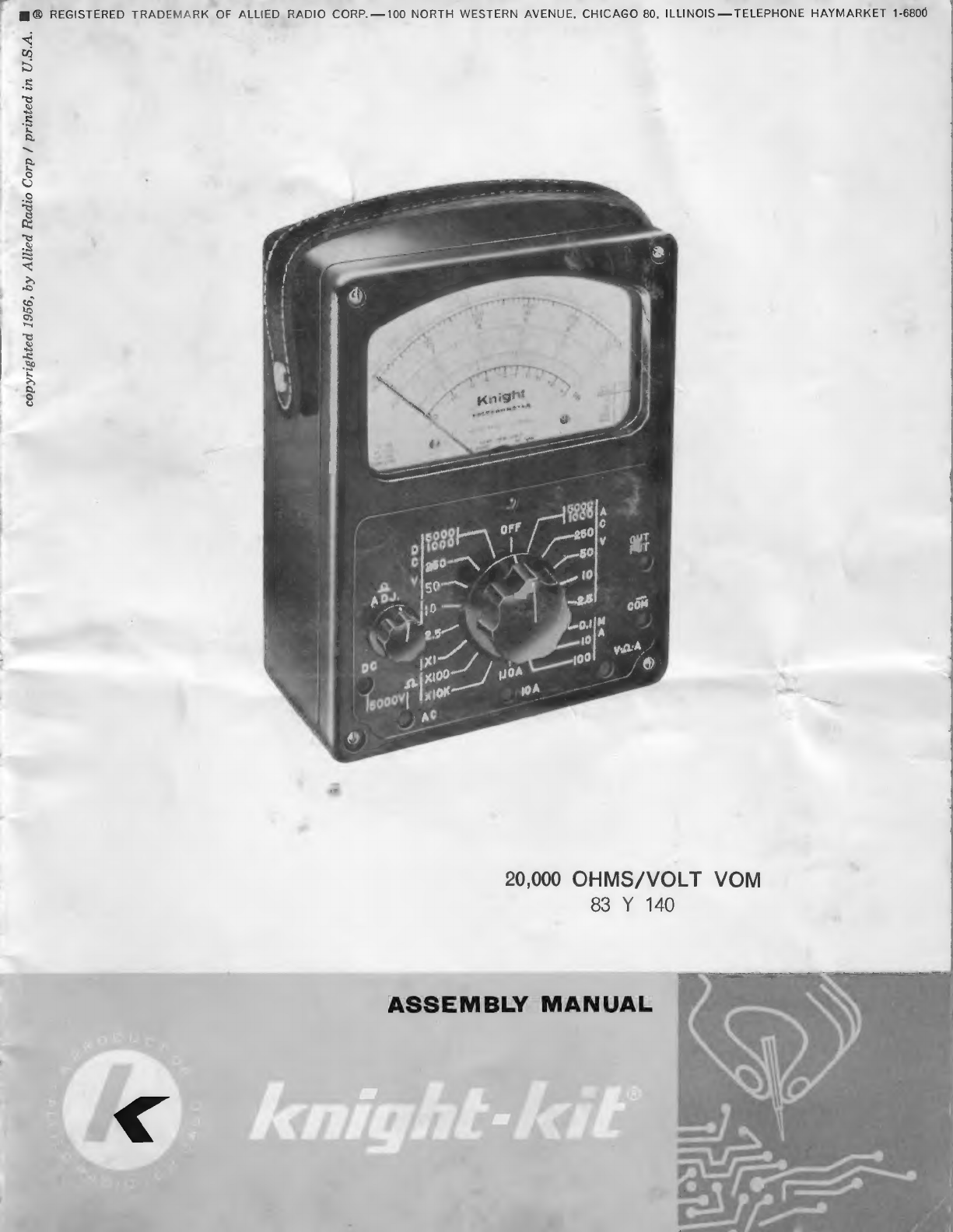
20,000
OHMS/VOLT
VOM
83
Y
140
ASSEMBLY
MANUAL
HOW
TO
BUILD
THE
KNIGHT
VOM
The
improved
circuit
design
of
the
KNIGHT
VOM
assures
a
sensitive
and
accurate
test
instrument
for
the
radio-
TV
serviceman,
the
laboratory
technician,
or
the
amateur.
You
may
measure
any
AC
or
DC
voltage
found
in
radio
and
electronics
work
up
to
5000
volts.
The
input
resistance
for
DC
scales
is
20,000
ohms
per
volt.
This
enables
you
to
read
voltages
in
high
impedance
circuits
with-
out
interfering
with
the
circuit.
For
AC
voltage
measurements
it
is
5000
ohms
per
volt.
Direct
currents
may
be
meas-
ured
up
to
10
amperes.
There
are
three
resistance
ranges.
Center
scale
readings
are
at
12,
1200,
and
120,000
ohms.
All
multipliers
are
1%
precision
resistors,
which
assure
ac-
curate
measurements
for
the
life
of
the
instrument.
Check
all
of
the
parts
against
the
Parts
List
as
you
unpack
the
VOM
kit.
If
you
are
unable
to
identify
some
of
the
parts
by
sight,
locate
them
on
the
pictorial
dia-
grams.
Hardware
is
listed
in
the
last
part
of
the
Parts
List.
To
keep
our
kits
at
the
lowest
possible
price,
we
frequently
weigh
hardware,
rather
than
to
count
it
one
by
one.
Therefore,
do
not
be
concerned
if
more
nuts
and
machine
screws
for
ex~
ample,
are
supplied
than
are
specified
in
the
Parts
List.
The
only
tools
you
will
need
are:
long-
nose
pliers,
diagonal
cutters,
a
screw-
driver,
a
small
set-screw
driver,
and
a
soldering
iron.
Building
your
KNIGHT
20,000
ohms
per
volt
VOM
will
be
easier
if
you
study
all
of
the
diagrams
and
instructions
before
assembly
is
started.
The
pictorial
diagrams
show
the
actual
location
of
all
parts
and
wiring.
The
KNIGHT
VOM
will
work
best
when
all
parts
are
placed
as
shown
in
the
dia-
grams.
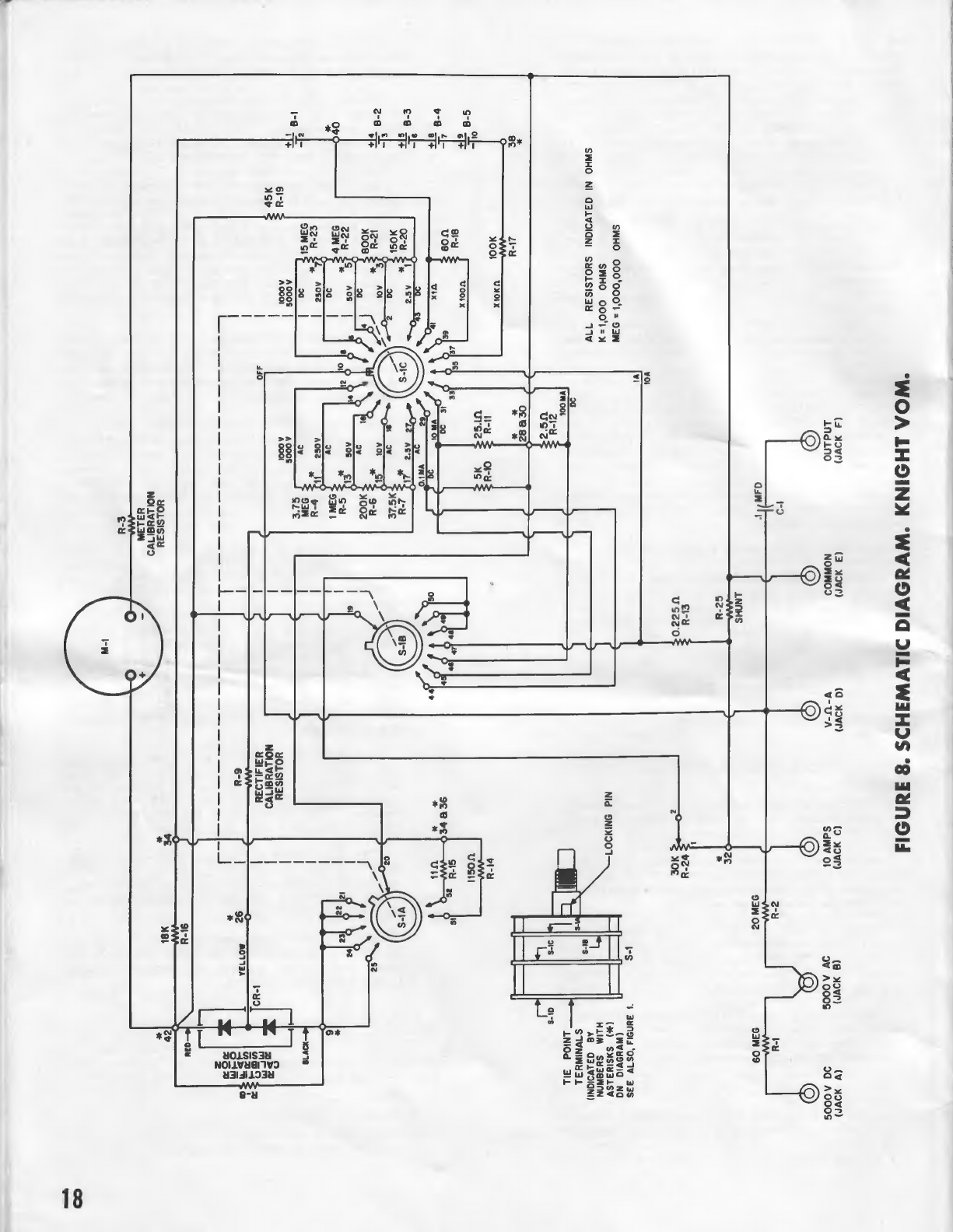
The
schematic
diagram
shows
how
the
parts
are
connected
electrically,
and
is
useful
in
understanding
how
the
instrument
works.
These
step-by-step
instructions
were
prepared
while
actually
building
the
KNIGHT
VOM.
They
are
the
best
and
fastest
way
of
assembling
this
unit.
May
'
we
suggest
that
you
check
off
each
step
after
you
have
completed
it.
Some
build-
ers
also
put
a
pencil
mark
on
the
wiring
views
along
the
leads
and
parts
that
they
have
just
installed.
Both
of
these
methods
are
good
and
will
assure
speedy
and
correct
wiring.
WIRING
AND
SOLDERING
The
quality
of
workmanship
in
test
equipment
will
often
determine
whether
an
instrument
will
be
an
accurate
and
re-
liable
service
tool.
While
these
wiring
and
soldering
hints
will
be
more
helpful
to
a
beginner
in
electronics,
the
more
ex-
perienced
builder
may
also
benefit
by
re-
viewing
them.
Make
good
mechanical
connections
at
joints,
clean
metal
to
clean
metal.
Loop
the
wires
around
the
switch,
other
con-
nection
terminals,
and
clamp
tight.
Cut
the
excess
lengths
of
all
end
leads
of
the
resistors
when
they
are
soldered.
When
a
solder
connection
is
made
close
to
one
of
the
precision
resistors,
hold
the
jaws
of
a
pair
of
long-nose
pliers
on
the
lead
between
the
tip
of
the
soldering
iron
and
the
resistor
to
conduct
the
heat
away
from
the
resistor.
Arrange
the
long
wire
leads
to
lay
close
to
the
panel.
USE
ONLY
ROSIN
CORE
SOLDER.
Use
the
rosin
core
solder
supplied
with
the
kit
as
KITS
WIRED
WITH
ACID
CORE
SOL-
DER
OR
ACID
FLUX
WILL
CORRODE
and
WILL
NOT
WORK
FOR
LONG.
SUCH
KITS
ARE
NOT
ELIGIBLE
FOR
REPAIR
OR
SERVICE.
The
soldering
iron
tip
must
be
well
tinned.
First,
clean
the
tip
with
steel
wool
or
a
fine
file
until
the
bright
copper
shown
in
Figure
6
and
on
the
label.
The
large
‘‘C’’
battery,
B-1,
fits
into
the
space
shown
by
the
dotted
lines
on
the
label.
The
positive
end
of
this
battery
must
be
toward
the
left.
(
)
Install
the
small
penlite
batteries,
B-2,
B-3,
B-4,
and
B-5,as
shown.
The
positive
end
of
B-2
and
B-4
must
be
toward
the
right.
The
positive
end
of
B-3
and
B-5
must
be
toward
the
left.
(_
)
Place
the
battery
retaining
strap
over
the
two
screws
which
come
through
the
battery
board.
Use
two
of
the
small
nuts
to
fasten
the
retaining
strap.
See
Figure
7.
ie
Secon
the
Function
switch,
S-1l,
on
e
panel.
The
locking
pin
of
S-1
fits
into
the
small
hole
at
the
base
of
the
meter.
Use
the
other
large
nut
to
fasten
S-1.
Connect
the
other
end
of
the
2
inch
red
lead
from
terminal
50toterminal
2
of
R-24.
Solder
this
connection.
Connect
the
other
end
of
the
4
inch
yellow
lead
from
terminal
10
of
S-1
to
the
terminal
of
Jack
D.
Solder
this
connection.
Aw
Connect
the
other
end
of
the
7
inch
violet
lead
from
terminal
41
of
S-1
to
terminal
4
of
the
battery
clip
board.
Solder
this
connection.
Connect
the
other
end
of
the
3
inch
range
lead
from
terminal
28
of
S-1
to
the
terminal
of
Jack
E.
Solder
this
connection.
Connect
the
other
end
of
the
2
inch
red
lead
from
terminal
32
of
S-1
to
the
terminal
of
Jack
C.
Solder
this
connection.
Connect
the
other
end
of
the
9
inch
white
lead
from
terminal
34
of
S-l
to
terminal
1
of
the
battery
clip
board.
Solder
this
connection.
Connect
the
other
end
of
the
6
inch
blue
lead
from
terminal
38
of
S-1
to
terminal
10
of
the
battery
clip
board.
"
Solder
this
connection.
12
DS
Connect
the
other
end
of
the
5
inch
green
lead
from
terminal
42
of
S-l
to
the
positive
(marked
with
the
plus
sign
on
the
label),
terminal
of
the
meter.
Solder
this
connection.
Dy
check
all
of
the
work.
Every
connec-
tion
should
be
strong
mechanically
and
all
should
now
be
well
soldered.
You
have
finished
wiring
your
KNIGHT
20,000
Ohms
per
Volt
VOM
kit.
Check
the
wiring
very
carefully.
A
few
extra
minutes
spent
in
checking
can
save
hours
of
trouble
shooting.
(
)
Push
the
large
knob
on
the
shaft
of
S-l.
Tighten
the
set
screw
of
the
knob
against
the
flat
on
the
shaft.
(_)
Push
the
small
knob
on
the
shaft
of
R-24.
Tighten
the
set-screw.
HOW
TO
TEST
YOUR
KNIGHT
VOM
Your
KNIGHT
VOM
is
precalibrated
by
the
use
of
R-3,
the
meter
calibrating
re-
sistor
which
has
been
matched
to
the
meter
movement
supplied
in
your
kit,
and
R-8
and
R-9,
the
two
rectifier
calibrating
resistors
which
have
been
matched
to
the
rectifier
supplied
with
your
kit.
Remove
the
1.5
volt
‘‘C’’
battery,
B-1.
It
will
be
used
to
eheck
the
voltage
ranges
of
your
VOM.
Set
the
range
switch
at
2.5
volts
DC.
Insert
the
black
test
lead
into
the
jack
marked
‘‘Com’’.
Insert
the
red
test
lead
into
the
jack
marked
‘‘V-ohm-A’’.
e
Zero
the
meter
if
the
indicator
needle
does
not
rest
directly
over
the
zero
on
ES
the
scale.
Use
a
small
screwdriver
to
turn
the
adjustment
screw,
which
is
im-
mediately
above
the
OFF
position
of
the
switch,
until
the
needle
is
in
the
correct
position.
Touch
the
probe
tip
of
the
red
test
lead
to
the
positive
end
of
the
1.5
volt
‘‘c”’
battery,
B-1.
Touch
the
probe
tip
of
the
black
test
lead
to
the
negative
end
of
B-1.
The
meter
should
read
1.5
volts.
Turn
the
range
switch
to
the
10
volt
DC
scale.
On
this
scale
the
meter
should
read
1.5
volts
also,
but
the
deflection
of
the
needle
will
be
smaller.
Turn
the
range
switch
to
the
50
volt
DC
scale.
The
meter
will
read
1.5
volts
on
this
scale,
too,
however,
the
needle
deflection
will
be
very
small.
There
will
not
be
much
deflection
if
you
check
the
250,
1000,
5000
volt
scales
with
the
‘*C’’
battery.
(
)
Install
the
‘‘C’’
battery,
B-1,
on
the
battery
clip
board
again.
(
)
Push
the
handle
mounting
studs
through
the
hole
in
each
end
of
the
handle.
Insert
the
stud
through
the
hole
in
the
meter
case
on
one
side.
Use
a
shakeproof
washer
and
one
of
the
larger
hex
nuts
to
fasten
the
handle.
Insert
the
other
stud
through
the-nole
in
the
other
side
of
the
case.
Use
the
other
shakeproof
washer
and
hex
nut
to
fasten
it.
(-)
Mount
the
meter
panel
on
the
case.
Tuck
in
all
of
the
leads.
(
)
Insert
one
of
the
3/4
inch
small
ma-
chine
screws
in
each
corner
of
the
panel.
Tighten
these
screws
into
the
tapped
holes
in
the
corners
of
the
case.
Set the
range
switch
to
the
250
volt
AC
scale.
Insert
the
probe
tips
into
the
recep-
tacles
of
a
wall
outlet.
Hold
the
insulated
Part
of
the
probe
and
donot
touch
the
tips.
The
meter
should
read
between
110
and
120
volts
depending
upon
the
line
voltage
in
your
area.
You
may
find
that
the
line
voltage
will
vary
at
different
times
of
the
day.
Set
the
range
switch
to
1000
volts
AC.
The
reading
on
the
meter
will
be
between
110
and
120
on
this
scale.
HOW
TO
CHECK
THE
OHMMETER
Insert
the
black
test
lead
into
the
jack
marked
‘‘Com’’,
common,
Insert
the
red
test
lead
into
the
jack
marked
‘‘V-ohms-A’’.
Set
the
range
switch
at
XI
and
touch
the
probe
tips
together.
The
needle
should
swing
all
the
way
over
to
zero.
Adjust
the
OHMS
ADJUST
knob
to
bring
the
needle
directly
above
the
zero
on
the
scale.
.
Set,the
range
switch
at
X100
and
touch
the
‘probe
tips
together.
Again
the
needle
‘should
swing
all
the
way
over
to
zero.
Adjust
the
OHMS
ADJUST
knob
again
so
that
the
needle
zeros
correctly.
Set
the
range
switch
at
X10K
and
touch
the
probe
tips
together.
The
needle
should
Swing
all
the
way
over
to
zero.
Adjust
the
OHMS
ADJUST
knob
until
the
needle
zeros
correctly.
13
SERVICE
HINTS
If
you
have
followed
all
the
previous
instructions
carefully
your
KNIGHT
20,000
ohms
per
volt
VOM
should
operate
properly.
If
it
does
not
perform
properly
under
the
tests
outlined,
here
are
some
helpful
hints.
If
the
DC
voltage
ranges
do
not
operate
properly,
or
are
inoperative,
check
all
connections
to
and
the
placement
of
R-19,
45K
ohm;
R-20,
150K
ohm;
R-21,
800K
ohm;
R-22,
4M;
and
R-23,
15M;resistors.
If
the
AC
voltage
ranges
operate
im-
properly,
or
are
inoperative,
check
all
connections
to
CR-1,
the
rectifier,
and
all
connections
to
and
the
placement
of
R-4,
3.75M;
R-5,
1M;
R-6,
200K;
R-7,
37.5K;
and
R-8
and
R-9
the
recti-
fier
calibrating
resistors.
If
the
ohmmeter
ranges
do
not
operate
correctly,
or
are
inoperative,
check
all
of
the
connections
to
and
the
placement
of
R-17,
100K
ohm;
R-18,
80
ohm;
and
R-19,
45K
ohm
resistors.
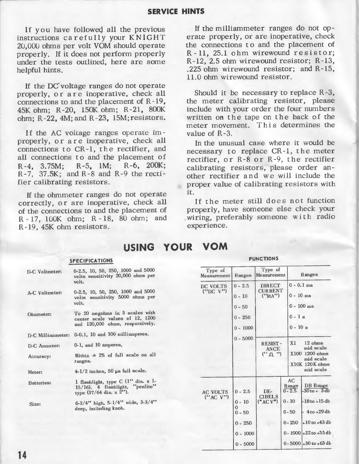
If
the
milliammeter
ranges
do
not
op-
erate
properly,
or
are
inoperative,
check
the
connections
to
and
the
placement
of
R-11,
25.1
ohm
wirewound
resistor;
R-12,
2.5
ohm
wirewound
resistor;
R-13,
.225
ohm
wirewound
resistor;
and
R-15,
11.0
ohm
wirewound
resistor.
Should
it
be
necessary
to
replace
R-3,
the
meter
calibrating
resistor,
please
include
with
your
order
the
four
numbers
written
on
the
tape
on
the
back
of
the
meter
movement.
This
determines
the
value
of
R-3.
In
the
unusual
case
where
it
would
be
necessary
to
replace
CR-1,
the
meter
rectifier,
or
R-8
or
R-9,
the
rectifier
calibrating
resistors,
please
order
an-
other
rectifier
and
we
will
include
the
proper
value
of
calibrating
resistors
with
i.
If
the
meter
still
does
not
function
properly,
have
someone
else
check
your
wiring,
preferably
someone
with
radio
experience.
USING
YOUR
VOM
SPECIFICATIONS
0-2.5,
10,
50,
250,
1000
and
5000
volts
sensitivity
20,000
ohms
per
volt.
D-C
Voltmeter:
A-C
Voltmeter:
0-2.5,
10,
50,
250,
1000
and
5000
volts
sensitivity
5000
ohms
per
volt.
To
20
megohms
in
3
scales
with
center
scale
values
of
12,
1200
and
120,000
ohms,
respectively.
Ohmmeter:
D-C
Milliammeter:
0-0.1,
10
and
100
milliamperes.
D-C
Ammeter:
0-1,
and
10
amperes,
Accuracy:
Within
+
2%
of
full
scale
on
all
ranges.
Meter:
4-1/2
inches,
50
pa
full
scale.
Batteries:
1
flashlight,
type
C
(1”’
dia.
x
I-
15/16).
4
flashlight,
‘“‘penlite’’
type
(37/64
dia.
x
2”’).
Size:
6-3/4’
high,
5-1/4”’
wide,
3-3/4?
deep,
including
knob.
14
FUNCTIONS
Type
of
Ranges
|Measurement
0-
2.5
DIRECT
CURRENT
MA")
Type
of
Measurement
DC
VOLTS
(‘DC
Vv”)
0-
10
0-
10
ma
XI
12
ohms
mid
scale
X100
1200
ohms
mid
scale
XIOK
120K
ohms
RESIST
-
DB
Range
AC
VOLTS
-30to+
3ddb
(“AC
V"’)
0-250
|+10to
+43
db
0-
1000
}+22
to
+55db
0-
5000
|+30
to
+63
db
With
your
KNIGHT
VOM
you
can
perform
a
very
great
variety
of
measurements.
The
different
measure-
ments
are
selected
(a)
by
different
panel
jacks
into
which
the
test
leads
are
inserted
and
(b)
by
the
posi-
tion
of
the
Function
Switch.
A
number
of
scales
on
the
meter
allow
proper
readings
for
any
range
of
any
function
provided.
The
Function
Switch
has
18
posi-
tions
and
2
decks.
This
makes
it
possible
to
connect
the
different
components
of
the
instrument
so
that
d-c
and
a-c
voltages,
direct
and
alternating
currents,
and
resistances
can
be
measured.
The
meter
has
a
highly
sensitive
50-ua
moving
coil
permanent
magnet
move-
ment.
A
calibrating
resistor
(R3)
assures
the
highest
degree
of
accuracy
of
the
dial
indications.
The
meter
serves
as
the
indicator
for
all
measurements.
It
has
separate
scales
for
a-c
voltage,
d-c
voltage,
decibels,
xesistance
and
current.
Preliminary
Adjustments
Before
any
measurements
are
made,
be
sure
the
instrument
is
placed
squarely
on
a
bench
where
the
measurement
is
to
be
performed.
Always
check
that
the
meter
pointer
is
lined
up
with
the
zeros
on
the
left
hand
side.
If
the
pointer
does
not
fall
in
line
with
these
marks,
turn
the
bakelite
screw
directly
above
the
word
“‘OFF”’
either
left
or
right
until
pointer
is
positioned
correctly.
Another
reminder
before
using
the
meter
for
a
par-
ticular
type
of
measurement
is
to
make
certain
that
the
operator
understands
fully
how
to
handle
this
in-
strument,
as
well
as
its
capabilities.
With
this
in
mind,
the
following
paragraphs
are
written,
to
give
an
outline
on
how
to
use
the
KNIGHT
VOM
to
your best
advantage.
How
to
Measure
D-C
Voltoges
Coution:
Wherever
possible,
disconnect
power
from
the
equipment
under
test
before
connecting
the
meter.
In
cases
where
it
is
impossible
to
do
this,
connect
the
leads
separately
and
use
only
one_hand
at
any
one
time.
Grasp
the
test
prod
well
back
from
the
metal
tip
and
make
momentary
contact
with
the
circuit
under
test
by
letting
the
metal
tip
of
the
prod
touch
the
point
at
which
the
potential
exists.
Never
touch
any
part
of
the
equipment
under
test
with
the
other
hand.
Plug
the
black
test
lead
into
the
““COM’’
jack
and
the
red
test
lead
into
the
““V.
,
.A”’
jack.
First
touch
the
probe
end
of
the
black
(negative)
test
lead
to
the
negative
side
of
the
circuit
to
be
checked.
Then,
leaving
one
hand
free,
touch
the
red
(positive)
test
probe
to
the
positive
terminal
of
the
circuit
to
be
tested.
It
is
a
good
practice
always
to
start
with
the
highest
range
available,
as
a
protection
for
your
meter.
Then,
after
first
indication,
the
switch
should
be
reset
to
the
position
in
which
more
accurate
read-
ings
can
be
obtained.
If
possible,
make
final
readings
on
a
range
on
which
the
indication
is
in
the
right
hand
half
of
the
scale,
because
meter
accuracy
is
based
on
full
scale
value.
Turn
the
power
on
and
observe
the
meter
deflec-
tion.
(If
the
pointer
deflects
to
the
left
instead
of
to
the
right,
turn
the
power
off
and
switch
the
connections
of
the
red
and
black
test
leads
around.)
The
value
of
the
measured
voltage
can
now
be
read
from
the
appropriate
meter
scale,
taking
into
account
the
range
setting
of
the
Function
Switch.
Read
on
tne
meter
scale
whose
extreme
right-hand
Rn
marker
is
labeled
with
the
full-scale
value
indicated
by
the
Function
Switch
or
some
multiple
or
submultiple
of
it.
For
d-c
voltage
readings,
use
only
the
black
scales
marked
“*DC’’.
For
the
0-2.5
v
d-c
range
use
the
250
v
d-c
scale.
Divide
meter
scale
reading
by
10.
Each
minor
scale
division
equals
0.05
v
d-c.
For
the
0-10
v
d-c
range
use
the
10
v
d-c
scale.
Read
scale
directly.
Each
minor
scale
division
equals
-2v
d-c.
For
the
0-50
v
d-c
range
use
the
50
v
d-c
scale.
Read
scale
directly.
Each
minor
scale
division
equals
Iv
de.
For
the
0-250
v
d-c
range
use
the
250
v
d-c
scale.
Read
scale
directly.
Each
minor
division
equals
5
v
d-c.
For
the
0-1000
v
d-c
range
use
10
v
d-c
scale.
Multiply
scale
reading
by
100.
Each
minor
scale
division
equals
20
v
d-c.
For
the
0-5000
v
d-c
range
use
50
v
d-c
scale.
Multiply
reading
by
100.
Each
minor
scale
division
equals
100
v
d-c.
If
d-c
voltages
in
excess
of
1000
v
but
less
than
5000
v
are
to
be
measured,
the
red
test
lead
has
to
be
plugged
into
the
‘5000
V
DC’
jack.
If
working
with
high
potentials
of
this
order,
make
doubly
sure
that
the
Caution
paragraph
at
the
beginning
of
this
section
is
strictly
observed.
How
to
Measure
A-C
Voltages
NOTE:
Follow
same
precautions
as
under
“Caution”?
in
above
section
‘‘How
to
Measure
D-C
Voltages.
’’
Plug
the
black
test
lead
into
the
“‘COM’’
jack
and
the
red
test
lead
into
the
“‘V,
.A’’
jack.
Clip
the
probe
of
the
black
test
lead
to
one
terminal
of
the
potential
to
be
measured
and
the
probe
end
of
the
red
test
lead
should
be
touched
to
the
other
terminal
of
the
potential.
Always
start
with
the
highest
“‘AC
V’’
range
available,
as
a
protection
for
your
meter.
Then
after
obtaining
the
first
indication,
reset
the
Function
Switch
to
the
position
in
which
a
convenient
meter
reading,
preferably
in
the
upper
half
of
the
scale,
is
obtained.
Tum
the
power
on
and
observe
the
meter
deflec-
tion.
The
value
of
the
measured
voltage
can
now
be
read
from
the
appropriate
meter
scale
taking
into
account
the
range
setting
as
indicated
by
the
Function
Switch.
For
the
0-2.5
v
ac
range
use
2.5
v
a-c
scale.
Read
scale
directly.
Each
minor
scale
division
equals
0.05
v
ac.
All
other
a-c
voltage
scales
are
chosen
and
read
in
the
same
way
as
the
d-c
scales
discussed
in
the
previous
section,
except
that
the
red
“‘AC’’
scales
are
used.
If
a-c
voltages
in
excess
of
1000
v,
but
not
higher
than
5000
v
a-c
are
to
be
measured,
the
red
test
lead
has
to
be
plugged
into
the
‘5000
V
AC”
jack.
If
working
with
high
potentials
of
this
order,
be
doubly
sure
that
the
Caution
at
beginning
of
previous
section
is
strictly
observed.
19
A-C
voltage
measurements
can
be
made
at
any
frequency
from
25
cps
through
the
audio
range.
At
higher
frequencies,
shunting
capacitance
in
the
rec-
tifier
causes
readings
to
become
increasingly
low.
How
to
Measure
D-C
Resistances
Caution:
Before
making
any
resistance
meas-
ee
.
2 .
urements
in
a
circuit,
make
certain
that
the
power
is
turned
off.
It
is
also
advisable
to
discharge
any
capacitors
in
the
part
of
the
circuits
in
which
resistance
measurements
are
to
be
made.
Turn
the
Function
Switch
to
one
of
the
“‘
1
”
positions.
Plug
the
black
test
lead
into
the
‘‘COM’’
jack
and
the
red
lead
into
the
““V.
©..A’’
jack.
Con-
nect
the
prod
ends
of
these
two
test
leads
together.
Turn
the
‘‘
1.
ADJ’’
knob
until
meter
reads
full
scale
deflection,
at
which
the
pointer
lines
up
with
zero
on
the
ohms
scale.
Turn
Function
Switch
to
such
‘*
(L”’
position
that
the
meter
will
read
somewhere
in,
or
as
near
as
pos-
sible
to,
the
center
portion
of
the
scale
when
the
measurement
is
made.
Recheck
if
the
meter
deflects
full
scale
when
the
two
test
lead
probes
are
connected
together.
Connect
the
test
prods
respectively
to
the
termi-
nals
of
the
resistance
to
be
measured
and
observe
the
meter
reading.
After
any
change
of
ranges,
the
“<0.
ADJ’?
should
be
rechecked.
The
value
of
the
measured
resistance
can
be
determined
by
multiplying
the
ohms
scale
meter
reading
by
the
factor
indicated
by
the
Function
Switch
knob,
The
following
paragraph
shows
the
d-c
resistance
range
covered,
and
the
center-scale
reading
for
each
Function
Switch
setting.
If
the
Function
Switch
is
in
“‘fl
X1”
position,
the
0-1
K
ohm
range
is
covered;
center
scale
reading
is
12
ohms.
Read
scale
directly.
If
the
Function
Switch
is
in
the
“‘{L
X100”
position,
the
100
ohms
-
100
K
ohms
range
is
covered.
Center
scale
reading
is
1200
ohms.
Multiply
scale
yeading
by
100.
I£
the
Function
Switch
is
in
the
“0
X10
K’’
position,
the
10
K
-
10
Meg
range
is
covered.
Center
scale
reading
is
120
K
ohms.
Multiply
scale
reading
by
10,000.
It
always
should
be
kept
in
mind
that
in
the
measurement
of
resistance
a
current
is
made
to
flow
through
the
unknown
resistance.
Usually
this
current
is
so
smal]
that
it
can
be
neglected.
However
on
the
lowest
ohms
range
(X1)
the
halfscale
reading
is
12
ohms.
That
means
a
current
of
65
milliamperes
is
flowing
through
the
unknown
reaistor.
If
lower
re-
sistances
than
12
ohms
are
measured,
the
current
through
them
may
be
as
high
as
130
ma.
Therefore
it
is
good
practice
to
consider
the
current
flow
first
when
measuring
the
d-c
resistance
of
a
device
which
can
safely
pass
only
low
currents
without
burning
out.
For
all
other
cases
no
damage
will
result
as
long
as
the
ohmmeter
current
does
not
exceed
the
current
rating
of
the
unknown
resistance.
How
to
Measure
Direct
Current
Never
connect
the
test
leads
across
any
source
of
voltage
directly
when
the
VOM
is
used
as
a
current
meter,
otherwise
the
meter
will
be
damaged.
Instead,
always
connect
the
meter
in
series
with
the
load.
Plug
the
black
test
lead
into
the
“‘COM”’
jack
and
the
red
lead
into
the
“V.
1.
.A’’
jack.
Tum
the
Function
Switch
to
any
“MA”
or
“A’’
position
appropriate.
It
is
good
practice
to
start
with
highest
range
and
then
reset
switch
to
obtain
a
con-
venient
reading.
16
li
currents
in
the
order
of
1
to
10
amperes
are
to
be
measured,
the
red
lead
has
to
be
plugged
into
the
“10
A”?
jack.
Open
the
circuit
in
which
the
current
is
to
be
measured.
Connect
the
black
test
lead
probe
to
the
negative
side
of
the
circuit
break,
and
the
red
test
lead
probe
to
the
positive
side.
Connect
the
circuit
under
test
to
its
power
source.
The
resulting
meter
deflection
is in
a
direct
proportion
to
the
unknown
current.
To
find
the
magnitude
of
the
current,
the
meter
reading
has
to
be
multiplied
by
the
factor
indicated
by
the
Function
Switch.
The
listing
below
gives
the
different
ranges
covered,
the
scale
on
which
the
meter
reading
is
done,
and
the
multiplication
factor
of
each
current
range.
For
0-0.1
ma
range
use
the
‘‘DC
10”
scale.
Divide
meter
scale
reading
by
100.
Each
minor
scale
division
equals
0.002
ma.
For
0-10
ma
range
use
the
““DC
10”
scale.
Read
meter
scale
directly.
Each
minor
scale
division
equals
0.2
ma.
For
the
0-100
ma
range
use
the
‘DC
10”
scale.
Multiply
meter
scale
reading
by
10.
Each
minor
scale
division
equals
2
ma.
For
the
0-1
a
range
use
the
“‘DC
10’
scale.
Divide
meter
scale
reading
by
10.
Each
minor
scale
division
equals
0.02
a.
For
the
0-10
a
range
use
“‘DC
10”?
scale.
Read
scale
directly.
Each
minor
scale
division
equals
0.2
a.
If
the
meter
pointer
is
deflected
to
the
left
of
the
scale,
the
test
probes
are
connected
in
wrong
polarity.
Turn
off
the
power,
reverse
the
meter
lead
connec-
tions,
and
turn
on
the
power
again.
How
to
Use
the
VOM
as
an
Output
Meter
Sometimes
it
is
necessary
to
measure
an
a-c
voltage
which
is
superimposed
on
a
d-c
voltage.
Correct
measurement
of
the
a-c
component
in
such
a
case
is
possible
by
use
of
the
OUTPUT
circuit
of
the
VOM,
in
which
a
d-c
blocking
capacitor
is
employed
to
keep
direct
current
from
the
meter,
which
then
indicates
only
the
a-c
voltage.
To
measure
voltages
of
this
nature,
plug
the
black
test
lead
into
the
‘‘COM’’
jack
and
the
red
test
lead
into
the
“OUTPUT”
jack.
Then
proceed
as
indicated
under
‘‘How
to
Measure
A-C
Voltages’’.
Since
the
5000
v
a-c
range
would
require
a
change
in
the
red
lead
connection,
the
blocking
capacitor,
necessary
for
output
measurement
would
not
be
connected
in
the
meter
circuit,
therefore
this
a-c
range
can
not
be
used
for
output
measurements,
unless
d-c
is
kept
out
by
an
external
capacitor
or
isolating
transformer.
When
a-c
voltages
are
measured
with
the
output
meter,
the
impedance
of
the
d-c
blocking
capacitor
will
have
an
effect
on
the
accuracy
of
the
meter
reading.
The
error
which
occurs
varies
with
the
frequency
of
the
applied
voltage,
and
becomes
negli-
gible
on
the
50
v
scale
and
higher.
The
actual
voltage
will
then
be
higher
than
the
measured
value.
The
higher
the
frequency
the
smaller
this
error
will
become.
How
to
Measure
Output
Voltages
in
DB
(Decibels)
A-C
output
voltages
are
often
measured
in
units
called
decibels,
which
are
used
to
indicate
power
levels
in
amplifiers
or
general
telephone
work.
The
DB
scale
(bottom
meter
scale)
is
based
on
the
voltage
developed
across
a
500-ohm
line
when
0.006
watts
are
dissipated.
This
voltage
is
a
reference
taken
as
0
db.
Such
a
voltage
deflects
the
pointer
to
1.73
v

ac
on
the
2.5
v
a-c
range.
Therefore,
a
direct
meter
reading
in
terms
of
decibels
can
be
made
only
when
the
meter
is
connected
across
a
500-ohm
resistive
load.
Otherwise
only
relative
db
measurements
can
be
obtained.
However,
in
a
large
number
of
cases
relative
measurements
are
appropriate,
since
reference
conditions
are
defined
by
other
factors
and
only
rela-
tive
variations
are
important.
Frequency
response
to
3-db
“fall-off?
points
is
an
example.
The
following
is
the
procedure
to
obtain
a
db
meter
indication.
Plug
the
red
test
lead
into
the
“OUTPUT”
jack,
to
block
any
d-c
voltage
present
in
circuits
tested.
The
impedance
of
the
capacitor
can
be
disregarded
for
most
applications.
However,
when
no
d-c
voltage
is
present,
the
“V..0..A’’
jack
might
be
used
just
as
well.
Tbe
black
test
lead
is
plugged
into
the
“COM”?
jack.
Rotate
the
range
switch
to
a
high
‘‘AC
V’
range
and
work
down
to
one
which
is
correct
for
the
voltage
to
be
measured.
Connect
the
test
prods
to
the
point
of
the
circuit
where
the
measurement
is
to
be
made.
The
meter
pointer
will
indicate
some
reading
in
db.
If
tbe
measurement
is
made
across
a
500-ohm
impedance,
a
reading
in
absolute
db
(with
respect
to
6
mw)
is
obtained.
The
final
db
indication
is
determined
by
the
value
indicated
on
the
db
meter
scale
plus
the
addition
of
a
constant,
depending
on
the
range
setting.
The
table
at
the
lower
right
corner
of
the
meter
face
will
give
these
constants.
How
to
Measure
Alternating
Current
ge
RE
Ee
The
ac
voltage
ranges
may
also
be
used
to
measure
alternating
current
at
power
line
frequencies
by
simply
inserting
a
known
resistor
(of
low
resistance
and
sufficient
wattage
to
carry
unknown
alternating
current)
and
measuring
the
voltage
across
it.
The
formula:
I
(Amperes)
=
Sega
is
used
to
find
the
alternating
current
flowing
in
this
circuit.
How
to
Measure
Operating
Voltages_in
Electronic
Equipment
Operating
voltages
are
usually
measured
between
a
given
terminal
and
a
reference
point.
Usually
ground
(chassis)
is
this
reference
point.
Reference
voltage
data
appear
in
service
literature
in
several
different
forms.
However,
in
all
cases
the
conditions
for
these
measurements
should
be
observed,
otherwise
measurements
are
not
valid.
When
the
meter
is
connected
in
d-c
circuits,
polarity
should
always
be
observed.
The
black
lead,
connected
to
“‘COM’?
should
always
be
at
the
low
voltage
points.
Incorrect
meter
connection
will
not
produce
a
usable
meter
reading.
Since
d-c
operating
voltage
checks
will
help
to
track
down
circuit
breakdowns,
a
few
examples
of
tube
electrode
voltages,
which
actually
indicate
if
the
circuit
is
functioning
correctly,
will
be
shown.
Cathode
voltages
are
most
often
bias
voltages,
and
indicate
whether
a
tube
is
operating
over
tbe
proper
portion
of
its
characteristic.
Screen
grid
voltage
measurements
can
give
in-
dications
of
the
functioning
of
the
associated
circuits.
Very
low
voltages
at
these
points
may
indicate
a
leaky
bypass
capacitor.
Abnormally
high
voltages
might
mean
a
faulty
dropping
resistor.
Plate
voltage
measurements
can
show
an
open
plate
load
resistor
or
transformer
by
the
complete
absence
of
potential.
Low
plate
voltage
indicates
higher
conduction
than
a
high
plate
potential.
If
tbe
value
of
the
plate
load
resistor
has
a
higher
resistance
than
the
meter
impedance,
the
meter
reading
will
not
read
the
actual
existing
voltage,
but
a
value
which
is
somewhat
lower.
The
suggestions
given
under
“How
to
Measure
D-C
Voltages’’
should
be
followed
in
such
cases,
In
grid
circuits,
the
grid
leak
resistors
have
usually
a
rather
high
resistance.
The
d-c
voltages
are
also
of
low
magnitude
making
it
rather
difficult
to
use
a
fairly
high
d-c
voltage
range
to
maintain
a
high
meter
resistance.
Consequently
the
resulting
readings
are
not
a
very
reliable
indication.
In
clipper,
power
amplifier,
and
oscillator
circuits,
grid
voltage
can
be
measured
with
a
20,000
ohms
per
volt
meter,
with
a
minimum
error
occurring
since
the
grid
leak
resistance
values
are
not
very
high
and
will
not
be
affected
by
the
meter
resistance.
In
oscillators
with
grid
leak
bias,
the
grid
voltage
is
proportional
to
the
amplitude
of
the
oscillations.
Therefore
variations
of
this
voltage
when
tuning
the
oscillator
indicate
unequal
output
at
different
fre-
quencies,
D-C
voltages
in
ave
or
age
circuits
give
important
clues
of
the
operation
of
the
receiver
either
when
the
signal
is
or
is
not
received.
During
alignment
a
specified
voltage
has
to
be
applied
to
such
systems,
which
can
be
checked
by
a
VOM
connected
to
that
line.
Also
overloading,
witb
resulting
stage
blocking,
can
be
checked
by
voltage
measurement
of
the
avec
and
age
systems.
The
d-c
voltmeter
can
also
be
used
as
an
align-
ment
indicator.
For
this
purpose,
connect
the
meter
across
the
plate
load
resistor
of
the
detector
and
set
Function
Switch
until
a
deflection
of
the
meter
pointer
results.
Tben
proceed
with
the
regular
alignment
using
the
meter
as
a
peak
or
dip
indicator.
The
operation
of
a-c
circuits
in
electronic
equip-
ment
can
also
be
checked
by
tracing
the
voltages
applied
to
the
different
circuits.
The
frequency
range
of
the
VOM
permits
only
the
check
of
voltages
up
to
the
low
audio
frequencies.
For
example,
transformers
in
power
supplies
may
be
checked
by
connecting
the
meter
across
the
dif
ferent
windings
and
comparing
the
measured
voltages
to
those
given
as
references,
17
*WOA
LHOIN»
‘WVUOVIC
DILVWAHDS
°S
JUNSIA
(4
Ove)
(2
own)
(Q
yor)
(2
Ove)
(@
xOWl)
(v
Ove)
indino
NOWAWOD
V-U-A
SdWV
Ol
ov
AOO0OS
od
AO0O0OS
©
©)
©
©
2-u
iru
one's
93W
02
94W
09
ALNQHS
OZe
*
e-y
NOE
KS
‘)
aunsia
‘osTv
33S
SWHO
000‘000'!
2
93W
(WY¥SVIO
NG
ss
Nid
ONIND07
(%)
sysINais¥
SWHO
000't=
»
Him
SU3EHNN
48
Q3LVOIGNI)
STWNINM
SL
LNIOd
JIL
SWHO
NI
Q31LVSIONI
SYOLSISSY
T1V
Sb
NOLLVUSITVS
e-8
oz
e-8
7.
nie
|
ome
|
046
Oo
Yor
ov
l
of
|
Iz]
aay
ee
*
b
329
|
¢2-¥
a
aose
|
|
93
SI
od
|
re
t]+
A000S
|
|
6i-u
ro
yOLSIS3Y
|
|
|
|
Sa
a
ad
43)
411034
ee)
bt
O
aaa
rep
eres
oe
as
oo
7
292
O J
YOLSISAY
ve
¥el
NOLLVHEITVO
u31aW
e
U
€-¥
18

SYMBOL
NO
DESCRIPTION
PART
NO.
C-1
Capacitor,
paper,
.1
MFD
600V
247014
Note:
When
ordering
resistors
give
com-
plete
description
and
part
number,
R-1
Resistor,
60
megohm,
+
1%
precision
a
366005
R-2
Resistor,
20
megohm,
+
1%
precision
¥
362005
R-3
Resistor,
meter
calibrating
(packed
with
the
meter)
R-4
Resistor,
3.75
megohm,
+
1%
precision
343754
R-5
Resistor,
1
megohm,
+
1%
precision
-
341004
R-6
Resistor,
200K
ohm,
+
1%
precision
342003
R-7
Resistor,
37.5K
ohm,
+
1%
precision
ina
343752
R-8
Resistor,
rectifier
calibrating
(smaller
value)
R-9
Resistor,
rectifier
calibrating
(larger
value)
R-10
Resistor,
SK
ohm,
+
1%
precision
345001
R-11
Shunt,
wirewound
on
blue
form,
25.1
ohm,
+
1%
412517
R-12
Shunt,
wirewound
on
yellow
form,
2.5
ohm,
+
1%
410257
R-13
Shunt,
wirewound
on
red
form,
.225
ohm,
+
1%
412259
R-14
Resistor,
1150
ohm,
+
1%
precision
7
341151
R-15
Shunt,
wirewound
on
green
form,
11.0
ohm,
+
1%
410110
R-16
Resistor,
18K
ohm,
+
1%
precision
a
341802
R-17
Resistor,
100K
ohm,
+
1%
precision
a
341003
R-18
Resistor,
80
ohm,
+
1%
precision
—
340800
R-19
Resistor,
45K
ohm,
+
1%
precision
=
344502
R-20
Resistor,
150K
ohm,
+
1%
precision
—
341503
R-21
Resistor,
800K
ohm,
+
1%
precision
_
348003
R-22
Resistor,
4
megohm,
+
1%
precision
mg
344004
R-23
Resistor,
15
megohm,
+
1%
precision
351505
R-24
Potentiometer,
OHMS
ADJUST,
30K
ohm
390116
R-25
Shunt,
10
ampere,
4.3’
#14
Advance
Wire,
.025
ohm
334001
CR-1
Rectifier,
copper
oxide
621002
M-1
Meter,
50microampere
move-
ment
mountedinfront
panel
040002
SYMBOL
NO.
DESCRIPTION
PART
NO.
S-1
Switch,
FUNCTION,
2-deck
18-position
rotary
432302
B-1
Battery,
1.5
V
‘‘C’”’
450011
B-2,
3,4,5
Battery,
1.5
V
penlite
450013
Quantity
Description
Part
No.
1
ea.
Board,
battery
clip
534005
lea,
Case
701004
2
ea.
End
leads
for
R-25
470022
1
ea,
Handle
920005
6
ea.
Inserts,
jack
532006
1
ea,
Knob,
large
761301
1
ea.
Knob,
small
761001
1
ea.
Label,
paper,
showing
polarity
of
batteries
and
meter
750040
1
ea,
Manual
750041
4
ea.
Nuts,
4-36
hex
570230
2
ea.
Nuts,
10-32
hex
570540
3
ea.
Nuts,
3/8’’
hex
570840
6
ea.
Screws,
4-36
x
3/4’’
BH
560237
2
ea.
Screws,
4-36
x
3/8’’
BH
560234
24’
Solder,
rosin
core
930001
2
ea.
Spacer,
1/8”’
940002
6”
Spaghetti,
small
812001
4"
Spaghetti,
large
812003
1
ea.
Strap,
battery
retaining
470050
2
ea.
Stud,
handle
470025
1
set
Test
leads
(red
&
black)
040001
2
ea.
Washer,
lock,
#10
582500
1
ea,
Washer,
lock,
3/8"’
582700
1
ea,
Wire,
#20
bare,
9’’
length
806000
5
ea.
Wire,
red,
2’’
length
801002
3
ea.
Wire,
orange,
3’’
length
801003
1
ea.
Wire,
yellow,
4’’
length
801004
2
ea,
Wire,
green,
5’’
length
801005
lea.
Wire,
blue,
6’’
length
801006
1
ea.
Wire,
violet,
7’’
length
801007
1
ea.
Wire,
white,
9’’
length
801009
TOOLS
YOU
MAY
NEED
Stock
No.
Description
Price*
46N852
Soldering
pencil
$4.73
46N449
Long-nose
pliers
1.76
46N431
Diagonal
cutting
pliers
1.55
45N796_
6°’
screwdriver
72
43N831
Set-screwdriver
.27
*All
Prices
subject
to
change
without
notice.
19
Table of contents
Other Allied Radio Recording Equipment manuals


