Allied Radio KNIGHT 96-144 User manual

PnoToFACT* FolJ"t KNIGHT
riloDEtS 96-144, 96-499
Or
o
T
I
o\
;- -.\
rrI
+*
e+
3t
ln
J
EI
o
o
==
o
E'
llt
F
UI
ri
iE
.5i
€
I
5
€
I
F'igure 1
GENERAL INFORMATICN
rhe Knight Models g6-144and g6-4gg Tape Recorders are designed to
magnetically record on a 5" or ?" reel of l/4, ' wide tape, two tracks
instead of one which doubles the playing time with no loss in frequency
response or quality. 'rhese models 96-144 and g6-4gg Recorders are
identical except f or the speed. Model 96-144 is 7-l/2,' per second
while the Model 96-4gg is g-B/4" per second.
Model 96-144 '7-t/2" per second - ?" reel - l/z hour playing time
one track, or t hour playing time - two track operation
Model 96-499 - 3-B/4" per second - ?" reel - t hour playing time one
track or, 2 hours playing time - two track operation.
These Recorders incorporate two Inputs - Radio and Microphone, two
outputs - Ext. Amplifier and Ext. speaker, Fast Forward and Fast Re-
wind. The Knight Recorders may also be used as a p.A. system.
Allied Radio C orporation
83.? West Jackson Boulevard, Chicago ?, Illinois
TOHE
YOLUME
c0l{TR0t
fhis msteriol compiled ond published by
sAtls & co., lNc., lNDlANApOllS, INDIANA
COPYRIGHT l95a . ALL RIGHTS RESERVED
DATE I - 52 $rT t58 TOTDER 6
HOWAR,D l/.
*\...-ar
*;ji
't:
*
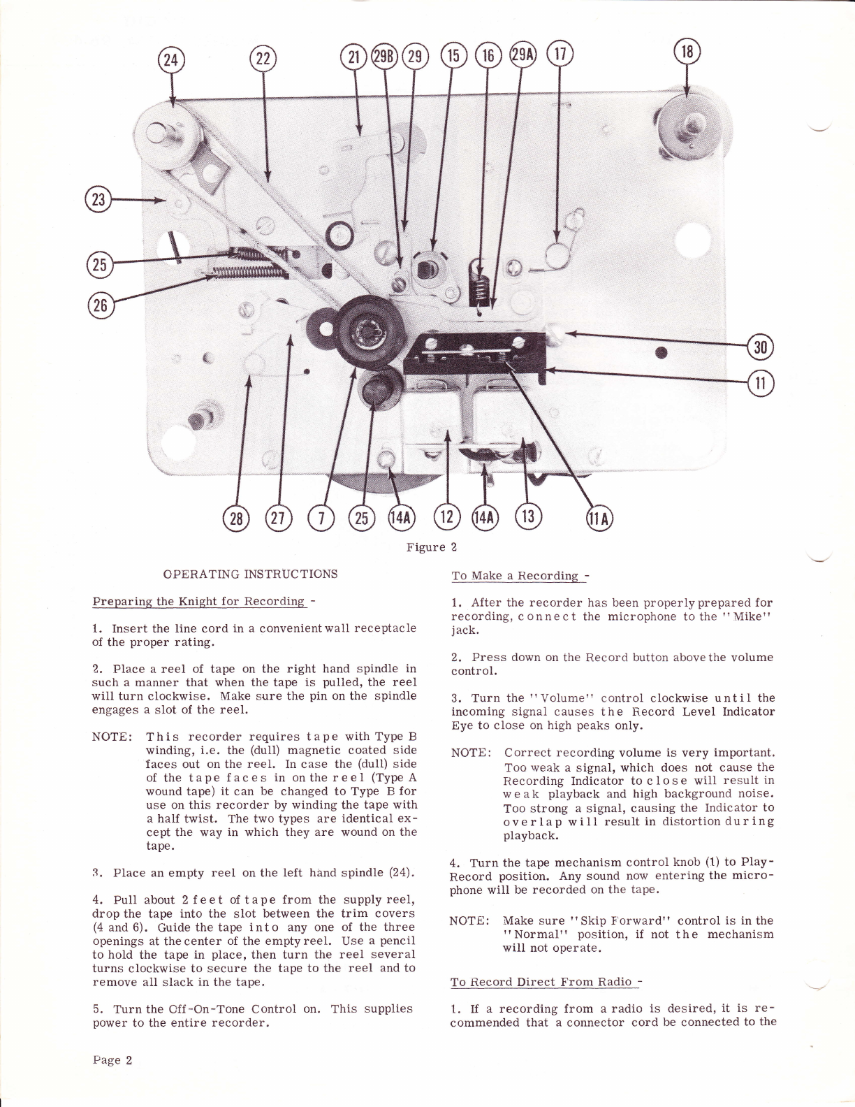
Figure 2
CPERATING INS TRUC TIONS
trreparing the Knight for Recording -
1. Insert the Iine cord in a convenientwall receptacle
of the proper rating.
2. Place a reel of tape on the right hand spindie in
such a manner that when the tape is pulled, the reel
will turn clockwise. Make sure the pin on the spindle
engages a slot of the reel.
NOTE: This recorder requires tape with Type B
winding, i.e. the (dull) magnetic coated side
faces out on the reel. In case the (dull) side
of the tape f aces in onthereel (TypeA
wound tape) it can be changed to Type E for
use on this recorder by winding the tape with
a half twist. The two types are identical ex-
cept the way in which they are wound on the
tape.
3-. Place an empty reel on the left hand spindle (2a).
4. trull about 2 f.e et of tape from the supply reel,
drop the tape into the slot between the trim covers
(4 and 6). Guide the tape into any one of the three
openings at the center of the empty reel. Use a pencil
to hold the tape in place, then turn the reei several
turns clockwise to secure the tape to the reel and to
remove all slack in the tape.
5. Turn the Cff -On-Tone Control on. This supplies
power to the entire recorder.
Page 2
To Make a Recording -
1. After the recorder has been properlyprepared for
recording, connect the microphone to the ?'Mike?'
jack.
2. Press down on the Record button above the volume
control.
3. Turn the 'r Volume " control clockwise u n t i I the
incoming signal causes the F-ecord Level Indicator
Eye to close on high peaks only.
NOTE: Correct recording volume is very important.
Too weak a signal, which does not cause the
Recording Indicator to close will result in
weak playback and high background noise.
Too strong a signal, causing the Indicator to
ove rlap will result in distortion dur ing
playback.
4. Turn the tape mechanism control knob (1) to PIay-
Record position. Any sound now entering the micro-
phone will be recorded on the tape.
NOTE: Make sure " Skip F'orward" control is in the
"Normal" position, if not the mechanism
will not operate.
To fi.ecord Direct From Radio -
t. If a recording from a radio is
commended that a connector cord desired, it is re-
be connected to the

,*t
,;:r ii
,! /"4
6il ,'j td
*\'t \i ,:"
irffi -','. Jf
\' r4ffi*.
{":
.... l
'l, l:i' :ttl%
""8 r ffi'
* *'*
T
t
I
J
fta)
3
o
E,
trt
F
UI
r2
IE
.s=
€
o
i
I
€
q.
./
-J"
uv
Figure 3
speaker voice coil of the radio, by means of alligator
clips, and the other end (using a standard phono plug)
of the cord plugged into the " Fadio" Input.
2. Better quality recording from a radio set can be
obtained by connecting to the output of the second de -
tector (usually right across the volume control of the
radio set). This kind of connection may be desirable
in some cases, because any circuit deficiencies in the
amplifier of the radio will not be included in the re-
cording.
To Record From Record Pla er-
1. Connect the output leads of the crystal pickup to
the Radio Input jack through the connecting cable.
2. If the player has a. magnetic cartridge connect to
the output of the preamplifier.
To Stop the Recorder -
The recorder may be stopped at any time by turning
the mechanism control (1) to 'r Offrt. This stops the
movement of the tape and removes the power to the
motor.
Two Track Recording -
1. The Knight is designed for two channel recordings,
therefore, after a reel of tape has been recorded a
second track may be recorded on the same reel, which
doubles the playing time with no Ioss of frequency
response or quality.
NOTE: Recordings are made on l/2 the tape width at
a time; thereby, resulting in two channel re-
cording.
2, This two channel operation is accomplished by re-
moving the reels f rom the recor{er, turning them
over, then placing the f ulI reel of tape on the Feed
Reel spindle (18) and the empty reel on the Take Up
spindle (24).
3. Thread the tape and proceed with the recording in
the same manner as previously described.
4. After this track has been recorded the first track
of recording is ready to be played without rewinding.
5. To Play the first track of recording piace the full
reel on the Feed li,eel spindle and the empty reel on
the Take Up spindle. Thread the tape making sure
the (duII) side of the tape faces the heads, then set
the control as described under "To Play a R,ecording" .
'Io Rewind The Ta
t. To rewind a portion of the tape, or an entire
channel of recording for playback, the tape must be
rewound to the starting point of the recording.
2. First make sure the recording light just above the
Tone control is out. If not, depress the record button
above the Volume control.
3. Turn the mechanism control (1) to " Rewind'r .
Page 3

tt,f
To Plav a Recordi
1. Make sure the tape is threaded properly.
2. Be sure the record light over the Tone control is
out.
3. 'Iurn the mechanism control (1) to trIay-iiecord
position.
4. Set the volume and tone controls at desired levels.
Fast f'orward -
The control marked " Skip Forward-Neutral-Normal"
on the left side of the upper control panel enables you
to skip forward at high speed to any desired section of
the tape. This control is to be used only when the tape
is moving forward in the plav position. 'Iurn the con-
trol to the lef t through the "Neutral" position and
into the "Skip Forward" position holding it there
until the desired place on the ta-pe is reached. Then
release the control by allowing it to spring back into
'rNeutral". Then, move the control backinto
tt Normaltt.
To Plav a Recording Through
an External Amplifier -
1.. Frepare a shielded c able with the proper plugs,
connecting one end of the cable to the Amplifier Cut-
put of the recorder and the othe4 end to the " phono"
.t-age 4
ti
;.ii; iii
ry-:::
input of any good radio set, or high-fidelity record
player amplifier.
To PIav a Recording Through
an External Speaker -
1. Any external FM speaker having a3.2 ohm voice
coil may be plugged into the External Speaker jack
output. vVhen an external speaker is plugged in, the
internal speaker is automatically disconnected.
Using the Knight Recorder as a tr.A. Svstem -
1. Plug the microphone into the Radio jack.
2. Be sure the recording light above the tone control
is out.
3. Keep the microphone as far as possible from the
unit to avoid feed back or 'rhowl'r and adjust the tone
and volume controls to your requirements.
ADJUSTMENTS
Motor Power Switch - (See I'igure 4) -
1. The Off -On-Tone control when turned on supplies
power to t h e entire mechanism, however, the motor
will not run until the mechanism control knob (1) is
turned to either Record-PIay or Rewind trosition,
causing the switch (51) to make contact. Therefore
the switch contacts should be open when the mechan-
ism is in " Stop" position.
;i::::-T,i:
if\
&d
l"
I
Figure 4

To adjust the motor switch, turn the mechanism con-
trol to the " Stop" position. Loosen the two screws
(54A) and adjust the srvitch to the center of the bake-
lite pin on the motor swing plate (51). Continue to
move the switch until there is approximately 1/16'r
gap between the contacts. Tighten the screws (54A).
The Forward Stop Lug - (See Figure 4) -
The forward Stop lug (52) should be set so the motor
swing plate assembly (51) comes to a rest position
against it as soon as the motor pulley (5?) makes firm
contact with the flywheel (40). Excessive pressure
against the flywheelwillprevent the motorfrom start-
ing when the control lever is turned to the " Play-
Recordir position. Insufficient pressure will result
in slippage causing rr i!'owtt. The best setting is to
adjust the forward Stop lug (52) l/16,, from the edge
of the swing plate (51) at the point when the drive
roller begins to touch the flywheel.
There is no motor plate stop adjustment in the ttRe-
wind" position; however, the rewind drive pulley (3?)
is located in a hanger whose position is adjusted by
bending the Stop lug (3?A), see Figure 3, against the
swing plate pushing in a manner that will allow a
clearance between the drive roller (5?) and the re-
wind pulley (3?) in the "Stop" position. This will
also allow the drive roller to engage the drive pulley
in the'rRewind" position. In this position, the re-
wind drive pulley hanger lug (3?A) is moved away
from the stop. The rewind drive pulley (3?) is firmly
held against the motor drive pulley (5?) by the torsion
spring (39) that needs no adjustment.
Pressure Lever and Arm Adjusting Plate -
Set the pressure lever (15), see Figure 2, so that it
is perpendicular to the pressure arm (29A) when the
control knobis in the Record-Playback position. Also
adjust the arm adjusting plate (298) so it will clear
the pressure arm (29A) bV l/64,, ,yhen in this
position.
Detent Lever (38) - (See Exploded View) -
The roller of the detent lever (38) should be adjusted
so that it will engage the detent lever (16) at point X,
as shown in the exploded view, when the controt is in
the " Off" position.
Motor Transfer Lever (41) -
'f he motor transfer lever (41) shoul.d be adjusted
when the control is in the t'Off,' position. To adjust
the transfer lever (41) loosen its set screws and move
the motor plate (51) until the motor drive pulley (5?)
is midway between the rewind drive pulley (37) and
the flywheel (40), then tighten the scrervs.
Head Fressure -
The head pressure is adjusted by means of the two
screws (14A) in the slotted holes in the head bracket
(14). See Figure 2. To make the adjustment, turn the
control knob (1) to'rRecord-Playtr position. Loosen
the screws (14A) then adjust the head into the tape
guide block {11) until the pressure pads (11A) show a
movement of slightly less than l/32,, on the reverse
side of the tape guide (11).
-
Head Alignment -
The lateral movement of each head is done by moving
the heads in the required direction by means of the
screws in the slotted holes that hold the heads to the
head bracket (14). The position should be such that
there is no hanging up of the tape pressure guide when
the control lever is turned to the " Off" position.
Make sure after the heads are adjusted that they are
parallel with the tape as it is pulled past the heads.
TROUBLES
Irregular Speed'rWowrt -
1. Felt pressure pads (11A) in tape guide assembly
(1 1) worn.
(a) Replace with new pads.
2. Oilor greaseon drive roller (5?), flywheel assem-
bly (40), or pressure roller (?).
(a) Clean with alcohol.
3. Head pressure too great (see adjustment on
I'Head Pressurer'). Be careful not to disturbthe
head alignment.
4. Check pressure roller lever (1b) to see if it is
perpendicular to the pressure arm (2gA). When in the
" Record-Flay'' position. See Adjustments on 'r pre-
ssure Lever and Arm Adjusting plate".
5. Drive roller (5?) or pressure roller (?) eccentric.
Allow mechanism to run for 20 minutes. ff after this
time the rollers are still eccentric, replace with new
rollers.
6. Motor shaft binding. Motor shaft should turn free-
ly when the control knob is in the " Off[ position. If
necessary, realign bearings by tapping motor lighily
with a wooden mallet.
?. Detent spring (26) not properly connected. See
Figure 2. If spring (26) is not connected, the detent
slide (36) will not be held against the detent lever (38)
resulting in the motor drive pulley (5?) not being held
in firm contact with the capstan.
Motor Runs but Mechanism Will Not Operate -
1. Motor transfer lever (41) not adjusted properly.
See Adjustments on " Motor Transfer Lever", and
" The Forward Stop Lug".
2. Drive roller (57) defective.
3. Fast f'orward control in 'r Neutralt' position.
(a) Turn contr.ol to tr Normalr' .
Mechanism Runs Forward But Will Not Rewind -
t. Checkdrive belt (35) for treing broken or loose.
Replace.
2. Motor transfer lever (41) not adjusted properly.
See adjustment on " Motor Transfer Lever (41)" .
Mechanism Rewinds But WiIl Not Run Forward -
1. Forward stop lug (52) out of adjustment. See Ad-
justment on rr Forward Stop Lug".
=o
(,
|lt
F
ta
s2
i0
.Ai
€
T
I
€
€
Page 5
This manual suits for next models
1
Other Allied Radio Recording Equipment manuals


