Allied Vision Alvium User manual

Page 1 of 18
APPLICATION NOTE
Preparing Cameras without Sensor Cover Glass
Alvium, Manta, Prosilica GT V3.0.1
2022-Sep-27
1. Terms used in this document
2. Scope
RCG and TCG cameras must be handled with utmost care to avoid damage to the image sensor. Follow the
instructions in this document to properly prepare RCG or TCG cameras for operation.
3. Safety notes
3.1. Electrostatic discharge (ESD)
Electrostatic charge builds up in the body when walking on carpeted floor. This can discharge when
touching metal objects like a door handle. Such ESD can damage electronic devices, especially when tools
or hands get in contact with connectors. We recommend measures to avoid damage by ESD:
• Unpacking: Remove the camera from its anti-static packaging only when your body is grounded.
• Workplace: Use a static-safe workplace with static-dissipative mat and air ionization.
• Wrist strap: Wear a static-dissipative wrist strap to ground your body.
• Clothing: Wear ESD-protective clothing. Keep components away from your body and clothing. Even if
you are wearing a wrist strap, your body is grounded but your clothes are not.
3.2. Sensor damage
Follow the instructions thoroughly to avoid damage to sensor and camera. Work in a dust-free environment
(class 100 or better) with humidity according to ESD requirements.
Term Description
Circular protection foil Adhesive tape to protect the lens mount against dirt
Cover glass Glass layer on top of the sensor surface, removed for RCG and TCG cameras
lbf-in Inch-Pounds, unit for maximum torque, based on the British imperial units system
(1 lbf-in = 0.113 Nm)
Nm Newton meter, unit for maximum torque; based on the metrical system (1 Nm = 8.85 lbf-in)
PCB Printed circuit board
PCBA Printed circuit board assembly as a set of multiple PCBs
Extended Format housing Extended-sized housing, such as for Prosilica GT1910, GT1660, and GT2300
Large Format housing Large-sized housing, such as for Prosilica GT4905, GT4907, and GT6600
Protection glass Clear “filter” in the camera mount assembly
RCG Removed Cover Glass sensor option
TCG Taped Cover Glass sensor option

Preparing Cameras without
Sensor Cover Glass
Page 2 of 18
4. Warranty conditions
Allied Vision warranty does not cover any damage to the sensor as soon as the cover glass or the circular
protection foil is removed. TCG and RCG cameras have the standard warranty on the electronics, but
excluding sensor:
5. Common instructions
5.1. Unpacking cameras
1. Open the shipping box.
2. Take out the ESD bag with the camera.
3. Take the camera out of the ESD bag.
5.2. Checking the camera function
With this simple test, you can check that the sensor of your new Allied Vision camera is working properly.
No lens is required.
1. Connect the camera to a PC.
2. Start Vimba Viewer or another Viewer application to acquire an image.
3. Wave your hand in front of the sensor.
The viewer shows a camera image of a moving shadow. This proves proper camera function.
4. Continue with the corresponding instructions:
•6. Instructions for housed Alvium cameras – RCG on page 3
•7. Instructions for Alvium bare board cameras – TCG on page 4
•8. Instructions for Manta cameras – RCG on page 7
•9. Instructions for Prosilica GT cameras – TCG on page 8.
Camera series Alvium housed cameras Alvium bare board cameras Manta Prosilica
Electronics warranty 3 years 2 years 3 years 3 years
Table 1: Warranty duration by camera series
Warranty conditions
For the warranty of cameras and sensors, see
www.alliedvision.com/en/support/warranty.
NOTICE
Damage to the camera electronics and sensor
• Work in a dust-free environment (class 100 or better) with humidity according
to ESD requirements.
• Observe notes for 3.1. Electrostatic discharge (ESD) on page 1.
• Follow the instructions thoroughly.
Keep camera packaging
• To store the camera
• To ship the camera back in case of damage.
i

Preparing Cameras without
Sensor Cover Glass
Page 3 of 18
6. Instructions for housed Alvium cameras – RCG
At delivery, sensors of RCG cameras are protected by the circular protection foil placed on the lens mount.
This section instructs on removing the circular protection foil and mounting the lens.
1. With your finger tips, starting from the edge, slowly pull the circular protection foil from the lens mount
until removed completely.
2. Mount your optics according to the manual of the lens manufacturer and the Alvium user guide.
Without compensation, cameras could be focused to infinity after the sensor cover glass has been
removed. Therefore, Alvium RCG cameras are calibrated for proper focus before shipping.
NOTICE
Damage to the camera electronics and sensor
• Work in a dust-free environment (class 100 or better) with humidity according
to ESD requirements.
• Observe notes for 3.1. Electrostatic discharge (ESD) on page 1.
• Follow the instructions thoroughly.
Figure 1: Pulling the circular protection foil off the lens mount
NOTICE
Damage to the sensor
If you want to use your camera without lens, observe 3. Safety notes on page 1.
NOTICE
Damage to sensor and lens
If the lens exceeds maximum protrusion, camera or lens may be damaged.
• To avoid damaging the sensor or the back lens, use lenses with a maximum
protrusion within camera specifications. For details, see your camera’s user
guide.
Foil egde
Lens mount
Adhesive
ƉƌŽƚĞĐƟŽŶĨŽŝů
Preparing Cameras without
Sensor Cover Glass
Page 4 of 18
7. Instructions for Alvium bare board cameras – TCG
At delivery, sensors of TCG cameras are protected by the cover glass fixed by adhesive tapes. This section
instructs on removing these tapes and the cover glass. Note that you must mount bare board cameras into
housings immediately after the TCG has been removed.
NOTICE
Damage to the camera electronics and sensor
• Work in a dust-free environment (class 100 or better) with humidity according
to ESD requirements.
• Observe notes for 3.1. Electrostatic discharge (ESD) on page 1.
• To protect the sensor from dirt, mount the camera into a housing immediately.
• Follow the instructions thoroughly.
NOTICE
Damage to sensor and lens
If the lens exceeds maximum protrusion, camera or lens may be damaged.
• To avoid damaging the sensor or the back lens, use lenses with a maximum
protrusion within camera specifications. For details, see your camera’s user
guide.
About the following instructions
The instructions consist of multiple steps. We recommend you to read the
instructions first to get an orientation on camera preparation.
Ease handling
• Use a magnifying glass for better view.
• Read the instructions thoroughly and keep tools at hand for camera
preparation.
Required tools
Before you can remove the TCG, please obtain the required tools shown below.
Required tools Tools short names Purpose
Base magnifier or microscope Magnifying glass For better view
Wooden spatula Spatula To keep the cover glass in position until removed
Precision screwdriver Screwdriver To lift up the adhesive tapes
Pinch nose pliers Pliers To pull off the adhesive tapes
Circular protection foil
(optional)
Circular protection foil To protect the sensor during camera storage
before final hardware installation
Table 2: Required tools to remove a TCG

Preparing Cameras without
Sensor Cover Glass
Page 5 of 18
1. Place the camera on your work bench, with the sensor side facing up.
2. Place the magnifying glass above the camera, with sufficient space to access the TCG and the adhesive
tapes with tools.
3. Take the spatula with one hand.
4. With the spatula, push the cover glass down to keep the sensor protected.
Keep pushing down with the spatula until step 15.
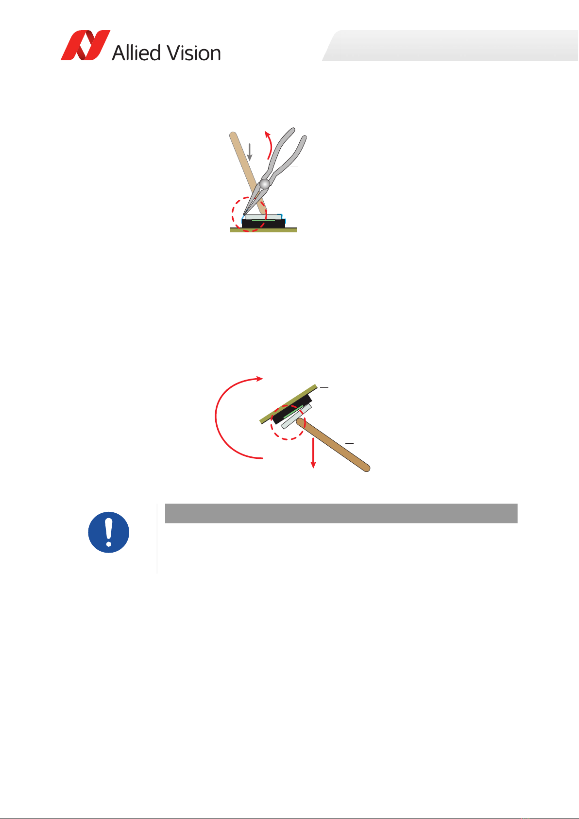
5. Take the screwdriver with the other hand.
6. On the left side of the sensor, carefully push the tool tip of the screwdriver against the corner of the
adhesive tape until it starts to come off. Continue lifting up the corner, until pliers can get a grip.
7. Put the screwdriver aside and take the pliers.
8. Keep pushing down with the spatula until step 15.
Figure 2: Sensor with TCG (schematic view)
Figure 3: Spatula pushing down the cover glass (schematic view)
Figure 4: Screwdriver lifting up the adhesive tape (schematic view)
Sensor
Tape
Bare pixel surface
Glass
Tape
Cover glassAdhesive tape
Spatula
Screwdriver
Preparing Cameras without
Sensor Cover Glass
Page 6 of 18
9. With the pliers, grip the detached corner of tape and slowly pull it off the cover glass and off the sensor
baseplate.
10. Strip off the tape from the pliers.
11. Put the pliers aside.
12. Repeat steps 5. to 11., until all adhesive tapes have been removed from the sensor.
13. With one hand pushing the spatula against the cover glass, take the camera into the other hand.
14. Rotate the camera with the sensor facing down.
15. Slowly release the spatula from the cover glass until it disengages from the camera.
Figure 5: Pliers pulling the adhesive tape off the sensor (schematic view)
Figure 6: Rotating the camera to drop the cover glass (schematic view)
NOTICE
Damage to the sensor
If dirt penetrates the sensor surface, the sensor can be damaged.
• To protect the sensor from dirt, mount the camera into a housing immediately.
Pliers
Spatula
Camera
2
1

Preparing Cameras without
Sensor Cover Glass
Page 7 of 18
8. Instructions for Manta cameras – RCG
At delivery, sensors of RCG cameras are protected by the circular protection foil placed on the lens mount.
This section instructs on removing the circular protection foil and mounting the lens.
1. With your finger tips, starting from the edge, slowly pull the circular protection foil from the lens mount
until removed completely.
2. Mount your optics according to the manual of the lens manufacturer and the Manta User Guide.
Without compensation, cameras could be focused to infinity after the sensor cover glass has been
removed. Therefore, Manta RCG cameras are calibrated for proper focus before shipping.
NOTICE
Damage to the camera electronics and sensor
• Work in a dust-free environment (class 100 or better) with humidity according
to ESD requirements.
• Observe notes for 3.1. Electrostatic discharge (ESD) on page 1.
• Follow the instructions thoroughly.
Figure 7: Pulling the circular protection foil off the lens mount
NOTICE
Damage to the sensor
If you want to use your camera without lens, observe 3. Safety notes on page 1.
NOTICE
Damage to sensor and lens
If the lens exceeds maximum protrusion, camera or lens may be damaged.
• To avoid damaging the sensor or the back lens, use lenses with a maximum
protrusion within camera specifications. For details, see your camera’s user
guide.
Foil egde
Lens mount
Adhesive
ƉƌŽƚĞĐƟŽŶĨŽŝů

Preparing Cameras without
Sensor Cover Glass
Page 8 of 18
9. Instructions for Prosilica GT cameras – TCG
At delivery, sensors of TCG cameras are protected by the cover glass fixed by adhesive tapes. This section
instructs on removing these tapes and the cover glass, starting to disassemble the camera in order to get
access to the sensor.
For Prosilica GT Extended Format housing cameras, start with 9.1. Disassembling Prosilica GT Extended
Format housing cameras on page 8.
For Prosilica GT Large Format housing cameras, start with 9.2. Disassembling Prosilica GT Large Format
housing cameras on page 10.
9.1. Disassembling Prosilica GT Extended Format housing cameras
1. Power off and unplug the camera.
2. With a water resistant ink pen, draw a line (a) across the joint between front assembly and body
assembly. This will serve as an index to reassemble the camera in correct orientation.
3. Loosen and remove the four M2 x 8 socket head cap screws of the front assembly.
4. Detach the front assembly (b) from the body assembly (c).
NOTICE
Damage to the camera electronics and sensor
• Work in a dust-free environment (class 100 or better) with humidity according
to ESD requirements.
• Observe notes for 3.1. Electrostatic discharge (ESD) on page 1.
• Follow the instructions thoroughly.
About the following instructions
The instructions consist of multiple steps. We recommend you to read the
instructions first to get an orientation on camera preparation.
Figure 8: Removing the four M2 x 8 socket head cap screws of the front assembly
Figure 9: Detaching the front assembly
a
b
c

Preparing Cameras without
Sensor Cover Glass
Page 9 of 18
The front assembly consists of the sensor unit (d) and the lens mount (e). The sensor unit must be kept
in one piece to avoid damage to the sensor.
5. With a water resistant ink pen, draw a line (f) across the joint between sensor unit and front assembly.
6. Loosen the two M2 x 16 socket head cap screws (g) of the sensor unit, keeping screws in place.
7. Keeping screws (h) in place, remove the sensor unit (i) from the lens mount (k).
• Continue with 9.3. Removing the taped cover glass on page 12.
Figure 10: Front assembly overview: sensor unit and lens mount
NOTICE
Damage to the sensor
If you must reassemble the sensor unit, do not put the sensor surface down facing
the PCB, as it can damage the sensor.
• Keep the sensor unit in one piece.
• If PCBs have been separated, place the sensor PCB on top with the sensor
surface facing the lens mount.
Figure 11: Loosening the two M2 x 16 socket head cap screws
Figure 12: Removing the sensor unit from the lens mount
de
gg
f
i
h
k

Preparing Cameras without
Sensor Cover Glass
Page 10 of 18
9.2. Disassembling Prosilica GT Large Format housing cameras
1. Power off and unplug the camera.
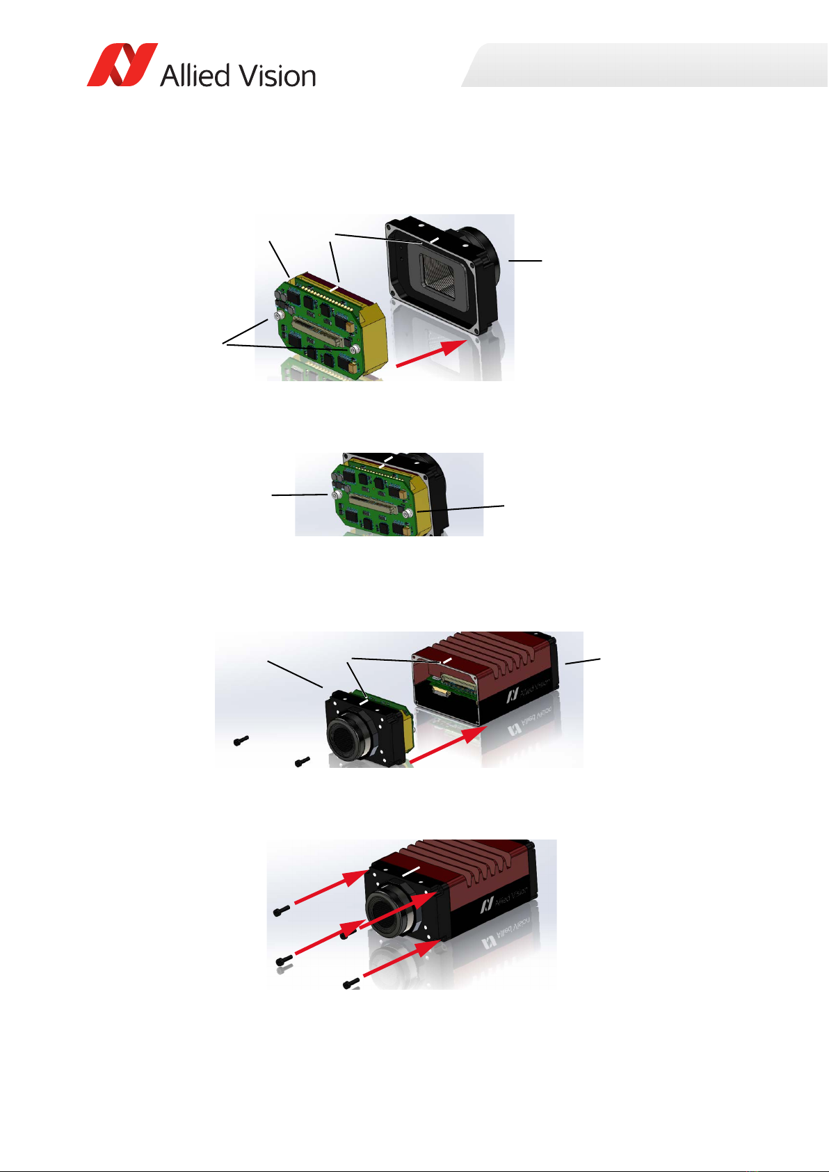
2. Loosen and remove the four M2 x 10 socket head cap screws of the front assembly.
3. Flip the front assembly (c) by approximately 45° to the right side of the body assembly (d).
For the next steps, avoid mechanical stress to the ribbon cable (a).
The ribbon cable is included only for cameras with certain mount options.
4. Disengage the flexible contact bar (b).
5. Continue to flip open the front assembly to an angle of 180° and position the sections next to each
other on the workbench
Figure 13: Removing the four M2 x 10 socket head cap screws of the front assembly
Figure 14: Flipping front assembly away from the body assembly
Continuing the disassembly
• Keep the camera flipped open as described in step 5.
• The illustrations of the next action steps are schematics.
Camera top
a
b
d
c
Lens mount

Preparing Cameras without
Sensor Cover Glass
Page 11 of 18
The front assembly consists of the sensor unit (e) and the lens mount (f).
6. Remove the two M2 x 10 socket head cap screws (g) and spacers from the sensor unit.
7. With a water resistant ink pen, draw a line (i) across the center top of sensor unit and front assembly.
8. Remove the sensor unit (h) from the lens mount (k).
Continuing the disassembly
• Keep the camera flipped open as described in step 5.
• The illustrations of the next action steps are schematics.
Figure 15: Front assembly overview: sensor unit and lens mount
Figure 16: Loosening the two M2 x 10 socket head cap screws and spacers
Figure 17: Removing the sensor unit from the lens mount
ef
g
h ki
Preparing Cameras without
Sensor Cover Glass
Page 12 of 18
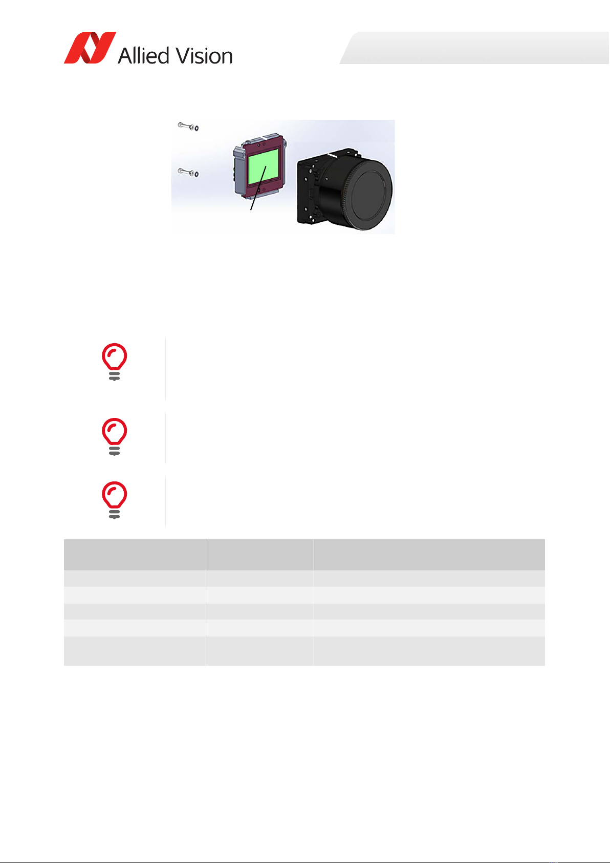
You have access to the sensor now.
9. Continue with 9.3. Removing the taped cover glass on page 12.
9.3. Removing the taped cover glass
Figure 18: sensor unit and sensor
Ease handling
• Use a magnifying glass for better view.
• Read the instructions thoroughly and keep tools at hand for camera
preparation.
Use of the term “camera” in this section
In this section, the term "camera" includes sensor units of Prosilica GT cameras.
Required tools
Before you can remove the TCG, please obtain the required tools shown below.
Required tools Tools short names Purpose
Base magnifier or microscope Magnifying glass For better view
Wooden spatula Spatula To keep the cover glass in position until removed
Precision screwdriver Screwdriver To lift up the adhesive tapes
Pinch nose pliers Pliers To pull off the adhesive tapes
Circular protection foil
(optional)
Circular protection foil To protect the sensor during camera storage
before final hardware installation
Table 3: Required tools to remove a TCG
Sensor

Preparing Cameras without
Sensor Cover Glass
Page 13 of 18
1. Place the camera on your work bench, with the sensor side facing up.
2. Place the magnifying glass above the camera, with sufficient space to access the TCG and the adhesive
tapes with tools.
3. Take the spatula with one hand.
4. With the spatula, push the cover glass down to keep the sensor protected.
Keep pushing down with the spatula until step 15.
5. Take the screwdriver with the other hand.
6. On the left side of the sensor, carefully push the tool tip of the screwdriver against the corner of the
adhesive tape until it starts to come off. Continue lifting up the corner, until pliers can get a grip.
7. Put the screwdriver aside and take the pliers.
8. Keep pushing down with the spatula until step 15.
Figure 19: Sensor with TCG (schematic view)
Figure 20: Spatula pushing down the cover glass (schematic view)
Figure 21: Screwdriver lifting up the adhesive tape (schematic view)
Sensor
Tape
Bare pixel surface
Glass
Tape
Mount
Mount
Cover glassAdhesive tape
Spatula
Screwdriver

Preparing Cameras without
Sensor Cover Glass
Page 14 of 18
9. With the pliers, grip the detached corner of the tape and slowly pull it off the cover glass and off the
sensor baseplate.
10. Strip off the tape from the pliers.
11. Put the pliers aside.
12. Repeat steps 5. to 11., until all adhesive tapes have been removed from the sensor.
13. With one hand pushing the spatula against the cover glass, take the camera into the other hand.
14. Rotate the camera with the lens mount facing down.
15. Slowly release the spatula from the cover glass until it drops out of the lens mount.
16. Continue with
• 9.4. Reassembling Prosilica GT Extended Format housing cameras on page 15 for Prosilica GT Extended
Format housing cameras
•9.5. Reassembling Prosilica GT Large Format housing cameras on page 16 for Prosilica GT Large Format
housing cameras.
Figure 22: Pliers pulling the adhesive tape off the sensor (schematic view)
Figure 23: Rotating the camera to drop the cover glass (schematic view)
Storing cameras after the cover glass has been removed
If you want to store the camera at this stage, fix a circular protection foil to the lens
mount in order to protect the sensor.
Pliers
Spatula
Camera
2
1
Preparing Cameras without
Sensor Cover Glass
Page 15 of 18
9.4. Reassembling Prosilica GT Extended Format housing cameras
1. Position sensor unit and lens mount, so that markers (c) align.
2. Keeping screws (a) and spacers in place, fit the sensor unit (b) as a unit into the lens mount (d)
3. Tighten the two M2 x 16 socket head cap screws (e) at a maximum torque of 4 lbf-in (0.45 Nm).
4. Position front assembly and body assembly, so that markers (g) align.
5. Mount the front assembly (f) to the body assembly (h).
6. Insert and tighten the four M2 x 8 socket head cap screws at a maximum torque of 4.5 lbf-in (0.51 Nm).
Figure 24: Fitting the sensor unit into the lens mount
Figure 25: Tightening the two M2 x 16 socket head cap screws
Figure 26: Mounting the front assembly to the body assembly
Figure 27: Inserting and tightening the four M2 x 8 socket head cap screws of the front assembly
b
a
d
c
ee
f g h

Preparing Cameras without
Sensor Cover Glass
Page 16 of 18
9.5. Reassembling Prosilica GT Large Format housing cameras
1. Position sensor unit (a) and lens mount (c), so that markers (b) align.
2. Fit the sensor unit (a) into the lens mount (c).
3. Put one drop of Loctite 290 threadlocker on the threads of the two M2 x 10 socket head cap screws (d).
Insert screws and spacers (d) and tighten screws at a maximum torque of 3.5 lbf-in (0.4 Nm).
4. Flip the front assembly (g) back to the body assembly (h) to approximately 45°.
5. Engage the flexible contact bar (f) to the mating contact bar.
6. Avoid bending or squeezing the ribbon cable (e):
Flip the front assembly (g) back to the body assembly (h) and close the camera.
Figure 28: Fitting the sensor unit into the lens mount
Figure 29: Inserting the two M2 x 10 socket head cap screws
Figure 30: Rejoining the front assembly with the body assembly
a
c
b
d
Camera top
e
f
h
g

Preparing Cameras without
Sensor Cover Glass
Page 17 of 18
7. Insert and tighten the four M2 x 10 socket head cap screws at a maximum torque of 4 lbf-in (0.45 Nm).
9.6. Mounting the lens
• Mount your optics according to the manual of the lens manufacturer and the Prosilica GT User Guide.
9.7. Focus recalibration
Should lens mounts have to be recalibrated for Prosilica GT cameras, follow the instructions in the user
guide.
Figure 31: Inserting the four M2 x 10 socket head cap screws of the front assembly
NOTICE
Damage to the sensor
If you want to use your camera without lens, observe 3. Safety notes on page 1.
NOTICE
Damage to sensor and lens
If the lens exceeds maximum protrusion, camera or lens may be damaged.
• To avoid damaging the sensor or the back lens, use lenses with a maximum
protrusion within camera specifications. For details, see your camera’s user
guide.
Prosilica GT User Guide
Download the Prosilica GT User Guide from www.alliedvision.com/en/support/
technical-documentation/prosilica-gt-documentation.
i

Preparing Cameras without
Sensor Cover Glass
Page 18 of 18
10. Contact us
11. Copyright and trademarks
All text, pictures, and graphics are protected by copyright and other laws protecting intellectual property.
All content is subject to change without notice. All trademarks, logos, and brands cited in this document are
property and/or copyright material of their respective owners. Use of these trademarks, logos, and brands
does not imply endorsement.
Copyright © 2022 Allied Vision Technologies GmbH. All rights reserved.
Website, email
General
www.alliedvision.com/en/contact
info@alliedvision.com
Distribution partners
www.alliedvision.com/en/avt-locations/avt-distributors
Support
www.alliedvision.com/en/support
www.alliedvision.com/en/about-us/contact-us/technical-support-repair-/-rma
Offices
Europe, Middle East, and Africa
(Headquarters)
Allied Vision Technologies GmbH
Taschenweg 2a
07646 Stadtroda, Germany
T// +49 36428 677-0 (Reception)
T// +49 36428 677-230 (Sales)
F// +49 36428 677-28
Asia-Pacific
China
Allied Vision Technologies
(Shanghai) Co., Ltd.
2-2109 Hongwell Int. Plaza
1602# ZhongShanXi Road
Shanghai 200235, China
T// +86 21 64861133
Singapore
Allied Vision Technologies Asia Pte. Ltd
82 Playfair Rd, #07-01 D'Lithium
Singapore 368001
T// +65 6634 9027
North, Central, and South America
Canada
Allied Vision Technologies Canada Inc.
300 – 4621 Canada Way
Burnaby, BC V5G 4X8, Canada
T// +1 604 875 8855
USA
Allied Vision Technologies, Inc.
102 Pickering Way - Suite 502
Exton, PA 19341, USA
Toll-free// +1-877-USA-1394
T// +1 978 225 2030
This manual suits for next models
2
Table of contents
Popular Accessories manuals by other brands


Honeywell Home
Honeywell Home DC917 Series quick guide

ROSE DISPLAYS
ROSE DISPLAYS SUPERSNAP WITH CABLE CLIP AND BALL CHAIN instruction sheet

Johnson Controls
Johnson Controls LN Series installation instructions

Aqua Computer
Aqua Computer aquagraFX Installation and user manual

Votronic
Votronic 30-110 K-FL quick guide

Hytronik
Hytronik DUAL Sense HIM13 Installation and instruction manual


