AllTrade Team Mechanix 410158 User manual

Model / Modèle
#410158
POUNDS
LIVRES
1500
ATV / MOTORCYCLE JACK
CRIC POUR MOTO / VTT
1431 Via Plata, Long Beach, CA 90810-1462
www.alltradetools.com
©Copyright 2007 ALLTRADE TOOLS LLC Rev. 1
FOR CUSTOMER SERVICE
POUR LE SERVICE APRÉS VENTE
OU DU CONSOMMATEUR
1-800-423-3598
Please retain these instructions for future reference.
If you encounter any problems or difficulties,
please contact our toll free Customer Service Department at:
1-800-423-3598
1-310-522-9008 (California only)
Prière de conserver ces instructions pour pouvoir y référer à l'avenir.
En cas de problèmes ou de difficultés,
prière de contacter notre Service Après-Vente au numéro d’appel gratuit:
1-800-423-3598
1-310-522-9008 (En Californie seulement)

SPECIFICATIONS
Max Capacity 1,500 lbs.
Base Length 31" (785 mm)
Base Width 14" (360 mm)
Base Height 11.8" (300 mm)
Min. Lift Height 4-1/2"
Max. Lift Height 14-1/2"
Overall Weight 65 lbs.
32
No. Description Qty.
1 Caster Assembly 2
2 Safety Lock Screw 2
3 Lock Pawl 2
4 Frame 1
5 Front Wheels 2
6 Saddle Platform 1
7 Rubber Pad 2
8 Radius Link 2
9 Load Frame 1
10 Bolt (M8 x 30) 1
11 Handle 1
12 Hydraulic Ram 1
13 R Type Locking Pin 1
14 Lock Pin 1
15 Bolt (M8 x 30) 1
16 Pump Pedal 1
17 Bolt (M8 x 25) 2
18 Washer M8 2
19 Release Pedal 1
20 Ram Platform 1
PARTS LIST
IMPORTANT SAFETY INFORMATION
READ ALL SAFETY WARNINGS BEFORE OPERATION!
FAILURE TO OBEY THESE WARNINGS MAY RESULT IN LOSS OF LOAD, DAMAGE TO JACK,
AND OR JACK FAILURE RESULTING IN PERSONAL INJURY OR PROPERTY DAMAGE.
ATV/MOTORCYCLE JACK
•STUDY, UNDERSTAND, AND FOLLOW ALL INSTRUCTIONS BEFORE OPERATING THIS DEVICE.
•FAILURE TO HEED THESE INSTRUCTIONS MAY RESULT IN PERSONAL INJURY AND/OR
PROPERTY DAMAGE.
•USE STRAPS WITH 150% RATED CAPACITY OF WEIGHT OF LOAD, STRAPS NOT INCLUDED.
•DO NOT EXCEED RATED CAPACITY.
•USE ONLY ON HARD LEVEL SURFACE.
•BEFORE MOVING, LOWER THE LOAD TO THE LOWEST POSSIBLE POINT.
•USE THE SAFETY ARMS WHEN LOAD IS RAISED TO PREVENT ACCIDENTAL LOWERING.
•NO ALTERATIONS SHALL BE MADE TO THIS PRODUCT.
•LOAD SADDLE PLATFORM EQUALLY.
•ONLY ATTACHMENTS AND OR ADAPTORS SUPPLIED BY MANUFACTURER SHALL BE USED.
•LIFT ONLY ON AREAS OF THE VEHICLE AS SPECIFIED BY VEHICLE MANUFACTURER.

ASSEMBLY INSTRUCTIONS
Installing Hydraulic Ram
1. Attach hydraulic ram (12) to the ram platform (20) with bolts (17)
and washers (18).
Attaching Lock Bar, Hydraulic Ram and Foot Pedal
1. To install lock bar, remove R type locking pins (13) and washers
from jack posts. Align lock bar with jack posts on both sides of the
jack and replace R type locking pins (13) and washers.
2. Remove R type locking pin (13) and lock pin (14) from ram, raise
load frame (9) by hand and align the head of the hydraulic ram (12)
with the tab holes in the low center of the load frame. Replace lock
pin (14) and secure with R type locking pin (13).
3. Insert foot pedal (16) into ram. Use screw (15) to fasten pedal in
place.
OPERATING INSTRUCTIONS
Mounting Vehicle On Lift
1. Lower the jack completely. This should allow you to easily roll it
under the vehicle.
Note: Read your Vehicle Owner’s Manual to
determine the recommended lift points for your specific vehicle.
2. Make sure that your vehicle is properly balanced. Load saddle
platform equally.
Operating Lift
1. Make sure that vehicle is properly balanced on lift saddle platform.
2. While watching to make sure it is safe to do so, pump foot pedal
repeatedly to lift the vehicle to the desired height. Make sure the
vehicle is lifted high enough to engage the lock bar into its lock
bar detents.
3. Immediately after lifting vehicle, support the vehicle with tie down
straps. Attach your vehicle securely to the lift, using appropriate
straps (straps with 150% rated capacity of weight of load
recommended, straps not included).
Bolts
Lowering Vehicle
1. Be sure it is safe to lower your vehicle by clearing area of tools
and equipment. Make sure everyone is clear of the lift.
2. Raise the jack high enough to release the lock bar from its detent
and secure lock bar under holding cotter pin.
3. While watching to make sure it is safe to do so, hold foot pedal
down to lower the
vehicle to the ground.
Never work on the vehicle, or leave unattended if the lock bar is not in place, and if sufficient tie down
straps are not holding the vehicle firmly in place.MAINTENANCE AND INSPECTION
1. Visual inspections shall be made before each use of the jack by checking for abnormal
conditions such as cracked wheels, leaks and damaged, loose or missing parts.
2. Other inspection shall be made per product operating instructions.
3. Each jack shall be inspected immediately if it is believed to have been subjected to an
abnormal load or shock.
4. Owners and or operators should be aware that repair of this equipment may require special knowledge
and facilities.
5. It is recommended that an annual inspection of the jack be made and that any defective parts, decals,
or safety labels or signs be replaced with manufacturer’s specified parts.
6. Any jack that appears to be damaged in any way, is found to be worn, or operates abnormally shall be
removed from service until repaired.
7. Because of the potential hazards associated with this type of equipment, no alterations shall
be made to the product.
8. Do not mix different types of oil together. When filling the jack with oil, do not permit dirt
or any other substance to enter the hydraulic system.
SYMPTOMS
Will not lift load See #1, #2 and #3 under the Troubleshooting section
Will not hold load See #3 under the Troubleshooting section
Will not lift to full height See #1 and #2 under the Troubleshooting section
Pump feels “spongy” under load See #1 and #2 under the Troubleshooting section
Handle raises under load See #3 under the Troubleshooting section
Handle lowers under load See #3 under the Troubleshooting section
TROUBLESHOOTING
1. The hydraulic ram may be low on fluid. With the jack on a level surface and in the down position,
remove the filler plug and add clean hydraulic jack fluid to the level of the filler hole.
2. The hydraulic ram may have trapped air. Open the release valve a minimum of two full turns. Pump the
handle a minimum of 20 strokes to purge the air from the system.
3. Valves may not be closing properly. To seat the valves: A) Close the release valve. B) With the ram fully
lowered, manually lift the boom as high as possible. C) Open the release valve and allow the boom to
descend to the lowered position.
5
4
14
12
9
13 13
16
15

8
7
SPÉCIFICATIONS
Capacité max. 1500 lb (681 kg)
Longueur du socle 31 po (785 mm)
Largeur du socle 14 po (360 mm)
Hauteur du socle 11,8 po (300 mm)
Hauteur de levage min. 4-1/2 po
Hauteur de levage max 14-1/2 po
Poids total 65 lb (29,5 x kg)
No. Description Qté.
1 Roulettes 2
2 Cliquet de blocage 2
3 Vis de blocage de sécurité 2
4 Châssis 1
5 Roulettes avant 2
6 Sellette d’appui 1
7 Coussinets en caoutchouc 2
8 Transmission radiale 2
9 Cadre de levage 1
10 Boulon (M8 x 30) 1
11 Poignée 1
12 Vérin hydraulique 1
13 Goupille fendue 1
14 Goupille de sécurité 1
15 Boulon (M8 x 30) 1
16 Pédale de pompage 1
17 Boulon (M8 x 25) 2
18 Rondelle M8 2
19 Pédale de déblocage 1
20 Plate-forme du vérin 1
NOMENCLATURE DES PIÈCES
INFORMATIONS IMPORTANTES CONCERNANT LA SÉCURITÉ
LIRE ATTENTIVEMENT TOUS LES AVERTISSEMENTS AVANT L’EMPLOI !
LE NON RESPECT DE CES AVERTISSEMENT PEUT ENTRAÎNER LA PERTE DE LA CHARGE, ENDOMMAGER
LE CRIC ET/OU PROVOQUER DES DÉGÂTS MATÉRIELS AINSI QUE DES BLESSURES CORPORELLES POUVANT
ÊTRE MORTELLES.
CRIC POUR MOTO/VTT
• ÉTUDIER ATTENTIVEMENT ET RESPECTER TOUTES CES INSTRUCTIONS AVANT D’UTILISER CE DISPOSITIF.
• LE NON RESPECT DE CES INSTRUCTIONS PEUT OCCASIONNER DES BLESSURES CORPORELLES GRAVES
ET/OU DES DOMMAGES CORPORELS.
• UTILISER DES SANGLES AYANT UNE CAPACITÉ NOMINALE DE REPRISE DE CHARGE DE 150%, SANGLES
NON COMPRISES.
• NE PAS DÉPASSER LA CAPACITÉ NOMINALE.
• UTILISER UNIQUEMENT SUR UNE SURFACE DURE ET À NIVEAU.
• AVANT TOUT DÉPLACEMENT, ABAISSER LA CHARGE AU POINT LE PLUS BAS.
• UTILISER LES BRAS DE SÉCURITÉ EN SOULEVANT LA CHARGE POUR ÉVITER TOUTE DESCENTE
ACCIDENTELLE.
• N’ALTÉRER CE PRODUIT EN AUCUNE FAÇON.
• RÉPARTIR UNIFORMÉMENT LA CHARGE SUR LA SELLETTE D’APPUI.
• N’UTILISER QUE LES FIXATIONS OU ADAPTATEURS FOURNIS PAR LE FABRICANT.
• SOULEVER UNIQUEMENT AUX POINTS INDIQUÉS PAR LE CONSTRUCTEUR DU VÉHICULE.

INSTRUCTIONS DE MONTAGE
Installation du vérin hydraulique
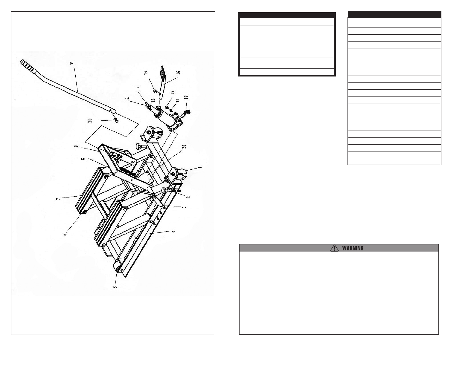
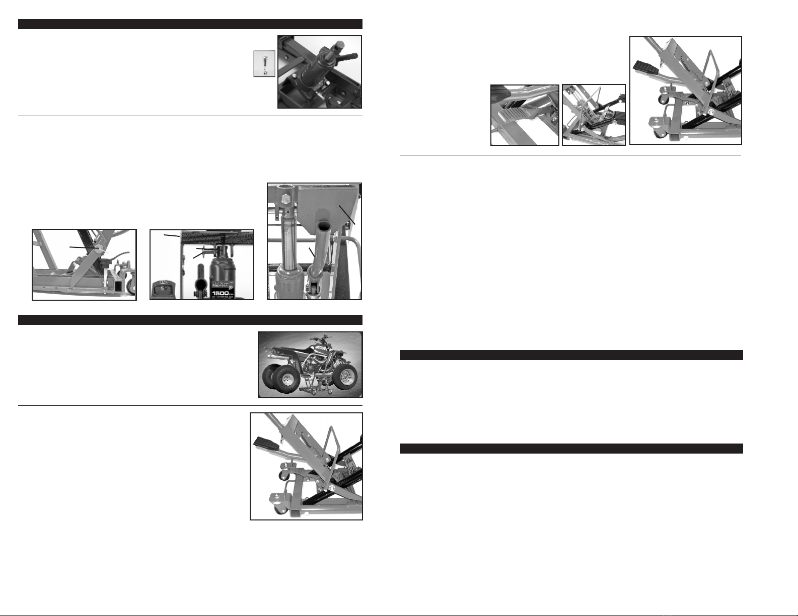
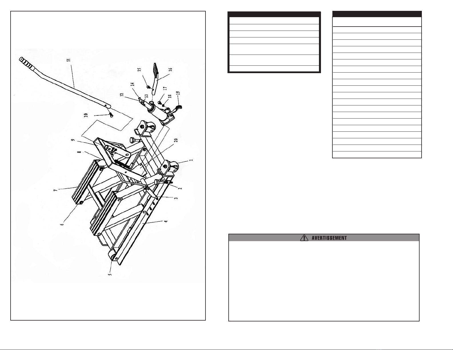
1. Fixer le vérin hydraulique (12) sur la plate-forme du vérin (20)
à l’aide des boulons (17) et rondelles (18).
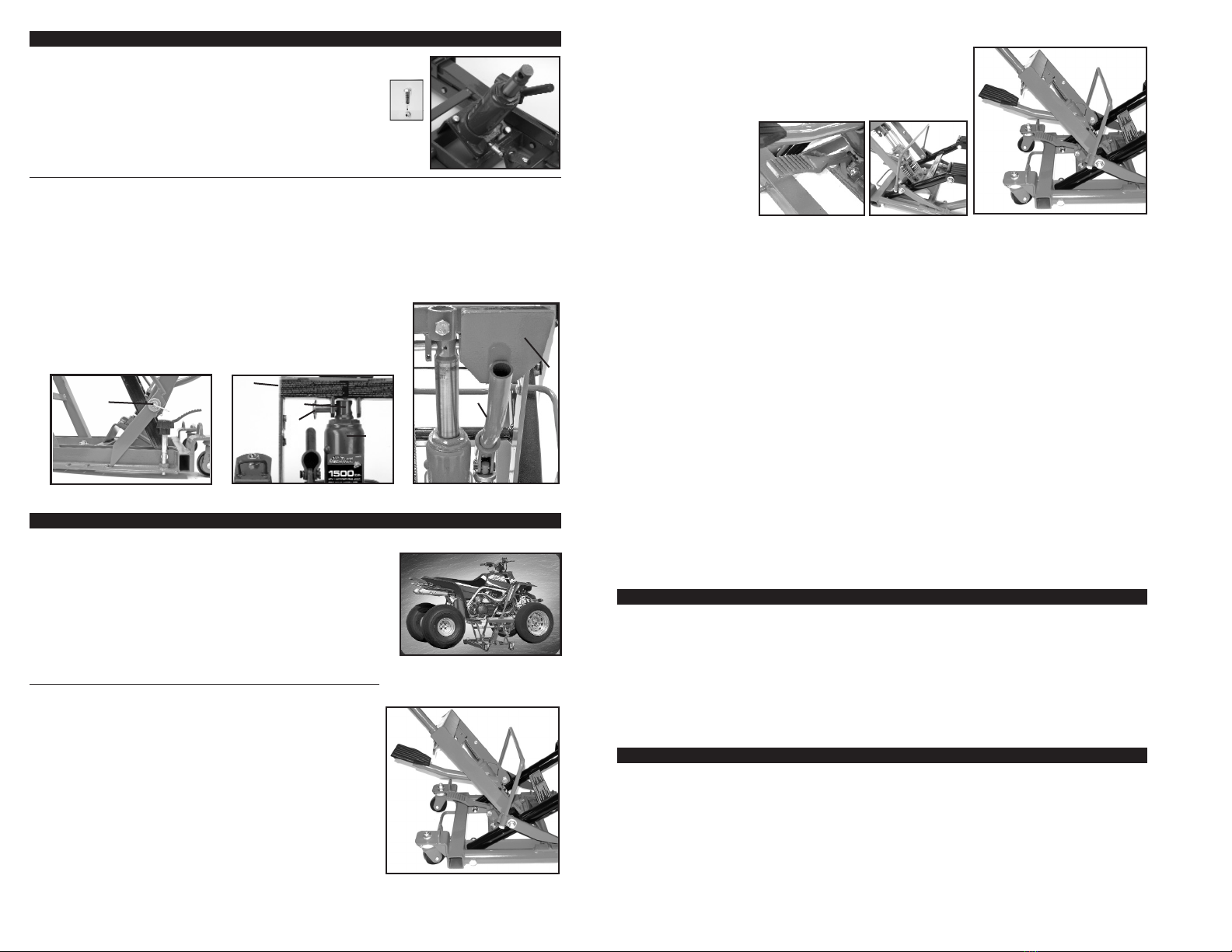
Fixation de la barre de verrouillage, du vérin hydraulique et de la pédale
1. Pour installer la barre de verrouillage, enlevez les goupilles fendue
(13) et rondelles des poteaux de plot. Alignez la barre de verrouillage
avec des poteaux de plot des deux côtés du plot et replacer les
goupilles fendue (13) et rondelles.
2. Retirer la goupille fendue (13) et la goupille de sécurité (14), abaisser
le cadre de levage (9) et aligner la tête du vérin hydraulique (12) avec
les trous du support situés sur la partie centrale inférieure du cadre
de levage. Remettre la goupille de sécurité (14) et la fixer avec la
goupille fendue (13).
3. Insérer la pédale (16) dans le vérin. Utiliser la vis (15) pour fixer la
pédale en position.
MODE D’EMPLOI
Mise en place du véhicule sur le dispositif de levage
1. Descendre complètement le cric. Ceci devrait permettre de le faire
rouler facilement sous le véhicule. Remarque : Consulter le manuel
du propriétaire du véhicule pour déterminer quels sont les points
de levage recommandés pour le véhicule en question.
2. Vérifier que le véhicule est bien équilibré. Répartir la charge
uniformément sur la sellette d’appui.
Actionnement du dispositif de levage
1. S’assurer que le véhicule est bien équilibré sur la sellette d’appui.
2. Tout en vérifiant que la manoeuvre ne présente aucun problème,
actionner à plusieurs reprises sur la pédale pour soulever le
véhicule à la hauteur voulue. Vérifier que le véhicule est suffisam-
ment haut pour engager la barre de verrouillage dans ses crans.
3. Aussitôt après avoir levé le véhicule, le maintenir avec des sangles
d’attache. Maintenir fermement le véhicule sur le dispositif de
levage à l’aide des sangles appropriées (sangles ayant une capac-
ité nominale de reprise de charge de 150%, non incluses).
Boulons
Descente du véhicule
1. Vérifier qu’il est possible de descendre le véhicule en éloignant
au préalable tout outil et materiel de l’aire de travail. S'assurer
que personne n'est à proximité du dispositif de levage.
2. Lever suffisamment le cric pour retirer la barre de verrouillage de
ses crans, puis la maintenir fermement avec la goupille fendue.
3. Tout en vérifiant que la
manoeuvre ne
présente aucun prob-
lème, actionner à
plusieurs reprises
sur la pédale pour
abaisser le véhicule à
la hauteur voulue.
Ne jamais travailler sur le véhicule ni s’en éloigner tant que la
barre de verrouillage n’est pas installée et qu’il n’est pas ferme-
ment maintenu en place par des sangles d’attache.
ENTRETIEN ET INSPECTION
1. Procéder à une inspection visuelle du vérin avant chaque utilisation pour s’assurer qu'il n’y a pas de
roues abîmées, des fuites, des pièces endommagées, desserrées ou manquantes.
2. Effectuer toute autre verification préconisée dans le mode d’emploi du produit en question.
3. Chaque vérin doit être inspecté immédiatement si l’on soupçonne qu’il a été soumis à une charge anor-
malement élevée ou en cas de choc.
4. Les propriétaires et utilisateurs doivent savoir que la réparation de ce matériel peut nécessiter une
expertise et des installations spéciales.
5. Il est recommandé d’effectuer une inspection annuelle du vérin et de remplacer toute pièce, autocollant
ou étiquette de mise en garde endommagée ou usagée par les pièces de rechange préconisées par le
fabricant.
6. Tout vérin qui semble avoir subi un quelconque dommage, est usé ou qui fonctionne anormalement,
doit être mis hors service sur-le-champ.
7. En raison des risques éventuels associés à ce type de matériel, aucune modification ne doit être
apportée à ce produit.
8. Ne pas mélanger deux types d’huile différentes. Lorsque l’on remet de l’huile dans le vérin, s’assurer
qu’aucune saleté ou autre substance ne puisse pénétrer dans le système hydraulique.
SYMPTOMES
Levage impossible de la charge Voir nº 1, 2 et 3 sous Guide de dépannage
Affaissement de la charge Voir nº 3 sous Guide de dépannage
Levage incomplet Voir nº 1 et 2 sous Guide de dépannage
Sensation de pompe « spongieuse »
sous la charge Voir nº 1 et 2 sous Guide de dépannage
Relèvement de la poignée sous la charge Voir nº 3 sous Guide de dépannage
Abaissement de la poignée sous la charge Voir nº 3 sous Guide dépannage
GUIDE DE DÉPANNAGE
1. Il est possible que le niveau de liquide en le vérin hydraulique soit insuffisant. Mettre le cric sur une
surface à niveau et en position basse, retirer le bouchon du réservoir et ajouter du liquide neuf pour
cric hydraulique jusqu’au niveau du trou de remplissage.
2. Il est possible qu’il y ait une prise d’air sur le vérin hydraulique. Ouvrir le purgeur sur deux tours com-
plets minimum. Actionner la poignée au minimum 20 fois pour purger l’air du système.
3. Il est possible que les valves ne ferment pas complètement. Pour régler les valves : A) Fermer le
purgeur. B) Avec le cric en position totalement basse, lever manuellement le bras aussi que possible.
C) Ouvrir le purgeur et laisser le bras redescendre en position basse.
10
9
14
12
9
13 13
16
15
Table of contents
Languages:
Other AllTrade Jack manuals
Popular Jack manuals by other brands

Clarke
Clarke CTJ3GLS Operation & maintenance instructions

Hercus
Hercus HK Series Maintenance and operating instructions

HWH
HWH 100 Series Operator's manual

Sealey
Sealey WS570.V2 instructions

ULTIMATE SPEED
ULTIMATE SPEED 289553 Operation and safety notes

Husky
Husky 82022 Assembly, Installation, Operation and Maintenance Instructions

Clarke
Clarke CTJ2000LPB Operation & maintenance instructions

GMV
GMV 9100 Installation

Pramac
Pramac GS PRO RA 25S4 2000X525 manual

Cornwell Tools
Cornwell Tools CTJ35NG operating manual

K Tool International
K Tool International KTI-63505A owner's manual

K Tool International
K Tool International KTI-63101A owner's manual