Jackco 66310 User manual

Model 66310 - Two-Speed Service Jack
Max. Capacity: 3 Tons
Application: Designed to lift a wide range of motor vehicles.
www.jackco.com
15
23
21
22
5
6
25
29
8
32
33
1
16
10
11
20
31
12
18
19
26
9
27
28
24
23 14
35
39
42
40
41
36
37
38
34
7
17
30
18
26
7
Refer to sheet 3 for
hydraulic assembly
detail.
Visit our website at: http://www.jackco.com
WARNING
!
Read this material before using this product. Failure to do so can result in serious injury. SAVE THIS MANUAL.
This product may contain chemicals know
to the State of California to cause cancer,
birth defects, or other reproductive harm.
!Prop. 65 Warning
for California Residents

Parts List
Prop. 65 Warning
for California Residents
Item No. Qty. Description
1 2 Circlip (20)
2 2 Washer (20)
3 2 Front Wheel
5 2 Circlip (18)
6 2 Pivot Support Rod
7 4 Circlip (25)
8 2 Pivot Support Rod Screw
9 1 Saddle
10 1 Saddle Screw
11 1 Rubber Pad
12 1 Lift Arm Shaft
14 1 Load Block
15 1 Pin (A4 x 55)
16 1 Cover Plate
17 1 Return Spring
18 2 Tie Rod
19 1 Handle Yoke Bottom Half
20 1 Handle Yoke Connection Pin
21 1 Handle Yoke Top Half
22 1 Hydraulic Assembly
23 1 Spring
24 1 Handle Yoke Lock
25 1 Rivet
26 5 Washer (8)
27 1 Screw (M8 x 16)
28 1 Roller Pin
29 2 Circlip (12)
30 1 Roller
31 1 Handle Rubber Grip
32 2 Handle Yoke Screw
33 2 Washer (18)
34 4 Nut (16)
35 4 Washer (16)
36 4 Screw (M5 x 12)
37 4 Washer (12)
38 4 Screw (M12 x 20)
39 2 Rear Caster Assembly
40 4 Screw (M8 x 20)
41 1 Upper Handle
42 1 Lower Handle

Replacement Parts Kits
No. 66310-01 Saddle Kit contains:
Item
No. Qty. Description
9 1 Saddle
10 1 Saddle Screw
11 1 Rubber Pad
No. 66310-03 Caster Kit contains:
Item
No. Qty. Description
34 2 Nut (16)
35 2 Washer (16)
39 2 Rear Caster Assembly
No. 66310-04 Wheel Kit contains:
Item
No. Qty. Description
1 2 Circlip (20)
2 2 Washer (20)
3 2 Front Wheel
No. 66310-09 Handle Kit contains:
Item
No. Qty. Description
31 1 Handle Rubber Grip
41 1 Upper Handle
42 1 Lower Handle
No. 66310-11 Handle Retaining Nut
Kit contains:
Item
No. Qty. Description
26 1 Washer (8)
27 1 Screw (M8 x 16)
No. 66310-05 Hydraulic Unit Kit
contains:
Item
No. Qty. Description
15 1 Pin (A4 x 55)
22 1 Hydraulic Unit
37 4 Washer (12)
38 4 Screw (M12 x 20)
No. 66310-02 Saddle Pad contains:
Item
No. Qty. Description
11 1 Rubber Pad
No. 66310-06 Hardware Kit contains:
Item
No. Qty. Description
5 2 Circlip (18)
6 2 Pivot Support Rod
7 4 Circlip (25)
8 2 Pivot Support Rod Screw
16 1 Cover Plate
17 1 Return Spring
18 2 Tie Rod
26 5 Washer (8)
34 4 Nut (16)
35 4 Washer (16)
36 4 Screw (M5 x 12)
40 4 Screw (M8 x 20)
No. 66310-10 Handle Pivot Kit
contains:
Item
No. Qty. Description
19 1 Handle Yoke Bottom Half
20 1 Handle Yoke
Connection Pin
21 1 Handle Yoke Top Half
23 1 Spring
24 1 Handle Yoke Lock
25 1 Rivet
26 1 Washer (8)
27 1 Screw (M8 x 16)
28 1 Roller Pin
29 2 Circlip (12)
30 1 Roller
32 2 Handle Yoke Screw
33 2 Washer (18)
No. 66310-07 Load Block Kit contains:
Item
No. Qty. Description
7 2 Circlip (25)
14 1 Load Block
15 1 Pin (A4 x 55)
No. 66310-08 Main Pivot Pin Kit
contains:
Item
No. Qty. Description
7 2 Circlip (25)
12 1 Lift Arm Shaft
Refer to operating instructions included with this product for detailed information about
operation, testing, disassembly, reassembly, and preventive maintenance.
Address additional questions to our Technical Services Department at (888) 4JACKCO.
Items found in this parts list have been carefully tested and selected by Jackco.
To ensure the best performance of this product, use only genuine Jackco replacement parts.

Hydraulic Assembly
43
45
46
49
50
52
54
55
56 57
58 59
60
61
62
63
64
65
66
67
68
69
70
71
72
73
74
75
76
77
78
79
80
81
82
61
60
64
65
61
60
64
(2x)

Hydraulic Assembly Parts List
Item No. Qty. Description
43 1 Reservoir Bottom Seal Ring
45 1 Reservoir Top Seal Ring
46 1 O-Ring (29.6 x 3.5)
49 1 O-Ring Retainer
50 1 O-Ring (31 x 4.6)
52 1 Cylinder Copper Seal Ring
53 1 Hydraulic Base
54 1 Steel Ball (7.5 mm)
55 1 Low Relief Valve Spring
56 1 Steel Ball (4 mm)
57 1 Spring Retainer
58 1 High Relief Valve Spring
59 1 High Relief Valve Set Screw
60 3 O-Ring (7.1 x 1.8)
61 3 Relief Valve Cover Screw
62 1 Steel Ball (8 mm)
63 1 Low Relief Valve Set Screw
64 4 Steel Ball (5 mm)
65 2 Piston Housing Copper Seal Ring
66 1 High Pressure Piston Housing
67 1 O-Ring
68 1 Circlip (15 x 11 x 3)
69 1 High Pressure Piston
70 1 High Pressure Piston Return Spring
71 1 High Pressure Piston Dust Cover
72 1 Return Spring Holder (15)
73 1 Circlip (15)
74 1 U-Joint
75 1 Steel Ball (6 mm)
76 1 Low Pressure Piston Housing
77 2 O-Ring (15 x 2.65)
78 1 Low Pressure Piston
79 1 Low Pressure Piston Return Spring
80 1 Low Pressure Piston Dust Cover
81 1 Return Spring Holder (20)
82 1 Circlip (20)

Replacement Parts Kits for the Hydraulic Assembly
Bleeding Air from the System
No. 66310-12 Seal Kit contains:
Item
No. Qty. Description
43 1 Reservoir Bottom Seal Ring
45 1 Reservoir Top Seal Ring
46 1 O-Ring (29.6 x 3.5)
49 1 O-Ring Retainer
50 1 O-Ring (31 x 4.6)
52 1 Cylinder Copper Seal Ring
60 3 O-Ring (7.1 x 1.8)
65 2 Piston Housing Copper Seal Ring
67 1 O-Ring
77 2 O-Ring (15 x 2.65)
No. 66310-14 U-Joint Kit contains:
Item
No. Qty. Description
74 1 U-Joint
75 1 Steel Ball (6 mm)
No. 66310-13 Hydraulic Hardware Kit contains:
Item
No. Qty. Description
54 1 Steel Ball (7.5 mm)
55 1 Low Relief Valve Spring
56 1 Steel Ball (4 mm)
57 1 Spring Retainer
58 1 High Relief Valve Spring
59 1 High Relief Valve Set Screw
60 3 O-Ring (7.1 x 1.8)
61 3 Relief Valve Cover Screw
62 1 Steel Ball (8 mm)
63 1 Low Relief Valve Set Screw
64 2 Steel Ball (5 mm)
No. 66310-15 Pump Station Kit contains:
Item
No. Qty. Description
64 2 Steel Ball (5 mm)
65 2 Piston Housing Copper Seal Ring
66 1 High Pressure Piston Housing
67 1 O-Ring
68 1 Circlip (15 x 11 x 3)
69 1 High Pressure Piston
70 1
High Pressure Piston Return Spring
71 1 High Pressure Piston Dust Cover
72 1 Return Spring Holder (15)
73 1 Circlip (15)
76 1 Low Pressure Piston Housing
77 2 O-Ring (15 x 2.65)
78 1 Low Pressure Piston
79 1 Low Pressure Piston Return Spring
80 1 Low Pressure Piston Dust Cover
81 1 Return Spring Holder (20)
82 1 Circlip (20)
Air can accumulate within a hydraulic system during shipment or if the oil supply runs too low. This entrapped air causes
the jack to respond slowly or feel “spongy.” The following procedure bleeds air from the system.
1. Remove the jack from service, and place it on a level surface.
2. Open the release valve by turning the handle all the way counterclockwise (CCW).
3. Pump the handle six full strokes.
4. Close the release valve by turning the handle all the way clockwise (CW).
5. Pump the handle until the lift arm is fully extended.
6. Lower the lift arm by turning the handle all the way counterclockwise (CCW).
7. Test the jack for normal operation. If the saddle doesn’t rise to the correct height, repeat Steps 2–6. If this doesn’t
solve the problem, call the Jackco Technical Services Dept. at (888) 4JACKCO.

Safety Precautions
Operating Instructions
CAUTION: To prevent personal injury and damage to equipment,
•Study, understand, and follow all warnings and instructions. If the operator cannot read this
document, operating instructions and safety precautions must be read and discussed in
the operator’s native language.
•Before using the service jack to lift a vehicle, refer to the vehicle service manual to determine
recommended lifting surfaces on the vehicle chassis.
•Wear eye protection that meets ANSI Z87.1 and OSHA standards.
•Inspect the jack before each use; do not use the jack if it’s damaged, altered, or in poor
condition. Take corrective action if any of the following conditions are found: cracked or
damaged housing; excessive wear, bending,or other damage;leaking hydraulic fluid; scored
or damaged piston rod; loose hardware; modified or altered equipment.
•A load must never exceed the rated lifting capacity of the jack.
•Use the jack on a hard, level surface. The jack must be free to roll without obstruction while
lifting or lowering the vehicle.The wheels of the vehicle must be in the straight-ahead position,
and the hand brake released.
•Use the jack for lifting purposes only. Stay clear of a lifted load. Place support stands under
the axles before working on the vehicle. Do not move or dolly the vehicle while on the jack.
•Center the load on the jack saddle. Off-center loads can damage seals and cause jack failure.
Lift only dead weight.
•Do not use blocks or other extenders between the saddle and the load being lifted.
•Do not modify the jack or use adapters unless approved or supplied by Jackco.
•Lower the jack slowly and carefully while watching the position of the jack saddle.
•Use only automatic transmission fluid. The use of alcohol, hydraulic brake fluid, or transmission oil could
damage seals and result in jack failure.
This guide cannot cover every situation, so always do the job with safety first.
Setup
1. Loosen the screw on the front of the handle socket.
2. Grease the socket opening. Insert the handle.
3. Torque the screw to 120 in. lbs.
Operation
1. Close the release valve by turning the handle clockwise (CW) as far as it will go.
2. Position the jack under the vehicle. CAUTION: Use the manufacturer’s recommended lifting points on the chassis.
3. Pump the jack handle to raise the saddle to the contact point.
3. Check the placement of the jack; the load must be centered on the jack saddle. CAUTION : Avoid wheel obstructions
such as gravel, tools, or uneven expansion joints.
4. Finish lifting the vehicle by pumping the handle. Do not attempt to raise the jack beyond its travel stops.
5. Place approved support stands under the vehicle at points that will provide stable support. Before making repairs on
the vehicle, lower it onto the support stands by slowly and carefully turning the handle counterclockwise (CCW).

Preventive Maintenance
CAUTION: The greatest single cause of failure in hydraulic equipment is dirt. Keep the service jack clean and well
lubricated to prevent foreign matter from entering the system. If the jack has been exposed to rain, snow, sand, or grit,
it must be cleaned before it is used.
1. Store the jack in a well-protected area where it will not be exposed to corrosive vapors, abrasive dust, or any other
harmful elements.
2. Regularly lubricate the moving parts in the wheels, arm, and handle.
3. Replace the oil in the reservoir at least once per year. To check the oil level, lower the lift arm completely. Remove
the rubber filler plug. Oil level should be at the bottom of the filler plug hole. If necessary, add automatic transmission
fluid, and install the filler plug. CAUTION: The use of alcohol or hydraulic brake fluid could damage the seals
and result in jack failure.
4. Inspect the jack before each use. Take corrective action if any of the following problems are found:
a. cracked, damaged housing c. leaking hydraulic fluid e. loose hardware
b. excessive wear, bending, other damage d. scored, damaged piston rod f. modified equipment
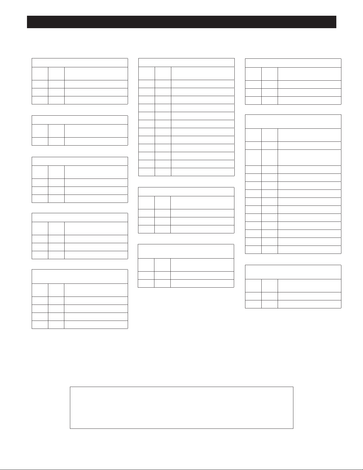
Troubleshooting Guide
Limited One Year Warranty
Repair procedures must be performed in a dirt-free environment by qualified personnel who are familiar with this
equipment. CAUTION: All inspection, maintenance, and repair procedures must be performed when the jack is
free of a load (not in use).
Trouble Cause Solution
Jack does not lift
1. Release valve is open. 1. Close release valve.
2. Low/no oil in reservoir. 2. Fill with automatic transmission fluid
and bleed system. Refer to Bleeding Air
from the System
3. Air-locked system. 3. Refer to Bleeding Air from the System .
4. Load is above capacity of jack. 4. Use correct equipment.
5. Delivery valve and/or bypass valve
not working correctly.
5. Clean valve to remove dirt or foreign
matter. Replace oil.
6. Packing worn out or defective. 6. Replace packing.
Jack lifts only partially
1. Too much or not enough oil. 1. Check oil level.
Jack advances slowly
1. Pump not working correctly. 1. Rework pump.
2. Leaking seals. 2. Replace seals. Seal kit No. 577275 is
available from Jackco.
Jack lifts load, but doesn't hold
1. Cylinder packing is leaking. 1. Replace packing.
2. Valve not working correctly
(suction,delivery, release, or bypass).
2. Inspect valves. Replace if necessary.
3. Air-locked system. 3. Refer to Bleeding Air from the System .
Jack leaks oil
1. Worn or damaged seals. 1. Replace seals. Seal kit No. 577275 is
available from Jackco.
Jack will not retract
1. Release valve is closed. 1. Open release valve all the way
counterclockwise (CCW). May be
necessary to clean release valve.
Jack retracts slowly
1. Cylinder damaged internally. 1. Send jack to Jackco
2. Return spring(s) is damaged. 2. Replace return spring(s).
3. Link section is binding. 3. Lubricate link sections.
Jackco Transnational Inc. (Jackco) warrants all Jackco equipment and tools to the original purchaser against any manufacturing defect in material
or workmanship for a period of one (1) year from the original date of purchase. If the defective equipment or tool is determined to be covered
under this warranty, it shall be repaired or replaced at manufacturer's discretion without charge, provided that the equipment or tool must be
returned with proof of purchase to the dealer and freight prepaid, if returned to the manufacturer. This warranty shall not apply to damage due to
accident, negligent use, lack of maintenance, abuse or applications other than the specific function the equipment or tool is designed for.
No other warranties, expressed or implied, including those of merchantability or fitness for particular purpose shall be applicable to Jackco except
as specifically stated herein. In no event shall Jackco be liable to any party for any special, direct, indirect, consequential, punitive damage of any
nature caused by the sale or use of the equipment or tool.
Note: This warranty gives the original purchaser specific legal rights which may very from state to state.
Table of contents
Other Jackco Jack manuals