ALMACRAWLER JIBBI PRIMO Series User guide

1300 551 108 | efleet@alfasihire.com.au
Carrum Downs (HQ)
(03) 8795 2999
Hunter Valley, NSW
(02) 9589 6200
Sydney, NSW
(02) 9589 6200
Brisbane, QLD
(07) 3370 2800
Derrimut, VIC
(03) 8795 2999
Gold Coast, QLD
(07) 3370 2800
Mackay, QLD
(07) 3370 2800
Karratha, WA
(08) 6187 3000
1300 551 108 | info@alfasihire.com.au | alfasihire.com.au
JIBBI
1250 EVO
PATENT PENDING
JIBBI 1890 PRIMO
Crawler Telescopic Boom

18m
14m
JIBBI 1890 PRiMO
FULL
ELECTRIC
DRIVE
Completely reimagined controller for a streamlined user
experience based on industry accepted standards and rental
sector needs. Two USB recharging stations available on each
controller.
working
height
travel
height
PRiMO
SELF-PROPELLED
SELF-LEVELLING
FULL ELECTRIC
PRiMO. The rst full electric, self-
levelling, tracked telescopic boom with
electric drive and fully removable power
pack.
Designed to eliminate jobsite
obstacles, with an 18m working height,
it can safely be driven up to 14m and
15° lateral and logitudinal inclination,
drastically enhancing eciency and
operator productivity.
Innite battery autonomy with the
innovative interchangeable, fully
removable Power Pack that can be
easily transported to allow recharge.

18m
AES
ANTI-ENTRAPMENT
SYSTEM
WORK
LIGHTS
ATS
FULL ELECTRIC
REMOVABLE
POWER PACK
Lithium
330Ah 48V
Lithium
440Ah 48V
UAS
Lead acid
420Ah 48V
350 Kg 6,5 h
300 Kg 5,0 h
720 Kg 6,5 h
BATTERY TYPE
TIPO BATTERIA
WEIGHT
PESO
RECHARGE
RICARICA
The ATS zero maintenance track tensioning system is directly
connected to and controlled by the main hydraulic system.
The UAS sensors safeguard the aerial and travel operations by monitoring the
area in front and behind the tracks, on the tail swing, and above and below
the basket, preventing collisions with obstacles and offering pothole and
drop-off protection.
AUTOMATIC
TENSIONER
SYSTEM
LUCI OPERATIVE
ULTRASONIC
ANTI-COLLISION
SYSTEM
WITH COMPLETELY ELC
LTH
IP67
STANDARD STANDARD
Innite autonomy with our fully removable Power Pack with integrated forklift pockets,
a new and innovative power option. Each unit can be easily substituted and taken for
recharge off-site. Choose between interchangeable AGM or Lithium battery packs!
The AES anti-entrapment system
is designed to prevent serious injury by stopping the unit but
Work year-round in any condition
EV Type 2 110 / 220 VAC *
*AUTOMATIC CHARGING POWER SETTING ACCORDING TO MAINS
VOLTAGE

Technical data JIBBI 1890 PRiMO Dati tecnici
Max working height 17,90 m Altezza massima di lavoro
Max height basket oor 15,90 m Altezza piano calpestio
Max moving height 13,80 m Altezza di traslazione
Max outreach (load 140 kg) 9,92 m Sbraccio massimo (carico 140 Kg)
Max outreach (250 kg) 8,32 m Sbraccio massimo (carico 250 Kg)
Rotation angle +/- 190° Angolo di rotazione torretta
Basket size 1,80 x 0,70 m Dimensioni navicella
Basket rotation angle +/- 70° Angolo di rotazione navicella
Max basket capacity 250 Kg (2 p.) Portata massima in navicella
Length in stowed position 5,86 m Lunghezza richiusa
Width 2,20 m Larghezza
Min height in stowed position 2,16 m Altezza minima richiusa
Longitudinal leveling +/-15,6° Livellamento longitudinale
Lateral leveling +/-15,6 ° Livellamento laterale
Max gradeability 25° Pendenza massima superabile
Max side greadeability 25° Pendenza laterale massima
Drive speed (fast) 4,50 Km/h Velocità traslazione (veloce)
Drive speed while at high 0,60 Km/h Velocità traslazione in quota
Anti-Entrapment System Yes / Si Sistema anti-intrappolamento
Weight Pesi
ELC LTH
Trac load (Load in basket 140kg) 4,89 kN/m24,56 kN/m24,57 kN/m2Carico al suolo (Load in cesta 140kg)
Total weight ~6300 Kg ~5870 Kg ~5910 Kg Peso totale
Power Potenza
Main Power Source
Lead acid
power pack 420Ah-
48V
Lithium
power pack
330Ah-48V
Lithium
power pack
440Ah-48V
Alimentazione principale
Re-charging time - Output current 65A at
230V; 25A at 85V 6,5 h at 230V 5,0 h a 230V 6,5 h a 230V Tempo di ricarica - Corrente in uscita
65A a 230V; 25A a 85V
N°1 battery charger 85-265V 50/60Hz
65Ah max - Automatic setting Yes / Si N°1 battery charger 85-265V 50/60Hz
65Ah max - Regolazione automatica
N°2 Electric Gearmotors 7.5 kW 48V each
(IP67) Yes / Si N°2 Motoriduttori Elettrici 7,5 kW 48V
ciascuno (IP67)
Eletric pump 4,5KW 48V Yes / Si Elettropompa 4,5KW 48V
Extras - On Demand Allestimenti a richiesta
Non-marking tracks Yes / Si Cingoli antitraccia
Kit Works Lights Yes / Si Kit luci di lavoro
Arctic lubricant for cold climate Yes / Si Kit lubricante per clima artico
Ultrasonic Anti-Collision System Yes / Si Sistema Anticollisione a Ultrasuoni
Simplify and centralize the management of all after-sales
activities, spare parts purchasing and warranty procedures.
Providing 24/7 access to all technical documents and tools
for daily management.
Manage all your ALMAC products in one single online portal.
MYALMAC
CONTROL
PANEL

JIBBI 1890 PRiMO
REMOVABLE
POWER PACK
JIBBI 1890 PRiMO
REMOVABLE
POWER PACK

JIBBI PRIMO SERIES:
JIBBI 1890 PRIMO
USE AND MAINTENANCE
ENGLISH
Original Instructions
ALMAC S.r.l.
e-mail: info@almac-italia.com
Phone +39 0375 83 35 27
Fax. +39 0375 78 43 50
Registered office
Viale Ruggeri 6 / A
42016 - Guastalla (RE) - Italy
Operational Headquarters
Via Caduti sul Lavoro 1
42012 - Viadana (MN) - Italy
EDITION: 02/2023

PAGE 2
DATE
REVISION DESCRIPTION
2023/01/09 •First issue of the document.
2023/02/01 •Various updates.

PAGE 3
SUMMARY
1GENERAL INFORMATION. ....................................................................................... 7
1.1 REGULATORY AND LEGAL ASPECTS. ............................................................................. 7
1.1.1 Documentation supplied................................................................................ 7
1.1.2 Notification of commissioning, first check, subsequent periodic checks and transfer of
ownership.......................................................................................................... 7
1.1.2.1 Notification of commissioning and first check (only for Italy). .....................................................8
1.1.2.2 Periodic checks following the first check. .............................................................................8
1.1.2.3 Transfers of ownership of the PLE. .....................................................................................8
1.1.3 Training, information and training of operators. .................................................. 9
1.1.4 Tests are carried out before delivery. ............................................................... 9
1.1.5 Warranty, Request for intervention under warranty and technical assistance. ............... 9
1.1.5.1 Warranty and disclaimer. ................................................................................................9
1.1.5.2 Request for intervention under warranty and technical assistance. ............................................. 10
1.2 DESCRIPTION AND INTENDED USE OF THE MACHINE. ............................................................11
1.3 OPERATING POSITIONS.........................................................................................13
1.3.1 Foot-driven use (function reserved for ALMAC authorized technicians). ......................13
1.4 POWER........................................................................................................13
1.5 USES NOT PERMITTED AND "DISEMBARKATION AT HIGH ALTITUDE". .............................................13
1.6 IDENTIFICATION................................................................................................14
1.7 DEFINITIONS AND LOCATIONS OF THE MAIN COMPONENTS.......................................................15
2TECHNICAL DATA, DIMENSIONS AND WORKING DIAGRAMS. ............................................ 17
2.1 JIBBI 1890 PRIMO...........................................................................................17
2.1.1 General technical data JIBBI 1890 PRIMO...........................................................17
2.1.2 Technical data JIBBI 1890 PRIMO version - LTH 330 battery. ....................................18
2.1.3 Technical data JIBBI 1890 PRIMO version - LTH 440 battery. ....................................19
2.1.4 Technical data JIBBI 1890 PRIMO version - ELC 420 battery. ....................................20
2.1.5 JIBBI 1890 PRIMO working diagrams (all versions).................................................21
2.1.5.1 Working diagrams. Maximum height and maximum outreach. Translation inhibited. ......................... 21
2.1.5.2 Working diagrams. Translation allowed. ............................................................................. 22
2.1.5.3 Access position and transport dimensions............................................................................ 22
2.1.5.4 Max height of walking surface for safety speed insertion (LOWERED TRAVEL POSITION). .................... 23
3SAFETY INFORMATION, OBLIGATIONS AND PROHIBITIONS. ............................................ 24
3.1 PERSONAL PROTECTIVE EQUIPMENT (PPE). ...................................................................24
3.1.1 Restraint / fall arrest device and platform anchoring points. ..................................24
3.2 SAFETY RULES. ................................................................................................25
3.2.1 General safety rules....................................................................................25
3.2.2 Handling and displacements ..........................................................................27
3.2.3 Stages of work...........................................................................................28
3.2.4 Wind action and Beaufort scale. .....................................................................30
3.2.5 Ground suitability and pressure to the ground of the machine. ................................31
3.2.5.1 Bearing capacity of the ground........................................................................................ 31
3.2.5.2 Ground inclination....................................................................................................... 33
3.2.6 Live power lines.........................................................................................34
3.3 IN CASE OF ACCIDENT..........................................................................................34
4INSTALLATION AND PRELIMINARY CHECKS. ............................................................... 35
4.1 FAMILIARIZATION. .............................................................................................35
4.2 PRE-USE CHECKS ..............................................................................................35
4.3 DEFECTS FOUND DURING PRE-USE CHECKS. ....................................................................36
5METHOD OF USE................................................................................................ 37
5.1 PLATFORM CONTROL STATION. ................................................................................37
5.1.1 Document compartment on the platform...........................................................37
5.1.2 Platform push-button panel protection cap........................................................37

PAGE 4
5.1.3 Push-button panel on the platform..................................................................39
5.1.3.1 "Dead man" system. ..................................................................................................... 40
5.1.3.1.1 Enabling commands by means of the ON button. ............................................................... 40
5.1.3.1.2 Enabling commands by foot pedal (OPTIONAL).................................................................. 40
5.1.3.2 Traction and steering controls......................................................................................... 41
5.1.3.2.1 Traction speed selector switch. ................................................................................... 42
5.1.3.2.2 Steering while moving............................................................................................... 43
5.1.3.2.3 Steering with single track control ................................................................................. 43
5.1.3.2.4 Countersteering. ..................................................................................................... 43
5.1.3.2.5 Traction and steering control with DYNAMIC LEVELLING and PROACTIVE LEVELLING functions. ......... 43
5.1.3.3 Manual control of turret levelling..................................................................................... 44
5.1.3.4 Platform handling (ascents, descents, rotations)................................................................... 45
5.1.3.4.1 Platform load selection. ............................................................................................ 45
5.1.3.4.2 Platform movement controls with PROACTIVE LEVELLING function. ......................................... 45
5.1.3.4.3 Ascent / Descent of the main boom............................................................................... 46
5.1.3.4.4 Rotation of the turret. .............................................................................................. 46
5.1.3.4.5 Extension / retraction of the telescopic boom. ................................................................. 46
5.1.3.4.6 Jib up/down. ......................................................................................................... 47
5.1.3.4.7 Rotation of the platform............................................................................................ 47
5.1.3.4.8 Manual adjustment of platform levelling......................................................................... 47
5.1.3.4.9 HOME button (AUTOSTOWING)..................................................................................... 47
5.1.3.5 Other functions and devices of the control panel. ................................................................. 48
5.1.3.5.1 Emergency stop. ..................................................................................................... 48
5.1.3.5.2 HORN button.......................................................................................................... 48
5.1.3.5.3 MODE button.......................................................................................................... 48
5.1.3.5.4 LIGHTS button........................................................................................................ 48
5.1.3.5.5 USB sockets and compartments for mobile phones. ............................................................ 48
5.1.3.5.6 Warning lights. ....................................................................................................... 49
5.1.4 Ultrasonic anti-crushing and anti-collision kits (OPTIONAL). ....................................52
5.1.4.1 Operator anti-crushing kit (OPTIONAL)............................................................................... 52
5.1.4.2 Platform anti-collision kit (OPTIONAL). .............................................................................. 53
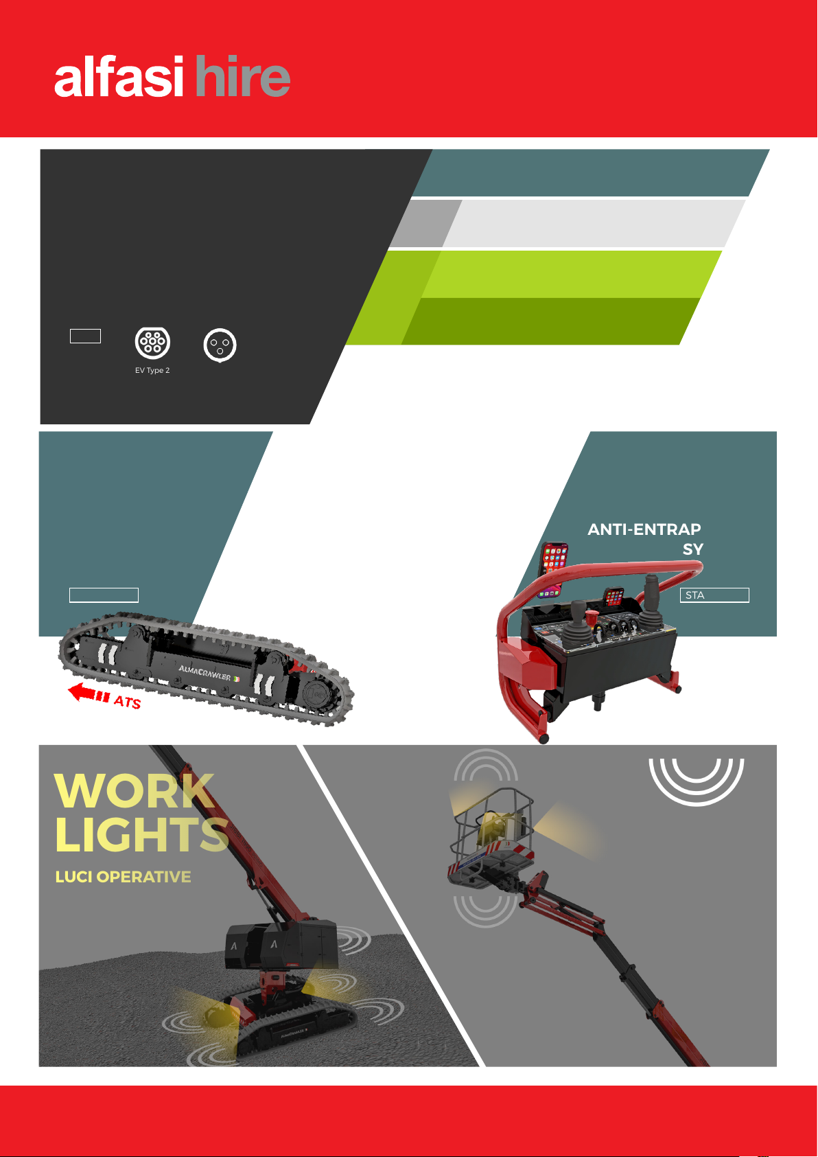
5.1.5 "AES" anti-entrapment operator kit..................................................................53
5.1.6 Pot-hole and anti-collision turret kit (OPTIONAL).................................................54
5.1.6.1 Pot-hole kit (OPTIONAL)................................................................................................ 55
5.1.6.2 Turret anti-collision kit................................................................................................. 55
5.2 CONTROL STATION ON THE GROUND. ..........................................................................57
5.2.1 Main key switch / control station selector. ........................................................58
5.2.2 Command enable button "ON" and command enabled green indicator light. .................58
5.2.3 Emergency stop button. ...............................................................................58
5.2.4 Emergency Override Button with leaded protection..............................................59
5.2.5 Warning light............................................................................................59
5.2.6 “MODE” button..........................................................................................59
5.2.7 TURRET ROTATION/LEVELING buttons...............................................................60
5.2.8 TELESCOPIC EXTENSION/RETRACTION buttons. ....................................................60
5.2.9 BOOM UP/DOWN /TURRET LEVELLING buttons.....................................................60
5.2.10 JIB UP/DOWN buttons...............................................................................61
5.2.11 PLATFORM ROTATION buttons. ....................................................................61
5.2.12 PLATFORM LEVELLING buttons.....................................................................61
5.2.13 Circular display. .....................................................................................62
5.2.13.1 Main error messages..................................................................................................... 62
5.2.14 BATTERY CHARGER indicator light................................................................66
5.2.15 Movement and alarm buzzer.......................................................................66
5.2.16 Ground control station light. ......................................................................66
5.2.17 Programming and diagnostic connector. .........................................................66
5.3 ACCESS TO THE PLATFORM.....................................................................................67
5.4 STARTING THE MACHINE. ......................................................................................68
5.5 STOPPING THE MACHINE. ......................................................................................69
5.5.1 Normal shutdown. ......................................................................................69
5.5.2 Emergency stop. ........................................................................................69
5.6 END OF WORK. ................................................................................................69
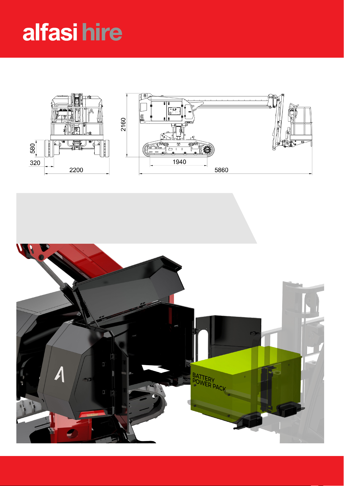
5.7 QUICK REPLACEMENT OF THE BATTERY PACK. .................................................................70
6LOADING AND TRANSPORT. .................................................................................. 71

PAGE 5
6.1 LOADING WITH LOADING RAMP.................................................................................71
6.2 LOADING WITH A FORKLIFT. ...................................................................................71
6.3 LOADING WITH A CRANE. ......................................................................................72
6.4 FIXING THE MACHINE ON THE MEANS OF TRANSPORT............................................................72
7EMERGENCY COMMANDS. ..................................................................................... 74
7.1.1 Emergency recovery of the incapacitated operator...............................................74
7.1.2 Emergency recovery of the incapacitated operator in the presence of an overload alarm. 75
7.1.3 Emergency recovery with a manual pump. .........................................................76
7.1.3.1 Operator emergency recovery......................................................................................... 76
8MAINTENANCE. ................................................................................................. 78
8.1 SAFETY RULES DURING MAINTENANCE. .........................................................................78
8.2 ORDINARY MAINTENANCE. .....................................................................................79
8.2.1 Cleaning the machine and adhesive plates. ........................................................80
8.2.2 Functional checks.......................................................................................80
8.2.3 Visual inspection of the structural elements of the machine. ..................................82
8.2.4 Visual check screw tightness / Screw tightening. .................................................83
8.2.5 Greasing joints, telescopic extensions and slewing ring..........................................84
8.2.6 Hydraulic oil level check / oil change...............................................................85
8.2.7 Hydraulic oil filter replacement. ....................................................................86
8.2.7.1 Delivery filters. .......................................................................................................... 86
8.2.7.2 Suction and return filters............................................................................................... 87
8.2.8 Traction reduction gear oil level check / oil change..............................................88
8.2.9 Tracks: check for wear, tensioning and replacement.............................................89
8.2.9.1 Track wear check........................................................................................................ 89
8.2.9.2 Track tension control and adjustment................................................................................ 89
8.2.9.3 Track replacement. ..................................................................................................... 89
8.2.10 Extension chains: Wear control, Tensioning and Lubrication. ................................91
8.2.10.1 Chain wear check........................................................................................................ 91
8.2.10.2 Chain tension control and adjustment................................................................................ 91
8.2.10.3 Chain lubrication. ....................................................................................................... 92
8.2.11 Check wear and register of sliding pads. ........................................................92
8.2.12 Turret rotation game control......................................................................93
8.2.13 Platform rotation game control...................................................................93
8.2.14 Overload control device check.....................................................................94
8.2.15 Machine sensor control. ............................................................................95
8.2.16 Ultrasonic sensor control of ANTI-COLLISION and ANTI-CRUSHING (optional)..............95
8.2.17 Ultrasonic sensor control of POT-HOLE and anti-collision turret (optional)................95
8.2.18 "AES" operator anti-entrapment system check. .................................................95
8.2.19 Battery. ...............................................................................................96
8.2.19.1 Battery of the control circuit.......................................................................................... 96
8.2.19.1.1 Maintenance of the control circuit battery. .................................................................... 96
8.2.19.1.2 Charging the battery of the control circuit. .................................................................... 96
8.2.19.2 LITHIUM battery (LTH versions)........................................................................................ 97
8.2.19.2.1 Maintenance of the LITHIUM battery (LTH versions)........................................................... 97
8.2.19.2.2 LITHIUM battery charging (LTH versions)........................................................................ 98
8.2.19.3 TRACTION battery (ELC versions). ...................................................................................100
8.2.19.3.1 TRACTION battery maintenance (ELC versions). ..............................................................100
8.2.19.3.2 TRACTION battery charging (ELC versions).....................................................................102
9DEMOLITION....................................................................................................103
9.1 MACHINE LIFE. .............................................................................................. 103
9.2 DECOMMISSIONING AND DEMOLITION. ........................................................................ 103
9.3 BATTERY DISPOSAL. ......................................................................................... 103
10 CE DECLARATION OF CONFORMITY (FAC-SIMILE). ......................................................104
11 CONTROL REGISTER. .........................................................................................105
11.1 REGISTER OF PERIODIC INSPECTIONS AND CHECKS BY THE CONTROL BODIES. .......................... 106
11.2 REGISTER OF PERIODIC INSPECTIONS BY THE OWNER..................................................... 107

PAGE 6
11.3 TRANSFERS OF OWNERSHIP. ................................................................................. 115
12 FUNCTIONAL DIAGRAMS. ....................................................................................116
12.1 WIRING DIAGRAMS........................................................................................ 116
12.2 HYDRAULIC DIAGRAMS................................................................................... 116

PAGE 7
1GENERAL INFORMATION.
This document contains proprietary information. All rights reserved.
This document cannot be reproduced, in whole or in part, without the prior written consent of ALMAC
s.r.l.
The use of this document is permitted only to the customer to whom the manual was provided as a kit
with the equipment, and only for purposes of use and maintenance of the equipment to which the manual
refers.
ALMAC s.r.l. declares that the information contained in this manual is consistent with the technical and
safety specifications of the equipment to which the manual refers. ALMAC s.r.l. assumes no responsibility
for direct or indirect damage to people, things or animals resulting from the use of the equipment in
conditions other than those provided.
ALMAC s.r.l. reserves the right to make changes or improvements without notice to this document and to
the equipment, without any obligation to update equipment already sent.
The information contained in this manual refers to the various equipment mentioned on the cover; some
images and / or information may not be specific to the set-up in the customer's possession because they
are not available or available on request.
1.1 Regulatory and legal aspects.
1.1.1 Documentation supplied.
The machine is delivered complete with the following documentation:
-Instruction manual (this document) including the Control Register;
-Spare parts manual;
-EC mark applied to the machine;
-EC declaration of conformity;
-Hydraulic schematic;
-Wiring diagram.
The instruction manual and the attached documents are integral parts of the machine and a copy of
these, together with the certificates of the mandatory periodic checks, must be kept on the machine in
the appropriate box. The original documents must be kept in a dry and protected place; in case of change
of ownership these documents must always accompany the machine.
In case of loss or damage, a new copy must be requested, specifying the model and serial number of the
machine.
1.1.2 Notification of commissioning, first check, subsequent periodic checks and
transfer of ownership.
The legal obligations of the owner of the machine differ according to the state in which the machine is
put into service. It is advisable to inquire about the procedures envisaged in your area at the bodies for
the protection of safety in the workplace. In order to improve the filing of documents and to record the
modification / assistance work, a section has been provided at the end of this booklet called "Control
Register".

PAGE 8
1.1.2.1Notification of commissioning and first check (only for Italy).
In Italy, the owner of the Elevating Work Platform (PLE) must report its commissioning to INAIL and submit
it to mandatory periodic checks. The first check is carried out by INAIL within sixty days from the request,
after which the employer can make use of the ASLs or authorized public or private entities.
Subsequent checks are carried out by the aforementioned subjects, who provide them within thirty days
from the request, after which the employer can make use of authorized public or private subjects. The
checks are expensive and the costs for their execution are borne by the owner of the machine. To carry
out the checks, the territorial supervisory bodies (ASL / USL or ARPA) and INAIL may avail themselves of
the support of authorized public or private entities. Authorized private entities acquire the qualification
of public service officers and report directly to the public structure that holds the function.
To report commissioning in Italy, it is necessary to connect to the INAIL portal following the instructions
on the portal itself.
INAIL will assign a serial number and during the First Inspection, will fill in the "technical identification
sheet", reporting on it only the data detectable by the machine already in service or inferable from the
instruction manual. This document will be an integral part of the machine documentation.
1.1.2.2Periodic checks following the first check.
In Italy, compulsory periodic checks take place annually. For their performance, it is necessary that the
owner of the PLE makes a request by registered letter to the supervisory body (ASL / USL or ARPA or other
authorized public or private subjects) competent for the territory at least twenty days before the end of
the year from the time of past verification.
It should be noted that, if a machine without a valid verification document is moved on the territory in
an area outside the competence of the usual supervisory body, it is the owner's obligation to request the
annual check from the supervisory body competent for the new territory. in which the machine is to
operate.
1.1.2.3Transfers of ownership of the PLE.
In Italy, in case of transfer of ownership, the previous owner of the PLE is required to communicate the
unavailability of the machine by connecting to the INAIL portal.
The new owner will have to retrieve the registration data of the PLE on the same INAIL portal, in order
to continue to subject the machine to the periodic checks required by law.
The new owner must in any case obtain from the previous owner the accompanying documentation
already mentioned in the previous chapters (see SUPPLIED DOCUMENTATION).
To take advantage of the WARRANTY and to receive any updates and SERVICE BULLETINS, the new owner
must report to ALMAC SRL that he has taken possession of the machine by means of written
communication using the forms provided at the end of this manual.

PAGE 9
1.1.3 Training, information and training of operators.
Training, information and training of operators are legal obligations for the employer. The employer must
in fact ensure that the workers in charge of the use of the equipment receive adequate and specific
training to allow their use in a suitable and safe way, also in relation to the damage that may be caused
to other people and things. Remember that both the one who directly manoeuvres the machine and the
one on the ground for any recovery and rescue operations are considered operators.
The operators in charge must be at least 18 years old and be recognized as suitable from a psycho-physical
point of view for this task. In particular, before driving, it is necessary to check the following
requirements:
-Sight and hearing in good condition;
-Absence of alterations induced by the use of alcohol or drugs;
-Psychological balance, absence of depression or stress.
1.1.4 Tests are carried out before delivery.
Before being placed on the market, each example of the ALMAC platform was subjected to the following
tests:
Braking test
Overload test
Function test
1.1.5 Warranty, Request for intervention under warranty and technical assistance.
1.1.5.1Warranty and disclaimer.
ALMAC S.r.l. guarantees the devices of its own production and undertakes to replace, free of charge, in
the shortest time possible, those parts that in its opinion are found to be defective.
Any intervention under warranty can only be carried out by ALMAC s.r.l or Almac s.r.l authorised personnel
and on the condition that the Customer is up to date with the payments.
The warranty is not recognized if the customer does not deliver the appliance for repair within 30 days
from the date of the first complaint to be made in writing.
With the exception of cases of wilful misconduct or gross negligence, any liability of ALMAC S.r.l. to the
Customer is excluded. for any damage resulting from faults/defects in the devices sold.
ALMAC S.r.l. is relieved of any liability and the warranty is void in the following cases:
-Use not permitted or not intended by this manual;
-Improper use of the machine or its use by unauthorised and / or untrained personnel;
-Use that does not comply with specific regulations;
-Lack of maintenance and / or not on time;
-Removal of seals;
-Modifications have been made to the machine without the prior written authorisation of ALMAC
S.r.l.;
-Non-genuine spare parts or spare parts not approved by ALMAC s.r.l. are used.

PAGE 10
1.1.5.2Request for intervention under warranty and technical assistance.
Any requests for spare parts or technical interventions under warranty must be reported to ALMAC S.r.l.
as soon as a defect is found.
For any request for assistance, always contact the ALMAC technical assistance service as indicated below:
Always indicate the type and the serial number of the machine when requesting spare parts under
warranty or technical interventions. These data are indicated on the machine identification plate.
REGISTERED OFFICE OPERATIONAL
HEADQUARTERS
ALMAC S.r.l.
Viale Ruggeri 6 / A
42016 Guastalla (RE) Italy
ALMAC S.r.l.
Via Caduti sul lavoro 1
46019 Viadana (MN)
Phone +39 0375 833527
Fax. +39 0375 784350
Email: info@almac-italia.com

PAGE 11
1.2 Description and intended use of the machine.
The machine described in this manual is a self-propelled Elevating Work Platform or, as described by the
EN280 technical standard, a mobile machine designed to move people to work positions, in which they
perform tasks while remaining on the work platform, with the understanding that persons enter and exit
the work platform only through access positions at ground or chassis level, and which consists of at least
a work platform with controls, an extendable structure (lift arms) and a frame.
The planned activities are:
-Green maintenance;
-Maintenance and installation of systems or devices at height;
-Cleaning;
-Stripping, sandblasting, painting, welding (carefully protecting the machine and its devices);
-All the activities to be carried out at height with the operator on the platform;
The maximum capacity allowed (different for each model; refer to the technical data in the tables later
in this manual) consists of:
-For each person a load of 80 kg is considered;
-For the equipment, a minimum load of 40 kg is considered;
-The remaining load is represented by the material being processed.
The machine essentially consists of:
-A motorized undercarriage, with fixed track, equipped with crawlers.
-Hydraulically rotating turret;
-Extensible structure operated by hydraulic cylinders;
-Operator platform.
The base chassis is mainly composed of the following components:
-Fixed central frame on which the hydraulic control block for turret leveling and track
tensioning, and the undercarriage inclination sensor are installed;
-Left track equipped with electric gearmotor for moving the machine;
-Right track equipped with electric gearmotor for moving the machine;
-Articulated fifth wheel support that is operated directly by a pair of hydraulic cylinders for the
levelling control of the superstructure, on which the rotation fifth wheel is fixed.
The turret supports the power source (battery, inverters, electric pump) and all the components of the
control circuits (oil tank, hydraulic block, electronic control units, ground control station). It rotates
hydraulically and is fixed to the articulated support of the chassis. It allows rotation of the superstructure
with respect to the vertical axis of the machine. The allowed rotation is limited, and this limitation varies
from model to model (see the technical data table to understand the maximum rotation angle of each
model).
The extensible structure consists of
oTelescopic main arm;
oJib
The lifting / lowering movements of the arm and the jib are carried out by means of hydraulic cylinders
equipped with over-centre valves directly flanged on them in order to keep the arms in position even in
the event of accidental breakage of a supply pipe.
The telescopic extension is operated by a double-acting hydraulic cylinder with over-centre valve and by
a Fleyer chain system.
The work platform is fixed to the end of the jib arm and can be rotated differently for each model (see
the technical data table to understand the maximum rotation angle of each model) by means of a rotary
actuator also provided of the over-centre valve to keep it in position in case of hydraulic failure. The
platform is made of aluminium and is equipped with safety rails and toe-boards of regular height (Safety
rails H = 1100 mm; toeboard H = 150 mm). Platforms of various sizes can be installed; see technical data.
The levelling of the platform is automatic and is provided by an electronic automatic leveling system.
For transport needs, it is possible to reduce the overall length of the machine by removing the platform.
This operation is reserved to ALMAC authorized technicians and requires the use of tools.
The machine control system consists of several sensors that allow you to keep overall stability under
control by keeping the turret and the extensible structure level and adjusting the height, outreach and
working speed according to the various monitored parameters, i.e.:

PAGE 12
-Ground inclination;
-Opening angle of the main arm;
-Position of the telescopic extension of the arm;
-Opening angle of the jib;
-Loading on the platform.
By means of the display at the ground control station and the LED indicators on the control panel in the
platform, the operator on board is constantly informed of the operating limits reached and the
movements allowed.

PAGE 13
1.3 Operating positions.
The normal operating position is on the platform, whereas there is a control station on the ground for
platform emergency recovery, emergency stop, maintenance, and machine on/off.
1.3.1 Foot-driven use (function reserved for ALMAC authorized technicians).
It is possible, by means of an additional control console (provided to ALMAC authorised technicians only)
to drive the machine by walking operator, during loading/unloading operations of the machine from
containers or closed means of transport where it is necessary to remove the platform beforehand.
A limited number of movements are allowed using the additional control console, for the only purpose of
loading/unloading the machine.
This feature is not available to the operator for standard use.
1.4 Power.
The machine is equipped with an electrical and hydraulic system through which the movement is
obtained. The drive is controlled by a pair of electric gearmotors.
The machines can be set up with different energy sources based on the following:
-ELC version = Machine powered by lead-acid battery and electric pump;
-LTH version = Machine powered by lithium battery and electric pump;
The battery pack is easily interchangeable, and either the lithium battery or the lead-acid battery can
be installed, following the instructions in this manual.
In any case, both the hydraulic and electrical systems are equipped with all the necessary protections
(see electrical and hydraulic diagrams supplied as attachments to this manual).
1.5 Uses not permitted and "Exiting the platform at height".
Normal and permitted use of the machine is described in the previous paragraphs. Anything not described
as normal and permitted use is to be considered as not permitted use.
-It is forbidden to operate the work platform from the ground control station except for
emergency recovery operations and maintenance activities.
-It is forbidden to operate the work platform by means of additional control console (optional)
outside of loading/unloading operations.
-Since the MEWPs are designed to operate from the operating position on the platform, and the
only permitted access position is the one that foresees the platform on the ground, any activity
that involves accessing and / or exiting with the platform in a position other than that of access
(the so-called "landing at height") is formally prohibited.

PAGE 14
1.6 Identification.
In the event of a request for spare parts and for interventions, the data shown on the registration plate
located on the turret or on the identification plate on the platform must always be mentioned. In case
of loss or illegibility of the plates (as well as for the various adhesive plates located throughout the
machine), it must be restored as quickly as possible.
For the location of the plates see the following figure. It is advisable to transcribe these data in the
following table:
MODEL:______________
SERIAL NUMBER: ______________
YEAR: __________________
Figure1
This manual suits for next models
1
Table of contents
Other ALMACRAWLER Boom Lift manuals
Popular Boom Lift manuals by other brands

JLG
JLG GRADALL 544D Owner's/operator's manual

Terex
Terex S65XCM-101 Service and repair manual

Haulotte
Haulotte OPTIMUM 1931 E Operator's manual

Oshkosh Corporation
Oshkosh Corporation JLG E400Anarrow Service and maintenance manual

Haulotte
Haulotte HA32RTJ PRO Maintenance book

Terex
Terex Genie Z-60 DC Operator's manual

Upright
Upright TL49K Operator's manual

Oshkosh
Oshkosh JLG 400S Service and maintenance manual

Sinoboom
Sinoboom TB14J Plus Operation manual

Upright
Upright TL50 Service & parts manual

Oshkosh Corporation
Oshkosh Corporation JLG H800AJ Service and maintenance manual

Terex
Terex Genie S-60 FE Operator's manual