Almeco ACI EP10A Manual

www.almeco.eu
DRYING SYSTEMS
EP10A Compact blower
Installation-, operation & maintenance
Instruction manual
EP10A compact blower

ALMECO nv Air and water technologies
Royennestraat 51, B-7700 Moeskroen
EP10A compact blower
TABLE OF CONTENTS
1. Key points for maintaining the EP10A Compact Blower 3
2. General EP10A Compact Blower information 4
a. Description and model identication
b. Equipment arrival
3. Key features and dimensions 5
a. Key EP10A features
b. Key EP10AH features
c. Illustration - further EP10A key features
4. Installation/ operation instruction 8
a. General safety procedures
b. Mounting
c. Location
d. Blower connections
e. Electrical connections
f. Shaft rotation
5. Maintenance instructions 10
6. Troubleshooting 14
7. Warranty & service exchange 16

ALMECO nv Air and water technologies
Royennestraat 51, B-7700 Moeskroen
3
!
EP10A compact blower
1. KEY POINTS FOR MAINTAINING THE EP10A COMPACT BLOWER
Health and safety
• Never operate the blower without a belt guard tted or without the inlet lter/ ducting tted to the blower inlet.
• The blower incorporates high speed moving parts that can cause injury.
Electrical
• Ensure that any ducting and equipment tted to the discharge has a suitable resistance to ensure the motor does not
draw too much current.
• Only use a suitable starter with overload protection.
• Soft start starters are recommended. Direct on line starting is not recommended.
• If using a frequency inverter or soft starter then ensure ramp up and down times are at least 5 seconds.
• Check the direction of rotation. PLEASE NOTE: if the rotation is incorrect, air will continue to ow out of the
discharge, but at approximately 60% of normal performance.
Control
• The units are designed to run continuously. Avoid frequent stop starts - we recommend no more than 6 per hour
unless used with an inverter or soft start. Soft start overruns should be 2 ½ minutes.
• If the blower control is linked to other equipment then ensure that this does not go above the recommended
number of starts and stops, if so then use a timer delay in the control to avoid frequent switching.
• The EP10A blower needs to have airow passing through it to ensure temperatures are not exceeded. The use of
control valves should be limited to ensure that at least 150 CFM passes through the head at all times.
• Avoid using fast-acting valves and diverter valves in the ducting. This can cause sudden back pressure changes.
Siting
• Mounting - ensure the blower is isolated from vibration.
• Allow for access to the belt guard for maintenance and for movement of the head for adjustment of the belt.
• Ensure adequate ventilation of motor. If the blower is tted into an acoustic enclosure, adequate ventilation must be
provided to ensure the internal enclosure temperature does not exceed 50ºC / 122ºF.
• During operation, avoid moisture or debris entering the blower, keep in a clean and dry area.
Critical maintenance
• Keep lter clean – Almeco recommend cleaning every month depending on the working environment. The
maximum lter element life is 6 months.
• Only lters and belts supplied by Almeco or its distributors should be tted to the EP10A/EP10AH Blower.
• Belt tension should be checked regularly (Once per 500 working hours).
• Keep the motor clean (once per month) and free from dust build up.
• Check regularly for excessive noise and vibration.
Use and operation of the EP10A blower contrary to these conditions state above will
immediately invalidate any warranty agreement

ALMECO nv Air and water technologies
Royennestraat 51, B-7700 Moeskroen
4
!
EP10A compact blower
2. GENERAL EP10A COMPACT BLOWER INFORMATION
All service procedures and electrical work should only be performed by trained personnel. Please read the following
installation, operation and maintenance instructions carefully.
a. Description and model identication
Almeco’s EP10A blower is an industrial type variable speed centrifugal unit capable of producing high velocity hot and
cold air. The unit is available as a standard version (EP10A) for handling air in normal ambient conditions, or as a hot–
air version (EP10AH) where air temperatures of up to 365 ºF (185 ºC) can be processed.
Almeco clearly labels each EP10A/EP10AH blower unit on the back of the blower head, as well as the motor cowl label
(See below). The serial number is located on this label.
Figure 1: Typical Motor label
b. Equipment arrival
• Important information
Please read the following installation, operation and maintenance instructions carefully. Always ensure that the
power is isolated before commencing any maintenance on the EP10A/EP10AH unit.
• Equipment arrival/inspection
If there are any shortages, discrepancies or damage to your product upon delivery of your EP10A /EP10AH unit,
please immediately contact Almeco.
Always ensure that the power is isolated and locked o before commencing any maintenance on the
EP10A blower unit.

ALMECO nv Air and water technologies
Royennestraat 51, B-7700 Moeskroen
5
EP10A compact blower
3. KEY FEATURES AND DIMENSIONS
a. Key EP10A features
If the head is returned
to Almeco for refurbishment, it
must be complete, otherwise
the warranty will be void
Complete EP10A Head Assembly [Ref: B3.003.037] Filter Assembly [Ref: ACKB-233/PRE & ACKB-234]
The pre-lter should be
cleaned regularly and the
main element replaced
every six months
Drive belt guard
Poly V-belt
Motor pulley
Motor IE3
Blowerhead EP10 A
Filter
[Ref: B3.003.039]
B3.000.185
Prefilter
B3.000.147
Polyester filterelement
B3.003.031
Ø1194 | 20.000T
B3.003.030
Ø1143 | 18.000T
B3.003.029
Ø1105 | 16.000T
B3.003.028
Ø1054 | 14.000T
B3.003.027
Ø991 | 12.000T
B3.003.026
Ø260 | 20.000T
B3.003.024
Ø234 | 18.000T
B3.003.022
Ø208 | 16.000T
B3.003.020
Ø182 | 14.000T
B3.003.018
Ø156 | 12.000T
B3.003.034
5.5 kW
B3.003.035
7,5 kW
B3.003.036
11 kW
B3.001.859
15 kW
B3.003.037
Blowerhead
B3.002.687
Blowerhead reviewed

ALMECO nv Air and water technologies
Royennestraat 51, B-7700 Moeskroen
Ref: B3.003.037
Thermal cut Hot air
Ref: ACEP-250H
7
EP10A compact blower
c. Illustration - further EP10A Key Features
d. EP10A Head Options:
Electric Motor - Standard
Metric or NEMA
Filter Assembly
Belt Tensioning Stud
EP10A Blower Discharge
Krikit Tension Gauge
Drive Belt
Belt Guard

ALMECO nv Air and water technologies
Royennestraat 51, B-7700 Moeskroen
8
EP10A compact blower
4. INSTALLATION/ OPERATION INSTRUCTIONS
a. General Safety Procedures
• Ensure all safety instructions are fully understood by the personnel undertaking the work and that those personnel
are familiar with any emergency apparatus.
• Only qualied electrical and competent mechanical personnel should be used for installation and maintenance
procedures for the EP10A/EP10AH units.
• Before any installation or maintenance work is carried out, ensure all electrical connections are disconnected from
the motor starter, fuse box, or circuit breaker and check that the power cannot be switched on.
• IEE and other relevant regulations should be observed when installing the unit.
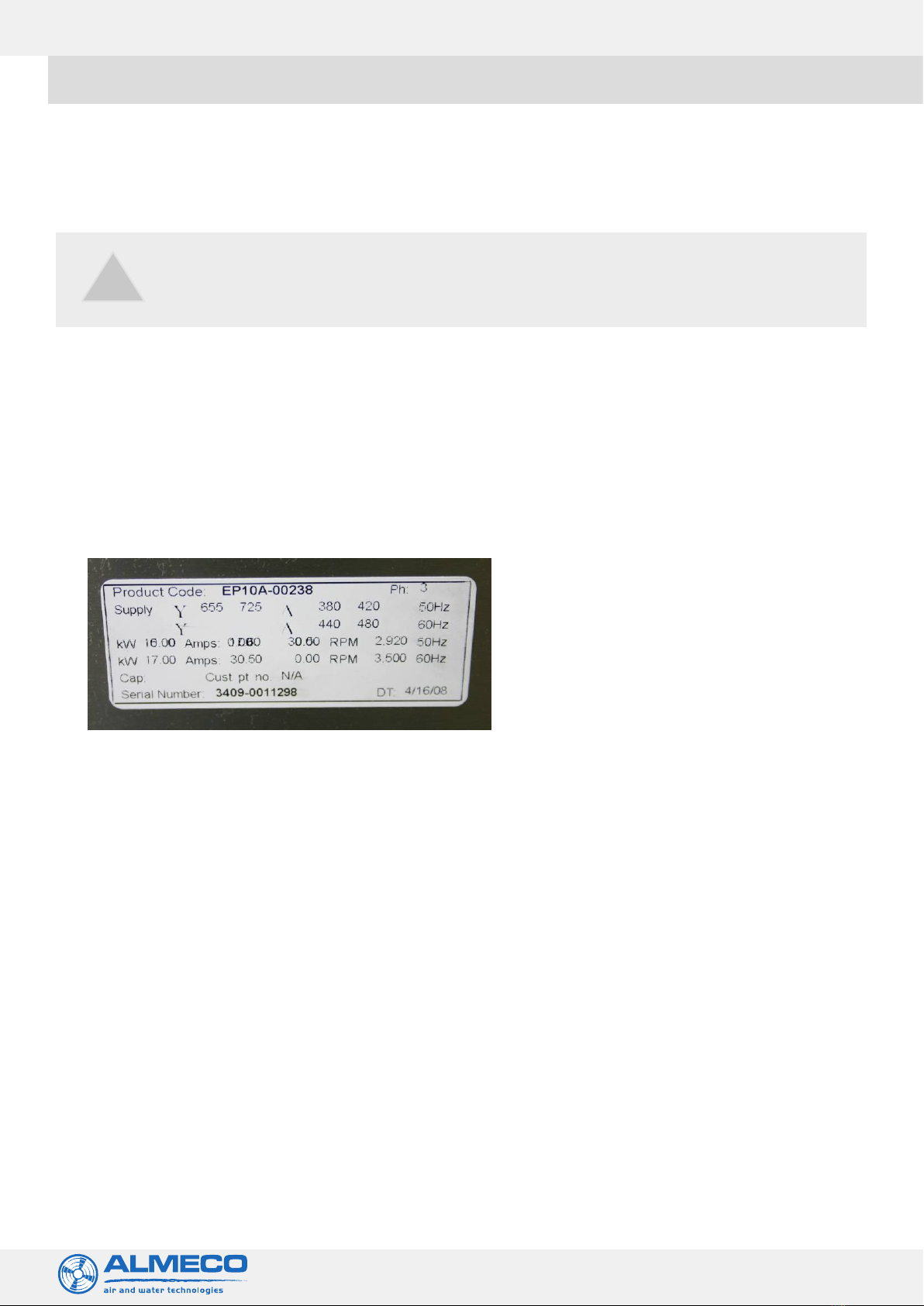
• For correct power supply requirements; please refer to the motor nameplate.
When operating this unit, please ensure good safety practices are followed. For example:
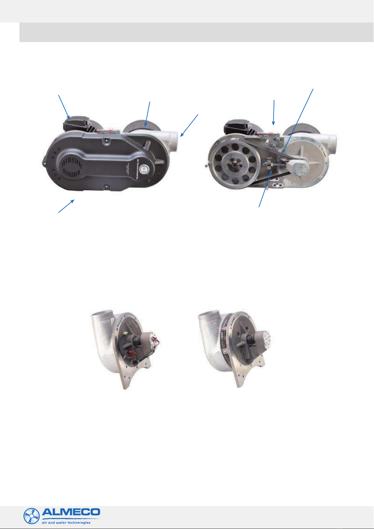
1. Ensure that the belt guard is tted.
2. The unit is not operating independently of the system without securely blanking o the outlet or inlet.
3. All tools, clothing and hands should be kept away from rotating or moving parts.
4. Ensure adequate eye, ear and foot protection is worn.
5. Lifting equipment is used to move the blower into position. When lifting please ensure that the blower is secure and
do not use the blower’s inlet spigot as a lifting point.
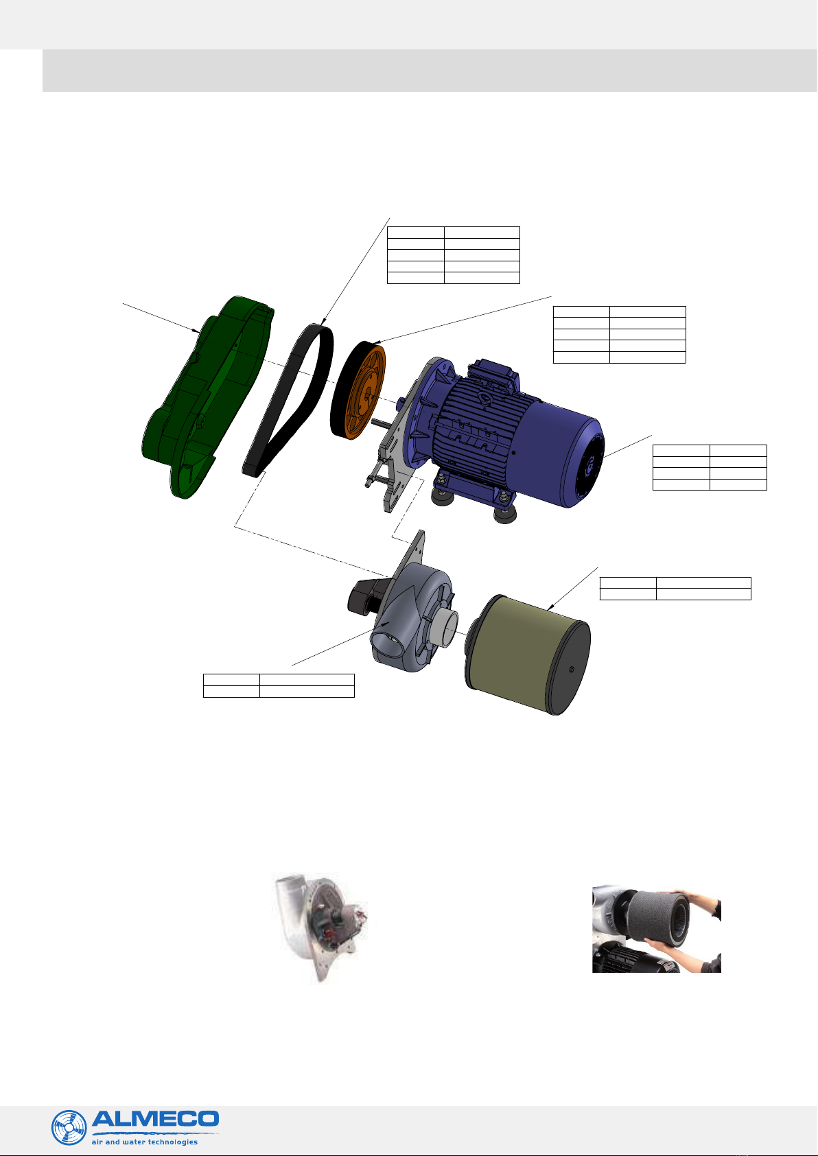
b. Mounting
Units are normally supplied free standing from the motor mounting feet. The EP10A/EP10AH blower head is belt driven
and normally mounted from the large ange of a standard metric motor.
NEMA frame motors can be used with the blower and a special motor mounting plate is provided to suit the large ‘C face’
conguration.
NOTE: Allow room for bracket movement during belt replacement. Very low vibration levels of these units allow them
to be bolted to any type of foundation or framework without signicant eect. Vibration isolation mounts are
recommended if other motor driven equipment is to be mounted to the same structure.
c. Location
The unit assembly must be suitably located to allow access for drive belt and lter replacement. Ambient temperature
conditions should range from -10ºC to + 50ºC (14ºF to 122ºF) and adequate ventilation provided for the motor. In factory
locations subject to high-pressure water or caustic wash-down cycles, protect or relocate the blower to prevent damage.
If the unit has been supplied with an acoustic enclosure, an internal enclosure temperature of + 50ºC (122ºF) must not be
exceeded.
d. Blower connections
The unit is supplied with an inlet lter and discharge connection, suitable for attaching exible hose. Spigots are
Ø100mm. It is recommended that the unit discharge be coupled to system piping via a short length of flexible hose and
directed away from personnel and silenced to reduce noise levels to within occupational safety standards.
Flexible hose can introduce a high-pressure drop and lengths should therefore be kept to a minimum. The inlet filter
must not be removed, re-circulating systems are not recommended and any deviation from standard use as a blower
must be approved by Almeco. Recommended inlet air temperature is less than 50°C/122°F. The blower is designed to give
a continuous, stable supply of pressurised air and should not be subjected to frequent or large changes in back-pressure
from shut-off or diverted valves other than advised by Almeco. The blower should not be operated until it has been fully
connected to the complete system it will be operating.

ALMECO nv Air and water technologies
Royennestraat 51, B-7700 Moeskroen
9
EP10A compact blower
e. Electrical connections
Units are typically driven by a metric frame electric motor with an environmental protection level IP55. If alternative
motors are supplied, reference to the motor rating plate is required for all electrical details. The blower is designed to be
continuously run at its designated speed, any inverter drive program giving speed control and/ or speed changes must be
approved by Almeco.
If a star/ delta starter has not been supplied with the unit, it is not Almeco’s responsibility to control the starting of the
unit.
I. We recommend that a soft start with thermistor control is used to start the blower, or an inverter with ramp-up
and down time set at 5 seconds.
II. If star/delta starting is used and switched by a plc, it is the customer’s responsibility to ensure that the switching
times are correct. In this case the number of start/stops is limited to 6 per hour.
III. All wiring should be installed to national wiring standards.
Table 1: Motor conguration options:
a. Delta conguration b. Star conguration c. Star/ delta starter
If an inverter is not used, use a suitable
starter with overload protection star/
delta starter.
f. Shaft rotation
All units rotate counter clockwise when viewing the blower from the cooling fan of the motor. Alternatively, clockwise
when viewing the polley/ shaft end.
NOTE (a): Air will ow out of the blower discharge even when it is run in reverse but at approximately 60% of the normal
performance.
NOTE (b):
• Never run the blower unit without the belt and belt guard tted.
• Never run the blower when disconnected from ducting/ air delivery device.
• Always ensure that the power is isolated and locked o before commencing any maintenance on the unit.
• Before operating the blower ensure that the blower is secured in position.
All blower motors are supplied with a thermistor connection. It is important to use these as it protects the motor and
may prevent the motor/blower from failure. All Almeco starters provide this safety cut-out feature. As an optional extra
the blower head can come equipped with two thermal cut-out probes which provide the blower head bearings with
additional protection. These probes will be pre-wired into the motor thermistor circuit and are wired into terminals T1 and
T2 as shown in Figure 4.
!
!
Ramp-up and down times should be set at no less than 5 seconds.
Incorrect fan rotation is the most common cause of drying system under
performance. Double check!

ALMECO nv Air and water technologies
Royennestraat 51, B-7700 Moeskroen
10
EP10A compact blower
Main lter element cleaning/ Replacement procedures
Image: Wiring diagram for Soft Start
5. MAINTENANCE INSTRUCTIONS
a. Filters
Almeco’s EP10A/EP10AH blower units are designed to be a minimum maintenance device. However, the execution of a
few basic maintenance functions will extend the life of the mechanical components and ensure continued eciency and
longevity.
Removing lter element
Step 1: Remove pre-lter element by
releasing the security nut and washer.
Use a 17mm AF spanner.
Step 2: Withdraw the lter end-plate
and lter assembly over the xing stud.
Step 3: Remove the pre-lter sock from
the main lter element.
Step 1: Place the pre-lter sock in warm water,
preferably with a low foaming detergent.
Step 2: Wash pre-lter sock thoroughly.
Rinse through thoroughly in clean water
and squeeze as much water out as possible.
Leave to dry thoroughly before replacing.

ALMECO nv Air and water technologies
Royennestraat 51, B-7700 Moeskroen
11
EP10A compact blower
!The main lter element must be dried o completely otherwise moisture will be
drawn through the blower head which could possibly cause a major and costly
failure.
It is essential that air lters are regularly maintained and replaced.
!
• Replacement procedure: the main lter element will need replacing every six months. This and other items can be
ordered directly from Almeco.
• Cleaning procedure: the main filter element may be washed using the same procedure as the pre-filter sock. It is
important to be aware that the cleaning procedure for this part is far more time consuming and because of this, we
recommend a spare filter is fitted whilst the cleaning procedure is carried out.
Once the main filter element has been washed and rinsed, we recommend the following:
• Remove as much of the water soaked up by the main filter element.
• It is then suggested that the filter is placed in an oven at 60°C for a minimum of 4 hours. If an oven is not available, dry
off in a well ventilated room and leave for 24 hours minimum - longer if the unit is still not dry.
Re-tting lter elements:
• Once the main filter element and the pre-filter sock are thoroughly dried, they can be re-fitted to each other.
• Refit the filter and its cover and secure in place using the nut and washer.
Drive Belts
• Checking tension using the supplied Krikit Tension Gauge (The Krikit II belt tension gauge, with the brightly coloured
pressure pad and indicator arm, is calibrated to measure Micro-V belt tensions).
• Place the gauge in the centre of the belt and align the sides of the gauge to the edges of the belt and midway
between any two pulleys (refer to images below). The belt tension accuracy is dependent on this
• procedure.
• Push slowly on the coloured pad to get an accurate reading. When you hear the “click”, immediately stop pressing and
remove the gauge carefully, so as not to move the indicator arm.
• Turn the gauge sideways to see the exact spot where the top of the indicator arm intersects the scale.
• Mark this spot with thumbnail and turn gauge to read the scale accurately.
• It is recommended that more than one tension reading be taken to assure repeatable measurements.
• Increase or decrease the belt tension until you are within the desired tension range. Almeco belt tension = see label
on unit – typically 50Kg or 110lbs.
Drive belts will need to be checked every 500 working hours and replaced every 2
years.
!

ALMECO nv Air and water technologies
Royennestraat 51, B-7700 Moeskroen
12
EP10A compact blower
!
Image: EP10A Tension Gauge (ref: Krikit Gauge)
To remove a drive belt
• Isolate the power supply.
• Remove the belt guard.
• Disconnect any ducting.
• Loosen the 4 off M10 bolts clamping the motor mounting plate to the blower back plate, using a 17mm spanner or
socket.
• Slacken the 2 off M12 nuts on adjustment screw above and below adjustment anchor cast into motor mounting
plate, slacken top nut using a 19mm spanner, to allow the blower head/back plate assembly to drop sufficiently to
facilitate the removal of the belt.
• After removal ensure the pulleys are clear of any dust or debris. If the belt is to be re-used wipe with a dry cloth before
attempting to refit.
To ret a drive belt
• Fit the new belt over the pulleys ensuring that it is correctly aligned with the poly-vee pulleys. Do not force the belt or
roll the belt onto the pulleys. Ensure the blower head is low enough to allow the belt to clear before attempting to fit.
• Using the M12 nuts on the adjusting screw, apply sufficient tension to raise the blower head/back plate assembly into
its approximate position and lightly tighten the M10 bolts to hold the assembly in place.
• Tension using the M12 nut on the upper side of the adjustment anchor checking the tension with ‘Krikit’ tension
gauge supplied. (Refer to figures 4 & 5). When the correct tension is achieved (50kg or110lbs on the scale), lock
adjuster by tightening the M12 nut on the underside of the adjustment anchor and tighten M10 bolts to approx.
20N/M.
• After fitting a new belt, the tension should be re-checked after the unit has been run between 10-20 minutes. This is
due to initial stretch of a new belt.
• Only drive belts supplied by Almeco should be used.
Blower heads
The EP10A’s head assembly comprises:
a. fan case
b. inlet ring
c. back plate
d. impeller
e. spindle assembly
When replacing this compact blower head, the pulley and hub position must be checked. [Please note - This blower head
is a newer design with a different pulley position to older units supplied pre 2002.]
For standard metric frame motors the hub that the pulley mounts on must be 20-21mm from the motor flange face. If it is
a NEMA motor this dimension must be 14-15mm.
Drive belts supplied by Almeco should be used.

ALMECO nv Air and water technologies
Royennestraat 51, B-7700 Moeskroen
13
EP10A compact blower
• To change the position, remove the three cap-head crews that secure the pulley to the hub and remove the pulley.
Mark the position of the hub to ensure this is replaced in the same position.
• Release the hub by undoing the two cap-head screws and the one grub-screw that locks the key in position.
• The hub can now be positioned along the shaft to the new dimension. You may need to tap it with a soft faced mallet.
• Re-tighten the grub-screw and cap-head screws. Re-mount and secure the pulley.
• After fitting the head, the pulley alignment can be checked by using a long straight edge.
• All nuts to be new ‘Nyloc’ or loctite to be applied.
To remove the blower head
• Isolate the power supply.
• Remove the belt guard.
• Disconnect any ducting.
• Loosen the 4 off M10 bolts clamping the motor mounting plate to the blower back plate, using a 17mm spanner or
socket.
• Slacken the 2 off M12 nuts on adjustment screw above and below adjustment anchor cast into motor mounting
plate, slacken top nut using a 19mm spanner, to allow the blower head/back plate assembly to drop sufficiently to
facilitate the removal of the belt.
• After removal ensure the pulleys are clear of any dust or debris. If the belt is to be re-used wipe with a dry cloth before
attempting to refit.
• Once the belt is removed the four M10 clamping bolts can be fully withdrawn from the motor mounting plate. This
will allow the head to become detached.
• Remove the M12 belt tensioning stud from the used head with a 19mm spanner.
Retting a new head
• Fit the belt tensioning stud from the old head to the new head assembly
• Lift the blower head into position onto the motor mounting plate & ret the four M10 clamping bolts through the
motor mounting plate.
• Fit the new belt over the pulleys ensuring that it is correctly aligned with the poly-vee pulleys. Do not force the belt or
roll the belt onto the pulleys. Ensure the blower head is low enough to allow the belt to clear before attempting to t.
• Using the M12 nuts on the adjusting screw, apply sucient tension to raise the blower head/back plate assembly into
its approximate position and lightly tighten the M10 bolts to hold the assembly in place.
• Tension using the M12 nut on the upper side of the adjustment anchor checking the tension with ‘Krikit’ tension
gauge supplied. (Refer to gures 4 & 5). When the correct tension is achieved (50kg or110lbs on the scale), lock
adjuster by tightening the M12 nut on the underside of the adjustment anchor and tighten M10 bolts to approx.
20N/M.
• Ret the belt guard.
• Reconnect the blower ducting.
• The electrical supply should now be reconnected.
• After tting a new belt, the tension should be re-checked after the unit has been run between 10-20 minutes.
• This is due to initial stretch of a new belt.
• Only drive belts supplied by Almeco should be used.
Fitting an EP-250/T/SN (or EP-250HT) replacement head assembly on the EP10 in place of a nonthermal cut-out head.
• On receipt of the blower head you will have additional thermal cut-out’s as well as a control wire lead set. The thermal
cut-out head should be tted as per the standard head, please see section 3c for full details.
• To electrically t the thermal cut-out devices it is necessary to break into the motor thermistor circuit inside the motor
terminal box. Please follow the diagram shown overleaf.
• If an Almeco Soft Start or Star/Delta Starter is used, upon a trip from either the motor thermistor or the thermal cut-
out probes the blower will stop. Only upon turning the starter o and then on again (once the thermal cut-out has
cooled) can running of the blower then resume.
• If a non Almeco supplied starter is used it is vital that the blower will not restart automatically after the thermistor or
cut-out probe has cooled. In this case this is the customer’s responsibility.
• Please note that the motor thermistor must be used in order for Almeco to uphold its warranty.

ALMECO nv Air and water technologies
Royennestraat 51, B-7700 Moeskroen
14
EP10A compact blower
Wiring diagram: Thermal Cut-Outs
6. TROUBLESHOOTING
Malfunction Possible cause Remedy
Low ow/ pressure/ vacuum Incorrect blower rotation Check and correct lower rotation if required
Dirty or contaminated lters Failure to change lters - MUST be changed regularly,
dependant on amount of use but a minium of every six
months. Refer to
Section 5, Filter Maintenance
Damaged hose lining Replace damaged hose
Air leaks in system Check/ replace damaged hose and clips
Drive belt slipping/ Worn Pulley Replace transmission parts
Incorrect speed from control system Check inverter/ soft start/ star delta settings
Unapproved drive belts being tted Replace existing drive belt with Almeco approved belt
Closed or damaged valve Check valve and replace if damaged
High ow/ pressure Blower speed too high for application Reduce blower speed by using inverter or reducing
pulley size
Operating frequency too high - maximum
head speed must not exceed 20,000 rpm
Check design frequency and reduce by inverter or
change pulley size

ALMECO nv Air and water technologies
Royennestraat 51, B-7700 Moeskroen
15
EP10A compact blower
Malfunction Possible cause Remedy
Frequent drive belt failure Incorrect belt tension Check belt tension and correct if necessary. See section
5b
Motor pulley out of alignment Check pulley alignment and correct if necessary
Pulley grooves worn Replace transmission parts
Hostile environment (belts contaminated) Replace belt, clean pulleys and protect blower from
hostile environment
Incorrect belt tted Replace existing belt with Almeco approved belt
Incorrect belt installation method (Rolling
belts onto pulleys)
Read manual (Section 5b) for correct installation and do
not roll belts
Liquid entering blower inlet Avoid any liquid entering blower
Incorrect starting ramp The unit is designed to run CONTINUOUSLY. The start
and stop must be progressive; if an inverter is used we
recommend a 5 second ramp up time. If a star/ delta
timer is used ensure there is no delay between switch-
ing from star to delta
Too many stop/ starts Avoid high number of stop starts (max of 6 per hour)
unless using a frequency inverter or a soft start. Sug-
gested minimum inverter setting = 30Hz
Electrical overloading Exceeding rated CFM Reduce “open area”of air delivery devices - i.e. slot
width of Airknives
Blower not piped to system Only run blower when connected to the operating
system. Never run in isolation
Blower RPM too high Reduce blower speed via inverter or change pulley size
Motor has winding or bearing damage Contact Almeco immediately
Electrical supply problems Ensure that supply voltages match with the motor rat-
ing plate details
Irregular/ excessive noise Blockage in air delivery ducting Check all ducting and air delivery devices for block-
ages/ damage. Replace as necessary
Leak in air delivery ducting Check and replace damaged hose and clips.
Inlet silencer damaged (internally) Replace main EP10 lter housing. See Section 5
Loose drive belt Check belt tension and correct if necessary. See Section
5b
Bolts loose on blower/ motor assembly Regular maintenance and checking/ tightening all bolts
Motor mounts loose Regular maintenance and checking/ tightening all
mounts
Blower bearings worn Contact Almeco immediately
Motor bearings worn Contact Almeco immediately
Blower RPM too high Reduce blower speed via inverter or change pulley size
Blower is receiving vibration from other
equipment nearby
Isolate the blower using anti-vibration mounts
If you experience a problem and are in any doubt on the cause or possible remedial action required, please contact
your local distributor.

ALMECO nv Air and water technologies
Royennestraat 51, B-7700 Moeskroen
Almeco NV-SA
Air and Water Technologies
Royennestraat 51, B-7700 Moeskroen
Tel.: +32 (0)56 85 40 80 Fax: +32 (0)56 85 40 81
16
EP10A compact blower
7. WARRANTY & SERVICE EXCHANGE
Almeco warrants all products manufactured by ACI to be free of defects in material and workmanship for eighteen (18)
months from the date of shipment. The warranty does not apply to drive belts, lter elements or connecting hose, unless
authorised by an ocer of ACI. Also, not covered under the warranty is normal wear and tear, neglect or misuse of the
equipment, operation in an application not approved by Almeco and ACI, and alterations not performed by Almeco.
All items supplied by Almeco that are manufactured by others shall be warranted under the respective manufacturer’s
policy. Motors and other items, for which a national service network is in place, should be sent directly to that
manufacturer’s representative for the most prompt service. Almeco will provide any support required ensuring that
warranty service by others is handled in a prompt and professional manner.
The Almeco warranty is limited to the repair or replacement of items shipped by Almeco. At no time will Almeco be liable
for any of the costs to the buyer for labour, transportation or down-time resulting from defective equipment furnished by
ACI, Almeco or our suppliers.
To comply with the Warranty the complete fan unit must be returned to Almeco. Disassembly of the fan will invalidate the
warranty.
Service Address:
Our products are manufactured in compliance with applicable international standards and regulations. If you have any
queries regarding the use of our products, or if you are planning a special application, please contact:
ALMECO nv Air and water technologies
Royennestraat 51, B-7700 Moeskroen
This manual suits for next models
1
Table of contents