IL521
Section A
PreliminaryRev.5-11/97
APARTMENT INTERCOM ENTRANCE PANELS
WITH PK292A AMPLIFIER
2. Do not apply power to transformer primary until entire system has
been installed and connected.
3. Use twisted pair wiring and shielded wiring where shown.
TEST AND CHECKOUT
1. At the entrance panel, press each button, checking to see that the
correct suite is buzzed each time.
2. At each suite, pick up the phone and communicate with someone at
the entrance panel, then press door button to check door release
operation.
ADJUSTMENTSANDPROGRAMMING
Withtheexceptionofadjustmentstothe“VOICEVOLUME”thePK292A
should not require any field adjustments. However, changes to the
“VOICE VOLUME” control and the installation environment might
require minor changes to the “BALANCE” control.
1. Voice volume may be adjusted using a small insulated
screwdriver through the openings marked “VOICE
VOLUME”.
2. Buzz volume may be adjusted using a small insulated
screwdriverthrough theopeningmarked“TONEVOLUME”.
3. Balance adjustment may be accomplished using a small
insulated screwdriver through the opening marked
“BALANCE”.
4. Using a small insulated screwdriver, adjust the “VOICE
VOLUME” control fully clockwise.
5. Select a remote handset that is a minimum of 50 feet from the
entrance panel and remove the handset from it’s cradle.
6. Slowlyrotatethe“BALANCE” control“CLOCKWISE”until
feedbackoccurs intheentrancepanel.Mark thelocationofthe
“BALANCE” control on the plastic surface of the PK292A.
®
ALPHA COMMUNICATIONS • 42 Central Drive • Farmingdale NY 11735-1202
TOLL-FREE Technical Line 1-800-666-4800 • Phone: 631-777-5500 • Fax: 631-777-5599
AMPLIFIERLOCATION
For most applications the amplifier should be located inside the entrance
panel housing. Some entrance panels have provision for mounting the
amplifieronthebackofthepanel.Keepamplifierawayfromtransformers
and other electrical equipment. Avoid temperature extremes. Normal
operating temperature is 0°C - 30°C. If it is necessary to run additional
wire from the panel to the amplifier, use shielded wire to connect the
microphone.
TekTone®AM629/649andAM229/449SeriesApartmentEntrancePanels
utilize a speaker, electrostatic microphone, as well as a diode connected
to each push button. If reusing an existing panel manufactured by others,
contact our technical department for installation details.
WIRING
SuiteTelephones: Wiresuitesas shown in the wiringdiagramlayoutFig.
1. Eachcablerun requiresonecond.#22 common, plusonecond.#22 per
suite. Maximum length is 400 feet (120 meters). Additional cable runs
maybe addedasneeded. Cableshouldnotberun inthesameconduitwith
(or close to) electrical wiring, background music wiring, or close to
transformers, fluorescent lights, or other electrical equipment. Leave
sufficient cable at each location to make connections. Do not cut cable at
each suite.
Transformer: Wire transformer to amplifier using two cond. #18 wire.
Maximumlength is80feet(25meters), orupto200feet (60meters)using
#14 wire. Route cable away from suite phone wiring.
Door Release: Wire door release to amplifier using two cond. #18 wire.
Maximumlength is50feet(15meters), orupto125feet (40meters)using
#14 wire. To use a 24 VAC door release, use a TekTone®SS106
transformerandconnect as shown in Fig. 2. (Route cable away from suite
phone wiring.)
Connections: MakeconnectionsasshowninWiringDiagram,observing
the following notes:
1. Before connecting, make certain wires are free from shorts
or grounds.
TekTone®Model PK292A
Installation Instructions
816
24
24 VAC
Door
Release
D
K
T
PK292A
SS106 Transformer
OPTIONAL CONNECTION FOR 24 VAC
DOOR RELEASE
#18
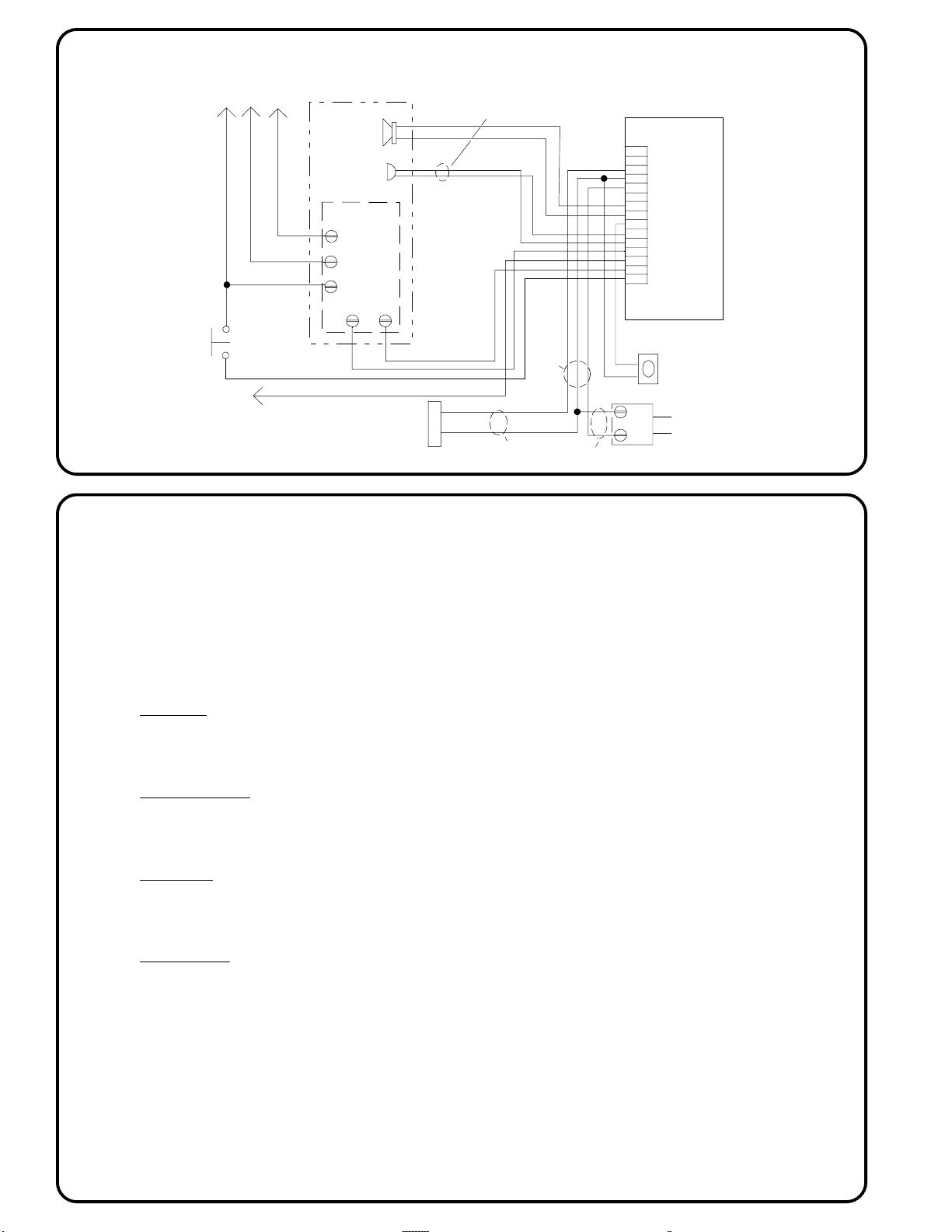
Fig. 2
Fi
.1
Door
Release SS102A
Transformer
2 cond. #18
Entrance
Panel
Add risers
as required.
suites
To additional
117 VAC