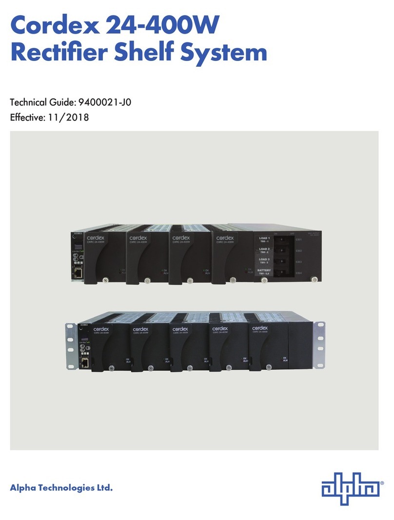
Alpha Technologies Cordex 12-250W User manual

Your Power Solutions Partner
Cordex 12-250W 19" Integrated Shelf
Up to 1250W with CXCI/CXCI+
Installation & Operation Manual
Part # 030-818-B2
Effective: 10/2013
member of The Group™


IMPORTANT SAFETY INSTRUCTIONS
SAVE THESE INSTRUCTIONS
1. Please read this manual prior to use to become familiar with the product’s numerous features and operating
procedures. To obtain a maximum degree of safety, follow the sequences as outlined.
2. This manual provides warnings and special notes for the user:
a. Points that are vital to the proper operation of the product or the safety of the operator are
indicated by the heading: WARNING.
b. A notation that is in Bold Italic typeface covers points that are important to the performance
or ease of use of the product.
3. Before using the product, read all instructions and cautionary markings on the product and any equipment
connected to the product.
4. Do not expose the product to rain or snow; install only in a clean, dry environment.
5. CAUTION – Unless otherwise noted, use of an attachment not recommended or sold by the product
manufacturer may result in a risk of fire, electric shock, or injury to persons.
6. CAUTION – Do not operate the product if it has received a sharp blow, it has been dropped, or otherwise
damaged in any way – return it to a qualified service center for repair.
7. CAUTION – Do not disassemble the product – call our qualified service centers for servicing. Incorrect
reassembling may result in a risk of electrical shock or fire.

i
TABLE OF CONTENTS
1INTRODUCTION ............................................................................................................................................................. 1
1.1 Scope of the Manual ..................................................................................................................................... 1
1.2 Product Overview.......................................................................................................................................... 1
1.3 Part Numbers and List Options..................................................................................................................... 2
2FEATURES ................................................................................................................................................................... 3
2.1 Cordex Integrated System Controller (CXCI/ CXCI+)................................................................................... 3
2.2 Rectifiers ....................................................................................................................................................... 6
2.3 Soft Start ....................................................................................................................................................... 7
3INSPECTION.................................................................................................................................................................. 9
3.1 Packing Materials.......................................................................................................................................... 9
3.2 Check for Damage ........................................................................................................................................ 9
4INSTALLATION ............................................................................................................................................................ 10
4.1 Safety Precautions ...................................................................................................................................... 10
4.2 Shelf Preparation/Mounting ........................................................................................................................ 10
4.3 Module Insertion/Removal .......................................................................................................................... 10
5WIRING AND CONNECTIONS ........................................................................................................................................ 11
5.1 Safety Precautions ...................................................................................................................................... 11
5.2 Tools Required............................................................................................................................................ 11
5.3 Power System Chassis Ground and DC Ground Reference ...................................................................... 11
5.4 AC Feeder Protection/Sizing....................................................................................................................... 11
5.5 AC Input Connections ................................................................................................................................. 12
5.6 Calculating Output Wire Size Requirements............................................................................................... 12
5.7 DC Output Connections .............................................................................................................................. 12
5.8 CAN Serial Ports ......................................................................................................................................... 12
5.9 Network Connection and Remote Communications via CXC..................................................................... 13
5.10 Signal Wiring Connections .......................................................................................................................... 13
6OPERATION................................................................................................................................................................ 16
6.1 Main Rectifier States ................................................................................................................................... 16
6.2 Main Rectifier Modes .................................................................................................................................. 17
6.3 Rectifier Factory Ranges and Defaults ....................................................................................................... 18
7SYSTEM STARTUP ...................................................................................................................................................... 19
7.1 Check System Connections ........................................................................................................................ 19
7.2 Verify AC and Power the Shelf ................................................................................................................... 19
7.3 Check Battery Polarity and Connect ........................................................................................................... 19
7.4 CXC Reset .................................................................................................................................................. 19
8MAINTENANCE ........................................................................................................................................................... 21
8.1 CXCI/CXCI+ Replacement Procedure........................................................................................................ 21
99.2 ACRONYMS AND DEFINITIONS ............................................................................................................................... 24
9.1 Acronyms and Definitions ........................................................................................................................... 24

030-818-B2 Rev B Page 1 of 24
1 Introduction
1.1 Scope of the Manual
This instruction manual explains the installation, interconnection, and operation of Alpha Technologies Cordex 12-
250W integrated 19" 2RU shelf with up to 1250W output power.
The following documents and drawings are included in this manual:
•Specifications, rectifier: 010-613-B1 (alt. 010-587-B1)
•Specifications, shelf: 030-818-B1
•Specifications, CXCI: 7400233-S0
•Schematic drawing: 030-783-05
•Outline drawing: 030-783-06
•Customer connections: 030-783-08
1.2 Product Overview
A complete Cordex rectifier system consists of a controller with one or more power modules in a common shelf
enclosure. The shelf has connections for AC inputs, DC output, and system communications.
Cordex rectifier modules use a high frequency, switched mode conversion technique to provide a fully regulated
and isolated DC output from the AC mains. The rectifier input is wide range to allow use on 120/208/220/240Vac
50/60Hz electrical service.
Rectifier power modules are “hot swappable” meaning they can be inserted or removed from the shelf without
cutting power to or from the system or the load.
Additional power modules can be included with the system at the time of ordering or added after the shelf has
been installed.
The rectifier shelf is designed to operate with the Alpha Cordex CXCI/CXCI+ (integrated version of the CXC
controller); which is built into the rectifier shelf.
Details for installation and wiring are provided in the respective chapters of this documentation package.
All models of the CXC allow the user to set up, control and monitor the entire power system and ancillary
components from one central, easy-to-use source: your web browser. The CXCI/CXCI+ models do not have a
touch screen display; system setup and management is performed exclusively with the web interface.
Details of controller operation are provided in the current version software manual.
Figure 1–Cordex 12-250W integrated 19" 2RU shelf
CXCI controller (integrated shelf)
Rectifier module

030-818-B2 Rev B Page 2 of 24
1.3 Part Numbers and List Options
This product is available to order under the following part numbers and list options:
Description Part Number/List Option
Cordex 12-250W 19" (flush mounting) 2RU shelf for systems up to 1250W (alt. #030-818-20) ...............030-783-20
[equipped to receive one CXCI/ CXCI+ controller and up to five CXRC 12-250W rectifiers] ....................... *List 0
120Vac input ........................................................................................................................................................List 5
240Vac input ........................................................................................................................................................List 6
19" rack, 6" offset mounting ...............................................................................................................................List 19
19" rack, flush mounting.....................................................................................................................................List 21
23" rack, 6" offset mounting ...............................................................................................................................List 23
23" rack, flush mounting.....................................................................................................................................List 25
Charcoal finish with white (contrasting) silkscreen .......................................................................................... *List 56
Temperature sensor, 1/4" lug, 12 ft....................................................................................................................List 72
Temperature sensor, 3/8" lug, 12 ft....................................................................................................................List 75
Bulk output ....................................................................................................................................................... *List 80
Two line cords without plugs, 3m each ..............................................................................................................List 89
Rectifier blank plate............................................................................................................................................List 90
Controller blank plate .........................................................................................................................................List 91
CXCI+ controller............................................................................................................................................... *List 98
CXCI controller ...................................................................................................................................................List 99
Cordex 12-250W rectifier power module (alt. #010-587-20)......................................................................010-613-20
Basic module, 12Vdc output .............................................................................................................................. *List 0
Charcoal finish with white (contrasting) silkscreen .......................................................................................... *List 56
Paralleling diode (Oring MOSFET) for operation without battery ......................................................................List 82
* Default option
The above information is valid at the time of publication. Consult factory for up-to-date ordering information.

030-818-B2 Rev B Page 3 of 24
2 Features
2.1 Cordex Integrated System Controller (CXCI/ CXCI+)
The CXCI/ CXCI+ controller is mounted in the rectifier system shelf and brings advanced monitoring technology to
the Cordex series of rectifiers. This compact system controller is designed for seamless operation and set up of
Alpha power systems and is equipped with the complete range of Cordex software features, including the
following:
•Designed to communicate directly with Cordex rectifiers
•Includes battery temperature compensation charging
•Battery performance diagnostics
•Provides local and remote communications
•User definable alarms
•Daily logging of power system events and system statistics
The CXCI/ CXCI+ includes a web server for easy set up and monitoring using an Internet connection with the
standard Windows Internet Explorer browser.
The data logging feature allows the user to capture data from multiple inputs, for AC/DC voltages, load/battery
current, cell voltages and temperatures (automatically for up to 16 user defined logs). Typical applications of the
CXCI logging include power system details, thermal performance of outdoor enclosures, battery cell specifics, or
mains variations captured by an AC voltage watchdog.
A built-in audio speaker sounds an intermittent tone during active alarms.
The input/output (I/O) board houses a series of terminal connections; located at the back of the system shelf.
NOTE: Customer settings for the CXCI/ CXCI+ is provided separately in the system documentation package.
2.1.1 System Controller Front Panel
2.1.1.1 Display
The CXCI (Figure 2) and CXCI+ (Figure 3) controllers have a 4-digit display for monitoring system voltage (V) and
current (A). A pushbutton switch toggles the display between the V and A readings.
Details of controller operation are provided in the current version software manual.
Figure 2–Cordex CXCI model system controller front panel
Hard reset
(push once)
Soft reset
(push once)
[Hold for 3 seconds
to reset IP address]
Ethernet port
LCD screen (V/A)
Display pushbutton
toggle switch (V/A)
Modem port
Illustration only and
may not exactly
match your
installation
System status
LEDs

030-818-B2 Rev B Page 4 of 24
Figure 3–Cordex CXCI+ model system controller front panel
2.1.1.2 LEDs
The controller has three LEDs located on the front panel. These are used to display the alarm status of the power
system, CXC progress and status during startup, file transfers and lamp tests.
Alarm Conditions
The controller illuminates the LED that corresponds to the system alarm status. The following show the
corresponding alarm status for each LED color:
Green – OK, no alarms present
Yellow – Minor alarm is present (no major alarms)
Red – Major alarm is present.
Only one LED is illuminated at a time during alarm conditions.
Progress and Status Indication
The LEDs are also used in the following situations:
Base unit validation – all three LEDs are on at the same time.
File transfer – when recovering from invalid firmware application – the red LED is illuminated.
Lamp Test – all three LEDs flash on and off at the same time for 2 seconds.
2.1.1.3 Reset
A reset button is located on the front panel for restarting the CXC’s microprocessor.
NOTE: Refer also to the software manual – always select the Reset menu item before pressing the reset button.
See Section 7.4 for more information on CXC Reset functions.
2.1.1.4 Modem Port (not available on the CXCI+, list 98)
The Modem port (front panel DB-9 connector, Figure 5) is designed for CXCI connection to the Alpha Cordex DC
Modem #018-585-20 (complete with Alpha cable).
2.1.1.5 Ethernet Port
The Ethernet port is designed for CXCI/ CXCI+ connection to a user supplied network (TCP/IP secured by user)
via a front panel RJ-45 jack (Figure 2) and a standard network cable.
Local access (e.g. laptop computer) is also possible from the Ethernet port connection using a standard network
crossover cable.
System status LEDs
Ethernet port
Display pushbutton toggle
Soft reset: push once
Reset IP address: hold for 3 seconds
LCD screen (V/A)
Hard reset
(push once)

030-818-B2 Rev B Page 5 of 24
2.1.2 Analog Input Channels
2.1.2.1 Voltage Inputs
Two voltage input channels, V1 and V2, provide monitoring of discharge and charge voltage. The CXC software is
pre-configured to monitor V1 for load voltage and V2 for battery voltage. V2 (wired internally) is used as the
system reference for rectifier float voltage, low voltage disconnect (LVD), system high voltage alarm, and system
low voltage alarm.
2.1.2.2 Current Input
The CXC software is pre-configured to monitor I1 for load current wired externally to the system current shunt.
2.1.2.3 Temperature Inputs
Two temperature input channels, T1 and T2, provide monitoring of battery temperature and temperature
compensation (temp comp) or room/ambient temperature. A voltage is supplied to these terminals to power the
temperature sensors.
2.1.3 Digital Input Channels
The CXCI/ CXCI+can accommodate up to two channels and can monitor digital alarm/control signals from
rectifiers, converters and many other types of equipment. See Section 5.10.2.
2.1.4 Alarm and Control Output Relays
The CXCI/ CXCI+contains four Form C digital alarm output relays to extend alarms and control external
apparatus. Each internally generated alarm or control signal may be mapped to any one of the relays, or, several
signals may be mapped to just one relay or none at all. See Section 5.10.3.
2.1.5 Network Connection and Remote Communications
The Cordex system can be set up, monitored and tested via ETHERNET 10/100 Base-T serial data connection.
The communication protocol supports a web interface.

030-818-B2 Rev B Page 6 of 24
2.2 Rectifiers
Figure 4–Cordex 12-250W rectifier front panel
2.2.1 Front Panel LEDs
The front panel LEDs provide rectifier status summary and help to locate a specific module under CXC control.
2.2.1.1 OK
The top LED (green) is on when AC is within valid range and the rectifier is delivering power to
the load.
The LED turns off when AC has failed or when the rectifier is off; e.g., when commanded via the
CXC. AC voltage is invalid if the AC Mains Low or AC Mains High alarm is active.
2.2.1.2 ALARM
The bottom LED (red) is on continuously in the event of an active Module Fail alarm.
The LED will flash (~2Hz) when a minor alarm is detected.
The LED remains off in the absence of an alarm.
2.2.1.3 LED Activity During ‘Locate Module’ Command from CXC
When the ‘locate module’ command has been received from the CXC, the LEDs will behave in a
distinctly different way so that the rectifier is easier to visually identify among adjacent rectifiers.
This state is entered when commanded via the CXC. The LEDs will flash in a distinct pattern
repeating every 2 seconds.
2.2.1.4 LED Activity During Firmware Upload
When a rectifier firmware upload is in progress, the LEDs will behave in the same way as the
‘locate module’ command described above.
2.2.2 Mechanical
A thumbscrew is provided to secure the rectifier into the shelf. During normal operation the rectifier shall be
locked into position. A handle (or grip) is incorporated into the front panel to facilitate the removal of the rectifier
from the shelf. No special tools are required.
2.2.3 True Module Fail Alarm
The power modules have a “true” fail alarm. This provides a true indication of the power module’s ability to source
current. When the module’s output current drops below 2.5% of the rated output a low output current condition is

030-818-B2 Rev B Page 7 of 24
detected and the Module Fail detection circuit is activated. This circuit momentarily ramps up the output voltage to
determine if the module will source current. If no increase in current is detected, the Module Fail alarm is
activated. The module will test once every 60 seconds for the condition until current is detected. Output voltage
ramping will cease upon detection of current1. A minimum 2.5% load is required to avoid the Ramp Test Fail
alarm; this can typically be provided with the parallel system battery. Activation of this alarm could indicate a failed
module or a failed load.
NOTE: For Cordex rectifier systems without batteries (or with a very light load; below 2.5% of rated output) it is
recommended that the ramp test be disabled to avoid nuisance alarms. The Ramp Test feature is
enabled/disabled via the CXC menu item: Rectifiers, Configure Settings.
2.2.4 Heat Dissipation
Heat dissipation is achieved through natural (bottom to top) convection cooling.
2.2.5 Over Temperature Protection
Each rectifier module is protected in the event of an excessive increase in temperature due to component failure
or cooling airflow blockage. During over temperature conditions, the rectifier limits the output power as well as the
output current. If temperature continues to increase, a shutdown of the rectifier is initiated. The rectifier shall
restart automatically if the temperature has returned to a safe level.
2.2.6 Wide AC Range
A minor alarm is generated when the AC input voltage drops below specification. The unit will deliver derated
output power down to 80Vac.
For voltages above 277Vac, power factor and total harmonic distortion may be derated. Up to 320Vac, the
rectifier will be operational and shall not suffer any damage.
2.2.7 AC Inrush/Transient Suppression
The inrush current of the rectifier module is limited to the full load steady state line current to prevent surge on the
AC line. Modules are also protected from input lightning and transient surges in accordance with IEEE/ANSI
C62.41 Category B3.
2.3 Soft Start
To eliminate an instantaneous demand on the AC source, a soft start feature is employed. Soft Start, sometimes
referred to as “current walk-in”, works by gradually (up to five seconds) ramping the current limit up from zero to
the actual or defined customer setting. The rectifier output voltage is ramped up from the minimum voltage to the
float voltage.
2.3.1 Start Delay
The rectifier modules are equipped with a delay timer in order to stagger start a series of modules to prevent
excessive loading of generators upon start up. The built-in timer delays the turn on of the module depending on
the value selected (up to 120 seconds) via the CXC. A minimum one-second delay is preset to allow charging of
the input capacitors.
2.3.2 Current Limit/Short Circuit Protection
The current limit function determines the maximum output current limit of the rectifier module, regardless of output
voltage or power. Maximum output current is limited to a constant value down to short circuit condition. Current
limiting can be used to mate the rectifier output current ampacity to the needs of the load and parallel battery to
minimize excessive battery recharge current.
The rectifier will sustain a short circuit at the output terminals indefinitely. The maximum short circuit current shall
not exceed 105% of the rated full load current.
1Under normal conditions, a battery connected to the output of the rectifier will draw current when the voltage ramp occurs. Therefore the rectifier fail
alarm will not be generated with a battery connected.

030-818-B2 Rev B Page 8 of 24
2.3.3 Power Limiting
Each rectifier module is designed to limit power output to the module specification. This enables more current to
be supplied at lower output voltages, and allows matching of output to the demand of constant power loads,
normally seen with telecom equipment.
This feature may also be used for a faster recharge of flooded batteries paralleled with the load.
NOTE: Current limiting overrides the power-limiting feature.
2.3.4 High Voltage Shutdown (HVSD)
This feature provides protection to the load from over voltage conditions originating from the rectifiers. It operates
by shutting down the offending rectifier module when a high output voltage condition occurs. Indication is through
the red Alarm (Module Fail) LED. Modules will restart automatically; however, if more than three over voltage
conditions occur in one minute, the module will latch off and remain shut down until it is reset.
2.3.5 Battery Eliminator Operation
Rectifier modules maintain all specifications (except where indicated) with or without a battery attached in parallel
to the output; however, if a battery or another module supplying DC voltage in parallel is not present, there will be
no monitoring or control activity if there is an AC power failure or input fuse failure.
2.3.6 Paralleling Diode (optional)
An optional Oring MOSFET on the output prevents disruption of DC system output power in the event of a rectifier
internal fault in systems without batteries.
NOTE: Maximum output power of a 250W rectifier is reduced to 246W with this option.

030-818-B2 Rev B Page 9 of 24
3 Inspection
3.1 Packing Materials
All Alpha products are shipped in rugged cardboard boxes and suspended via solid inserts to minimize shock that
may occur during transportation. Packaging assemblies and methods are tested to International Safe Transit
Association standards.
3.1.1 Returns for Service
Save the original shipping container. If the product needs to be returned for service, it should be packaged in its
original shipping container. If the original container is unavailable, make sure the product is packed with at least
three inches of shock-absorbing material to prevent shipping damage.
NOTE: Alpha Technologies is not responsible for damage caused by the improper packaging of returned products.
3.2 Check for Damage
Prior to unpacking the product, note any damage to the shipping container. Unpack the product and inspect the
exterior for damage. If any damage is observed contact the carrier immediately.
Continue the inspection for any internal damage. In the unlikely event of internal damage, please inform the
carrier and contact Alpha Technologies for advice on the impact of any damage.
Verify that you have all the necessary parts per your order for proper assembly.

030-818-B2 Rev B Page 10 of 24
4 Installation
This chapter is provided for qualified personnel to install the shelf in a clean and dry environment.
NOTE: To aid the user with installation, frequent reference is made to drawings located at the rear of the manual.
4.1 Safety Precautions
WARNING
Hazardous voltages are present at the input of power systems. The DC output from the rectifiers
and battery system, though not dangerous in voltage, has a high short circuit current capacity
that may cause severe burns and electrical arcing.
Before working with any live battery or power system/distribution center, follow these precautions:
•Remove all metallic jewelry; e.g., watches, rings, metal rimmed glasses, necklaces.
•Wear safety glasses with side shields (and prescription lenses if necessary) at all times during installation.
Metallic tools must be insulated.
The installer should follow all applicable local rules and regulations for electrical and battery installations; e.g.,
CSA, UL, CEC, NEC, OSHA, and local fire codes.
4.2 Shelf Preparation/Mounting
The shelf has been designed for flush or 6” offset mounting in a 19” or 23” rack. See drawing 030-783-06.
NOTE: The shelf shall be mounted in a clean and dry environment. Allow at least 1.75” of free space above and below
the unit for unrestricted cooling airflow. 3.5” (2RU) is recommended.
Mounting brackets accommodate either 1" or 1-3/4" rack spacing. The shelf should be mounted to the rack using
at least two #12 – 24 x 1/2" screws in each bracket. Philips-type screws and screwdriver should be used to
eliminate the possibility of slippage and scratching of the unit’s exterior. Washers (such as internal tooth) or
special screws that are designed to cut through the painted surface should be used to ensure a good chassis
ground.
4.3 Module Insertion/Removal
Insert by placing the module on the shelf bottom and sliding the module into the rear connector (inside of the
shelf). Apply pressure on the module handle to engage the rear connector in the shelf receptacle.
NOTE: It is recommended that the first module be inserted into the front leftmost position using the side of the shelf-
mounted controller as a guide. The next module may be inserted using the previous module as a guide.
Tighten the screw on the bottom of the faceplate to secure the module to the shelf.
NOTE: Do not force a module into position if it does not seat properly. All modules are keyed to ensure that the correct
module (polarity/voltage) type is used.
To remove a module, loosen the screw on the bottom of the faceplate. Grasp handle and pull out, sliding the
module away from the rear connector and out of the shelf.

030-818-B2 Rev B Page 11 of 24
5 Wiring and Connections
This chapter provides cabling details and notes on cable sizing for DC applications with respect to the shelf.
NOTE: Refer also to foldout drawings located at the rear of the manual.
5.1 Safety Precautions
WARNING
Hazardous AC voltages may be present. Ensure power at the AC service panel is off before
attempting work on the AC connections. Use a voltmeter to verify the absence of voltage. Clearly
mark the correct polarity of the battery leads before commencing work on DC connections.
Refer to the previous (Installation) chapter for additional safety precautions.
5.2 Tools Required
Various tools are essential for product installation. Use this list as a guide:
•Slot head screwdrivers (blade sizes: 1/4", 1/8", 1/16")
•Philips head screwdriver, #2 (tip size 3/16")
•Digital voltmeter equipped with test leads
•Adjustable 12Vdc load (optional)
•Cutters and wire strippers
•Crimping tool (optional for large gauge wire)
•Socket and rachet set (Imperial measure)
•Anti-static wrist strap
•Computer (laptop) with MicrosoftInternet Explorer 6 or greater
•Crossover cable RJ-45 (for access using the Ethernet port).
5.3 Power System Chassis Ground and DC Ground Reference
WARNING
For safety reasons, ensure the system is properly bonded to the building’s ground grid.
Both the shelf chassis ground (via power system chassis ground) and common return shall be connected to the
site ground to ensure correct operation of the system and to prevent drifting floating analog (especially current)
readings.
5.4 AC Feeder Protection/Sizing
To maximize system reliability, a dual AC feed divides the rectifiers into two groups to be supplied by two
separate feeds. See customer connections drawing (modules are numbered left to right). TB3 feeds modules 1
and 2. TB4 feeds modules 3, 4 and 5.
It is recommended for each feed to use a dedicated protection feeder breaker located at the AC distribution panel.
The feeder breaker can also act as the disconnect device for the connected modules.
Number of Rectifiers
on AC Feed
Circuit Breaker
Exact Value to Use (A)
90 deg. C Wire Gauge
to use at 30 deg. C
ambient (AWG)
1
10
14
2
10
14
3
15
14
Table A–Recommended AC supply configuration

030-818-B2 Rev B Page 12 of 24
5.5 AC Input Connections
CAUTION: AC input wires should be routed in flexible or rigid conduit as far away as possible
from the DC power wires to minimize EMI disturbances.
If the shelf is factory-equipped with a line cord, proceed to the next section.
Refer to customer connections drawing 030-783-08 (rear view – back cover removed).
Remove the metal cover from the rear of the shelf to expose the wireway for the input terminal blocks.
Attach the conduit retainers to the wireway hole(s) and route the AC cables through. Secure the wires to the AC
input and chassis ground terminals as required. Tighten the cable connector to the AC cable (conduit similar).
Replace rear cover once all connections have been completed.
5.6 Calculating Output Wire Size Requirements
Wire size is calculated by first determining the appropriate maximum voltage drop requirement. Using the formula
below calculate the CMA wire size requirement. Determine the size and number of conductors required to satisfy
the CMA requirement.
CMA = (A x LF x K) / AVD, where:
CMA = Cross section of wire in circular MIL area
A = Ultimate drain in amps
LF = Conductor loop feet
K = 11.1 constant factor for commercial (TW type) copper wire
AVD = Allowable voltage drop
Check again that the ampacity rating of the cable meets the requirement for the installation application. Consult
local electrical codes (NEC, CEC, etc.) for guidelines. If required, increase the size of the cable to meet the code.
5.7 DC Output Connections
WARNING
Leave cables disconnected at battery and verify output polarity using a voltmeter. Make battery
connections only after all other wiring is completed.
DC output wire shall be UL approved XHHW or RHH/RHW (for Canadian users, RW90 Type). Control and sense
wires shall be UL approved Style 1015 (for Canadian users, TEW type).
Secure the positive and negative cable leads to the shelf output terminal blocks of the correct polarity; i.e.,
+Vcable to +Vpost.
Connect the common output leg of the rectifier system to ground. This connection is typically made at the load
common termination point (negative bus bar for +12V systems).
Replace rear cover once all connections have been completed.
5.8 CAN Serial Ports
A CAN Out port (modular jack with offset latch), is provided for communications with Alpha Cordex rectifiers and
other CAN-enabled equipment. A CAN In port is also provided for an external controller if this shelf does not have
a CXCI (List 99) or a CXCI+ (List 98). These ports are located on the shelf backplane.
Daisy-chain from shelf to shelf (CAN OUT of one shelf to CAN IN of another) as necessary and ensure that only
the last shelf is terminated. See drawing 030-783-08.
5.8.1 CAN Termination
A jumper (or switch depending on your configuration) allows setting of the CAN OUT to be open (to the next shelf
in the system) or terminated. Termination must be enabled in final shelf on the CAN bus only.

030-818-B2 Rev B Page 13 of 24
5.9 Network Connection and Remote Communications via CXC
The Cordex system can be set up, monitored and tested via modem or ETHERNET 10/100 Base-T serial data
connection. The communication protocol supports a web interface. Some standard scenarios are described
below:
5.9.1 Modem Port (CXCI Controller Only)
The Modem port is designed for CXCI connection to a user supplied modem via a front panel DB-9 connector.
Connect to the CXCI from the modem with a straight through cable.
5.9.2 Ethernet Port for Network Connection (Standard Network Cable)
The Ethernet port is designed for CXCI/ CXCI+ connection to a user supplied network (TCP/IP secured by user)
via a front panel RJ-45 jack.
Connect to the CXCI/ CXCI+using a standard network cable. Pinouts are shown in drawing 030-783-08.
5.9.3 Ethernet Port for Local Connection (Crossover Cable)
Local access (e.g. laptop computer) is also possible from the Ethernet port connection using a standard network
crossover cable.
5.10 Signal Wiring Connections
For terminal block connections, the recommended wire sizes are 0.129 to 0.823mm2(#26 to #18AWG) for the
temperature range of 0 to 50 deg. C (as per UL/CSA).
CAUTION: to reduce risk of fire, use only 0.129mm2(#26 AWG) or larger wire.
Terminal
Description
Default Name
Signal Type
Range
1, 2, 3*
LVD Control (internal)
K1, Relay 1
NO/COM/NC
60VDC / 1A
4, 5, 6*
Alarm Output 2
K2, Relay 2
NO/COM/NC
60VDC / 1A
7, 8, 9*
Alarm Output 3
K3, Relay 3
NO/COM/NC
60VDC / 1A
10, 11, 12*
Alarm Output 4
K4, Relay 4
NO/COM/NC
60VDC / 1A
13, 14**
Digital Input 1 (internal)
D1, Digital 1
Pos (+) or Neg (-)
0—60VDC
15, 16**
Digital Input 2
D2, Digital 2
Pos (+) or Neg (-)
0—60VDC
17, 18***
Voltage Input 1
V1, Load Voltage
Pos (+) / Neg (-)
0—60VDC
19, 20***
Temp Probe 1
T1, Analog Input T1
Pos (+) / Neg (-)
0—20VDC
21, 22***
Temp Probe 2
T2, Analog Input T2
Pos (+) / Neg (-)
0—20VDC
23
Battery +12V
Batt Hot
Neg (-)
20—60VDC
24, 25
Current Input 1 (internal)
I1, Load Current
Pos (+) / Neg (-)
±50mV
Table B–Wiring connections for CXCI
* NO and NC Form C contacts available. Can be configured to de-energize on alarm (DOA) or energize on alarm (EOA).
** See Table C for definitions of logic and system.
*** Voltage (Input) is 0—60VDC, Temp Probe is 0—20VDC with power source.
NOTE: To aid the user with installation, frequent reference is made to drawings located at the rear of this manual.
Custom configurations may be detailed within the Alpha power system documentation package.
The input cables should be bundled together and routed through the entry holes of the shelf, if applicable.

030-818-B2 Rev B Page 14 of 24
5.10.1 Analog Inputs for CXCI/ CXCI+
CAUTION: Ensure the correct polarity is used for all input cable terminations.
The analog input channels are used to monitor various types of electrical signals.
5.10.1.1 Voltage
Voltage Input #1 (load voltage per CXC software) terminals on the shelf (V1 on TB12) provide
connections to an optional secondary voltage input. For example, this can be terminated to the
load side of an LVD contactor to monitor load voltage.
Voltage Input #2 (battery voltage per CXC software) is wired internally to the rectifier output
voltage of the shelf. This is used as the reference for system alarming (such as high voltage)
and control (such as LVD).
The Battery +12V should be connected at the battery system voltage terminal for CXCI/ CXCI+
reference when a battery disconnect device is used. It is critical to CXC operation as it ensures
a source of power to the CXC should the disconnect device open the circuit.
5.10.1.2 Temperature Sensor
Temperature Probe input channels (T1 and T2 on TB12) provide connections for up to two
temperature sensors. A voltage is supplied to these terminals for sensor measurements.
5.10.1.3 Current
Current Input #1 (load current per CXC software) is used for an external 50mV current shunt.
5.10.2 Digital Inputs for CXCI/ CXCI+
The digital input channels (factory-installed) are used to monitor various alarm and control signals. All input
channels are voltage activated and accept a bipolar (i.e. negative or positive) DC signal directly.
D1 and D2 on TB12 are available for customer connections as required.
5.10.2.1 Connection Method
Typical Alpha systems use the “reset with Hot and trigger with Ground” connection. The digital
input is wired in such a way that the Hot is wired directly into one of the input terminals; e.g.,
positive input for +12V systems. The other input terminal is wired to the Ground (common) of
the system through a relay (dry contact – usually located on the equipment requiring
monitoring). This method (see Figure 5) allows the digital input to receive (or not receive) a
Ground signal on an alarm.
Figure 5–Showing digital input connection method

030-818-B2 Rev B Page 15 of 24
5.10.2.2 Programming the Digital Input
The digital input channels can be programmed for “active high” or “active low.” Active high
indicates “alarm on the presence of a ground signal” and active low indicates “alarm on the
removal of a ground signal.” See CXC Software manual for detailed instruction on
programming.
Voltage Range (VDC)
Voltage Level (VDC)
Considered As “0” (Off)
Voltage Level (VDC)
Considered As “1” (On)
0—60
(system voltage setting)
0—3 9—60
Table C–Voltage level definitions for digital inputs
5.10.3 Alarm (Relay) Outputs
Terminals provide contacts for extending various alarm or control signals. Each relay output can be wired for NO
or NC operation during an alarm or control condition. See Figure 6.
Figure 6–Showing relay connections
Relays can be programmed to energize or de-energize during an alarm condition (see CXC Software manual).
When the CXCI/ CXCI+ reset button is pressed or power is lost, all relays de-energize.
These relays could be used for additional external LVD contactor control.
5.10.4 LVD Control Alternative
The LVD Control functions can be hardwired directly from an alarm output relay to an external LVD contactor (or
panel). See Controls menu defaults (Controls > Configure Controls) in the CXC Software manual.
5.10.5 LVD Inhibit
Should it be necessary to remove the CXCI/ CXCI+, the customer connection board (on the back of the shelf)
provides shorting pins (JP2) to inhibit (or override) the LVD Control function. Refer to CXCI/ CXCI+ replacement
procedure in Section 8.1 on page 21.

030-818-B2 Rev B Page 16 of 24
6 Operation
6.1 Main Rectifier States
Rectifier operation can be broken up into five main states:
1. Off,
2. Start delay,
3. Soft start,
4. Normal operation,
5. Turning off.
Each state is characterized as being distinct and necessary for the operation of the rectifier. These states are
briefly described below.
6.1.1 Off State
The rectifier will be in the Off state immediately after power is applied to the rectifier or after a rectifier shutdown.
The shutdown source may be remote or local shutdown, AC shutdown, OVP or thermal shutdown.
When the rectifier is in this state the DC-DC converter is turned off and the CXC will be monitoring its inputs for
the proper conditions to begin the start up sequence.
When the conditions have been met for the rectifier to start up, it will transition to the Start Delay state.
6.1.2 Start Delay State
When the rectifier is in the Start Delay state, the DC-DC converter is held off and still not sourcing power and is
waiting for a given amount of time before transitioning to the next state.
When in this state, the CXC continues to monitor its inputs.
After the Start Delay state the rectifier will transition to the Soft Start state.
NOTE: Soft start, or current walk-in, gradually increases the voltage and current output of the rectifier upon startup. This
is done to reduce the instantaneous load on the AC source.
6.1.3 Soft Start State
When the Soft Start state is entered, the rectifier will be turned on and the output voltage and output current will
be gradually increased. If a load is present, the rectifier will begin to source power.
When the voltage and current limit ramps have finished, the rectifier will transition to the Normal Operation state.
6.1.4 Normal Operation State
The Normal Operation state is the state that the rectifier will be in performing all of the rectifier functions and
features specified herein.
From this state, the only valid transition is to the Turning Off state. This transition will happen if the rectifier is
required to shut down.
6.1.5 Turning Off State
The Turning Off state is entered because a short delay is required before the rectifier actually turns off to take
care of any initialization requirements.
When this short delay has elapsed, a transition to the Off state is made.
Table of contents
Other Alpha Technologies Indoor Furnishing manuals
Popular Indoor Furnishing manuals by other brands

LDI Spaces
LDI Spaces Safco Rumba 2005 Assembly instructions

NOVO
NOVO Carmen A Frame Sofa Bed Assembly instructions

Meble Wojcik
Meble Wojcik HOBBY PRO-018-3101 Assembly instructions

Golden Technologies
Golden Technologies DeLuna Titan owner's manual

Wampat
Wampat W04H4121G Assembly instructions

Woltra
Woltra MURANI MU-22 Assembly instructions