Alpha 9500 HF User manual

Alpha Radio Products
Product Release 1
DOCNUMBER 9500
Document Issue 1, Revision 7
June 2009 i
Alpha 9500 HF Linear Amplifier
Operating Manual
Alpha Radio Products
www.alpharadioproducts.com
Product Release 1
Document Issue 1, Revision 7
June 2009

Alpha 9500 HF Linear Amplifier Operating Manual Alpha Radio Products
Product Release 1
DOCNUMBER 9500
Document Issue 1, Revision 7
ii June 2009
Alpha 9500 HF Linear Amplifier Operating
Manual
Prepared for Alpha Radio Products by: MRH/LJW
To obtain copies of this document, go to www.alpharadioproducts.com
Copyright © 2007–2009 Alpha Radio Products, Inc. All rights reserved.
Specifications subject to change without notice.

Alpha Radio Products
Product Release 1 Contents
DOCNUMBER 9500
Document Issue 1, Revision 7
June 2009 iii
Contents
1. Introduction . . . . . . . . . . . . . . . . . . . . . . . . . . . . . . . . . . . . 1-1
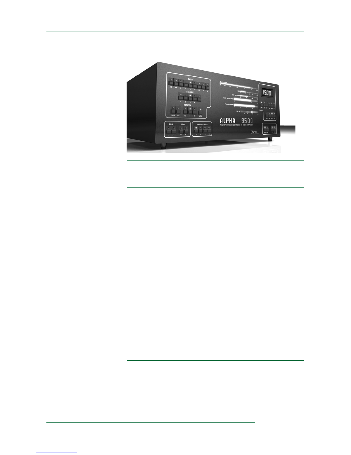
1.1 Product Description 1-1
1.2 Product Capabilities 1-2
1.3 Safety Considerations 1-2
1.4 Related Products 1-3
1.5 Assistance 1-4
2. Amplifier Components . . . . . . . . . . . . . . . . . . . . . . . . . . . . . . 2-1
2.1 Cathode (Input-Match) Board 2-2
2.2 Center-Partition Board 2-3
2.3 Connections 2-3
2.4 Controls and Display 2-3
2.5 Display Board 2-5
2.6 Firmware 2-5
2.7 Master-Control Board 2-6
2.8 Output-Tank Circuit 2-6
2.9 Power Supply 2-7
2.10 Tube and Tube Deck 2-8
3. Installation Overview . . . . . . . . . . . . . . . . . . . . . . . . . . . . . . . 3-1
3.1 Prepare Your Station 3-1
3.2 Unpack the Amplifier and Transformer 3-2
3.3 Install the Transformer 3-2
3.4 Connect the Transformer 3-2
3.5 Connect the Cables 3-3
3.6 Set the Input Drive 3-3
3.7 Connect the Transceiver 3-3
4. Preparing Your Station . . . . . . . . . . . . . . . . . . . . . . . . . . . . . . 4-1
4.1 Prepare Your Station 4-1
4.2 Limitations of Operation at 90–130 VAC 4-4
5. Setting Up the Amplifier . . . . . . . . . . . . . . . . . . . . . . . . . . . . . 5-1
5.1 Unpack the Amplifier and Transformer 5-1
5.2 Install the Transformer 5-3
5.3 Connect the Transformer 5-4
5.4 Connect the Cables 5-7
5.5 Set the Input Drive 5-10
5.6 Connect the Transceiver 5-10
6. Operating the Amplifier . . . . . . . . . . . . . . . . . . . . . . . . . . . . . . 6-1
6.1 Operate the Amplifier 6-1
6.2 (Optional) Set Up to Operate from a PC 6-3
6.3 Put the Amplifier into the Desired State 6-3

Alpha 9500 HF Linear Amplifier Operating Manual Alpha Radio Products
Contents Product Release 1
DOCNUMBER 9500
Document Issue 1, Revision 7
iv June 2009
6.4 Tune the Amplifier 6-5
6.5 Program the Amplifier Memory 6-9
7. Operating the Amplifier from a PC Interface . . . . . . . . . . . . . . . . . . 7-1
7.1 Set Up to Operate from a PC 7-2
7.2 Operate from the PC 7-2
8. Maintaining and Upgrading the Amplifier . . . . . . . . . . . . . . . . . . . . 8-1
8.1 Clean the Chassis 8-1
8.2 Retune the Amplifier 8-2
8.3 Replace the Tube and Fuses 8-3
8.4 Upgrade Firmware 8-4
9. Diagnosing Faults . . . . . . . . . . . . . . . . . . . . . . . . . . . . . . . . . 9-1
9.1 Overview 9-1
9.2 Fault Codes and Resolutions 9-1
Terminology 1-1

Alpha Radio Products
Product Release 1 List of Procedures
DOCNUMBER 9500
Document Issue 1, Revision 7
June 2009 v
List of Procedures
Procedure 4-1, “Prepare your station,” page 4–1
Procedure 5-1, “Unpack the amplifier and transformer,” page 5–1
Procedure 5-2, “Install the transformer,” page 5–3
Procedure 5-3, “Connect the transformer,” page 5–4
Procedure 5-4, “Connect the cables,” page 5–7
Procedure 5-5, “Set the input drive,” page 5–10
Procedure 5-6, “Connect the transceiver,” page 5–10
Procedure 6-1, “Operate the amplifier,” page 6–1
Procedure 6-2, “Tuning the amplifier,” page 6–6
Procedure 6-3, “Program the memory,” page 6–10
Procedure 7-1, “Set up to operate from a PC,” page 7–2
Procedure 8-1, “Clean the amplifier,” page 8–1
Procedure 8-2, “Retune the amplifier,” page 8–2
Procedure 8-3, “Replace the tube and fuses,” page 8–4
Procedure 8-4, “Upgrade firmware on the primary board,” page 8–5
Procedure 8-5, “Upgrade firmware on the secondary boards,” page 8–8

Alpha 9500 HF Linear Amplifier Operating Manual Alpha Radio Products
List of Procedures Product Release 1
DOCNUMBER 9500
Document Issue 1, Revision 7
vi June 2009

Alpha Radio Products
Product Release 1 1
DOCNUMBER 9500
Document Issue 1, Revision 7
June 2009 Page 1–1
1 Introduction
1.1 Product Description 1–1
1.2 Product Capabilities 1–2
1.3 Safety Considerations 1–2
1.4 Related Products 1–3
1.5 Assistance 1–4
Congratulations on your purchase of a professional-quality Alpha 9500
HF linear amplifier.
1.1 Product Description
The ALPHA 9500 (see Figure 1-1) is a self-contained auto-tune HF linear
power amplifier. It is capable of continuous operation at 1500 W peak
power output on single sideband (SSB), keyed continuous wave (CW),
slow-scan television (SSTV), radioteletype (RTTY), digital modes or
FM, with no time limit.
With proper installation and care, you can expect to enjoy your amateur
radio hobby with this amplifier for many years to come.
CAUTION
!
CAUTION! Study this manual carefully before operating your
amplifier for the first time. In particular, it is extremely important that
you thoroughly review the installation and operation sections. Failure
to do so could result in serious damage not covered under warranty.

Alpha 9500 HF Linear Amplifier Operating Manual Alpha Radio Products
Introduction Product Release 1
DOCNUMBER 9500
Document Issue 1, Revision 7
Page 1–2 June 2009
11
1
Figure 1-1 ALPHA 9500
1.2 Product Capabilities
Product capabilities include:
•Continuous RF output. The ALPHA 9500 is capable of 1.5 kW
continuous RF output on all commonly used modes and on any
authorized amateur frequency from 1.8 to 29.7 MHz (other than the
60-MHz band).
•Compatibility with popular amateur transceivers and exciters. The
ALPHA 9500 requires approximately 50-65 W peak RF drive for
1.5-kW output.
•Capable of full CW break-in, QSK, and all digital modes when used
with any appropriate transceiver.
•Built-in protective functions. The control system incorporates
protective functions that minimize the probability of accidental
damage to the amplifier or its power tubes. In most cases, when one
of the protective functions is tripped, the amplifier goes to standby.
•USB and serial interface allow for remote operations, diagnostics,
and firmware upgrades.
1.3 Safety Considerations
•Locate the ALPHA 9500 where there is good air circulation all
around and on top of the cabinet. The unit may become hot during
operation.

1
DOCNUMBER 9500
Document Issue 1, Revision 7
June 2009 Page 1–3
Alpha Radio Products Alpha 9500 HF Linear Amplifier Operating Manual
Product Release 1 Introduction
•Use proper lifting techniques and two people when moving the
ALPHA 9500. The ALPHA 9500 weighs approximately 69 pounds
when the transformer is installed.
•Although the ALPHA 9500 meets international safety standards and
FCC regulations, remember that the equipment works with high
voltages that can be LETHAL!
This operating manual holds information, cautions, and warnings that you
must follow to ensure safe installation and operation. Read Chapter 1
before attempting to unpack or operate the ALPHA 9500. Failure to
perform procedures properly may result in amplifier damage, fire hazard,
or electric shock.
It is particularly important that you:
•Never open the amplifier case without unplugging the unit from the
wall outlet.
•Never stick objects into holes in the case.
•Never touch an antenna during transmission.
•Never attempt to turn on the amplifier without the cover securely in
place (all attachment screws reinserted).
•Never turn the amplifier back on after a hard fault without waiting at
least 20 seconds.
•Never press the ON (AMP) button after the amplifier faults to power
off.
•Never allow liquids to enter the amplifier through the cover holes.
•Never cover or obscure the exhaust holes in the cover of the amp.
1.4 Related Products
Other Alpha products available to enhance your use of the ALPHA 9500
include:
•ALPHA 2100 full-1500 W-rated 50-ohm dummy loads
•ALPHA 4500 series SWR meters and wattmeters
For more information, go to www.alpharadioproducts.com or call 303-
473-9232.

Alpha 9500 HF Linear Amplifier Operating Manual Alpha Radio Products
Introduction Product Release 1
DOCNUMBER 9500
Document Issue 1, Revision 7
Page 1–4 June 2009
11
1
1.5 Assistance
Technical assistancefrom Alpha Radio Products is available from several
sources.
•Go to our website at www.alpharadioproducts.com and click
Support. On this site you can get the following assistance:
•FAQs
•Legacy equipment information
•Manuals
•Repair information
•Software downloads
•Tech tips
•Technical support
•E-mail us at service@alpharadioproducts.com.
•Fax us at 303-473-9660.
•Phone us at 303-473-9232.

Alpha Radio Products
Product Release 1 2
DOCNUMBER 9500
Document Issue 1, Revision 7
June 2009 Page 2–1
2 Amplifier Components
2.1 Cathode (Input-Match) Board 2–2
2.2 Center-Partition Board 2–3
2.3 Connections 2–3
2.4 Controls and Display 2–3
2.5 Display Board 2–5
2.6 Firmware 2–5
2.7 Master-Control Board 2–6
2.8 Output-Tank Circuit 2–6
2.9 Power Supply 2–7
2.10 Tube and Tube Deck 2–8
The ALPHA 9500 uses a single 3CX1500 (8877) high-mu external-anode
triode ceramic tube for amplification. The main power supply is an
unregulated transformer/rectifier/capacitor power supply for the high-
voltage (HV) and heater circuits. All other power supplies are regulated.
The biasing and tank circuits are similar in most respects to those of the
ALPHA 9500’s predecessor, the ALPHA 77. The unit has thoroughly
modern computer-controlled power supply and control circuitry.
Extensive safety measures protect the amplifier against most off-nominal
conditions. It has USB and RS-232 interfaces to aid in remote operation.
All front-panel features are accessible via these interfaces.
There are six main circuit boards in the amplifier. Communications
among these is via an I2C bus.
The amplifier front and back are shown below (see Figure 2-1 and
Figure 2-2).Amplifiercomponentsarelistedalphabeticallyanddescribed
below.

Alpha 9500 HF Linear Amplifier Operating Manual Alpha Radio Products
Amplifier Components Product Release 1
DOCNUMBER 9500
Document Issue 1, Revision 7
Page 2–2 June 2009
22
2
Figure 2-1 Amplifier front and interior
Figure 2-2 Amplifier back
2.1 Cathode (Input-Match) Board
The cathode board, housed in the tube deck, consists of a set of Pi filters
controlled bya set offive relays thatare enabledbased on theband-switch
setting.

2
DOCNUMBER 9500
Document Issue 1, Revision 7
June 2009 Page 2–3
Alpha Radio Products Alpha 9500 HF Linear Amplifier Operating Manual
Product Release 1 Amplifier Components
2.2 Center-Partition Board
The center-partition board contains the RF decoupling circuit on the B+
line as well as the crowbar safety circuit. When you remove the top cover
of the ALPHA 9500, the spring metal of this safety device shorts out the
B+ line.
2.3 Connections
When the ALPHA 9500 is powered up, it measures the line voltage and
chooses, then sets the appropriate tap setting for the transformer primary.
After it is powered up, it does not reset the tap. The amplifier can be set
to override autotaps election and use any primary tap; it may be useful to
do so if your line voltage is unsteady or on the edge of a tap setting. For
more information, contact ALPHA technical support.
Figure 2-3 Primary connections
2.4 Controls and Display
The ALPHA 9500 controls enable you to adjust and monitor the amplifier
as needed (see Figure 2-4).

Alpha 9500 HF Linear Amplifier Operating Manual Alpha Radio Products
Amplifier Components Product Release 1
DOCNUMBER 9500
Document Issue 1, Revision 7
Page 2–4 June 2009
22
2
!
IMPORTANT Note that the front panel has, in the upper-right corner, a 7-segment
LED display (so named because one can, by individually turning on
or off each of just 7 simple bars, display any single digit 0 to 9). The
display contains 4 such digits.
The buttons below the display control what kind of value is displayed:
FLT, Fwd, Ig, Ip, SWR, or Vp.
Figure 2-4 Amplifier controls
BAND
MEMORY
SAVE RCL DEF 1 2 AUTO
TUNE LOAD ANTENNA SELECT
1.8 3.5 7 10 14 18 21 24 28
12345
1234
RF Power kW
SWR
Grid Current mA
Plate Current Amps
Plate Voltage kV
Gain
0 0.1 0.3 0.6 1.0 1.5 2.5
1 1.5 2 3 >10
0 50 100 150
0 1.0 1.5
02314
10 30 50
MICROPROCESSOR CONTROLLED HFLINEAR AMPLIFIER
ALPHA
Fwd IpVpIg SWR FLT
DIM SND PEP DEL
OPER STBY ON/OFFON
ANT SELAMP
SEGMENT
9500
Table 2-1 Amplifier Buttons (listed alphabetically)
Button Purpose
ANTENNA SELECT Determines which one or two of the four antenna output ports to use.
BAND Selects an amateur band, designated in megahertz (MHz).
DEL Displays the delivered power from theamplifier to the selected antenna
port in watts (W).
DIM Controls the brightness of the display LEDs.
FLT Sets the 7-segment display to show the last fault. Also loads new
firmware.
Fwd Sets the 7-segment display to show forward power in W.
GAIN Displays the gain in decibels (dB).
GRID CURRENT Displays the grid current in milliamperes (mA).
Ig Sets the 7-segment display to show grid current in mA.
Ip Sets the 7-segment display to show plate current in mA.
LOAD Controls the load capacitor.

2
DOCNUMBER 9500
Document Issue 1, Revision 7
June 2009 Page 2–5
Alpha Radio Products Alpha 9500 HF Linear Amplifier Operating Manual
Product Release 1 Amplifier Components
2.5 Display Board
The display board is the largest board in the amplifier and spans the entire
inside front panel. It has three microcontrollers, one each to control the
stepper motors; the LEDs and 7-segment display and push buttons; and
the sound controller.
2.6 Firmware
The ALPHA 9500 firmware revolves around the Inter-IC (I2C) bus,
developed by Philips for the control of medium-to-high-scale consumer
electronics. This bus allows a master controller to communicate with a
number of slaves.
A single master communicates rapidly and bidirectionally with a number
of slaves, each of which performs a subset of the task required to make an
operational amplifier. Each slave is independently addressable.
MEMORY Selects one of three sets of segment memories:
•DEF — factory-default settings and user memories
•1 or 2
•AUTO — autotune
ON (AMP) Turns the amplifier tube and voltage on.
ON/OFF (ANT SEL) Turns the antenna select on; the amplifier tube is not on.
OPER Sets the amplifier to the operate position.
PEP Toggles between PEP mode and carrier/tune mode.
PLATE CURRENT meter Displays the plate current in milliamperes (mA).
PLATE VOLTAGE meter Displays the plate voltage in volts (V).
RCL (Currently nonfunctional)
RF POWER kW meter Displays the forward power in W.
SAVE Saves the current settings.
SEGMENT Selects different frequencies within each band.
SND Controls the sound volume (not yet implemented).
STBY Sets the amplifier to standby (bypass).
SWR meter Sets the 7-segment display to show SWR.
TUNE (UP or DOWN) Controls the tune capacitor.
Vp Sets the 7-segment display to show plate voltage in V.
Table 2-1 Amplifier Buttons (listed alphabetically)
Button Purpose

Alpha 9500 HF Linear Amplifier Operating Manual Alpha Radio Products
Amplifier Components Product Release 1
DOCNUMBER 9500
Document Issue 1, Revision 7
Page 2–6 June 2009
22
2
The time for the master to cycle through one round of communications
with all slaves and perform its own tasks defines the natural “heartbeat”
for the amplifier.This heartbeatis 10 ms, which is faster than the response
time of the human eye.
You can upgrade the master firmware via a serial or USB connection to a
Microsoft Windows PC. For information, see 8, “Maintaining and
Upgrading the Amplifier,” page 8–1.
2.7 Master-Control Board
The master-control board is the heart of the amplifier. It is based around
a PIC microcontroller, the master of the I2C bus. This microcontroller
communicates with each controller on the other boards in the amplifier. It
is used to monitor all the critical voltages and currents in the amplifier, as
well as the input power and output forward and reflected power. It uses
these converted values to control the amplifier’s operation and to send
data to the front panel, so that the correct LEDs are lit and the stepper
motors move to the correct positions. A standard 9-pin RS-232 serial port
is provided for control and monitoring and is found on the back of the
ALPHA 9500. A USB port is also provided. Either port may be used, but
only one may be active at any one time.
Theamplifier automaticallysenseswhena PCis attachedto theUSB port,
and uses that port. If nothing is connected to the USB, the amplifier
automatically switches back to the RS-232 serial port.
2.8 Output-Tank Circuit
The output-tank circuit provides reliable high-efficiency, low-distortion
performance in a very compact volume. The basic topology is “pi-L”,
which provides harmonic attenuation adequate to meet the requirements
of all countries globally that permit power outputs of 1500 W.
Band switching is under automatic control, accomplished by a 4-wafer
band switch. These wafers are used as multifunction tap selectors, which
simultaneously select band taps on the inductors and include varying
amounts of capacitance to provide band spread on the tune and load
capacitors. The wafers are in the RF tank area. The band-switch position
is controlled by a stepper motor in the front subchassis.

2
DOCNUMBER 9500
Document Issue 1, Revision 7
June 2009 Page 2–7
Alpha Radio Products Alpha 9500 HF Linear Amplifier Operating Manual
Product Release 1 Amplifier Components
2.9 Power Supply
The power supply has two major sections: a switch-mode supply for the
logic circuitry and a conventional transformer supply for all other
voltages.
When the amplifier is plugged into the AC line, the switch-mode supply
is always on and all the microprocessors are active. It is usual for some of
the front panel LEDs to blink momentarily when the unit is first plugged
in.
The remaining voltages are produced by the mains and HV boards,
described below.
Mains Board
Figure 2-5 Mains board
Power-supply functions are split between the mains board and the HV
board. The mains board deals mostly with the primary side of the
transformer. The various taps for the transformer primary are routed
through this board and so is the AC line input. Relays on the mains board
connect the AC line to the appropriate taps on the transformer primary.
When the ON (AMP) button is pressed, the microprocessor on the mains
board samples the line voltage and determines which tap to select. That
voltage tap remains selected until the amplifier is turned off, and does not
change even if the line voltage fluctuates.

Alpha 9500 HF Linear Amplifier Operating Manual Alpha Radio Products
Amplifier Components Product Release 1
DOCNUMBER 9500
Document Issue 1, Revision 7
Page 2–8 June 2009
22
2
If you install your amplifier in a location where the line voltage is not
steady, you can force the tap selection via the serial or USB port. For
information on how to force tap selection, contact ALPHA technical
support.
Also on the mains board is a step-start circuit. This circuit consists of a
relay and a resistor, which are time-sequenced to limit the inrush current
into the amplifier when it is first turned on.
HV Board
The main high voltage for the amplifier is created on the HV board using
a full-wave bridge rectifier and a bank of capacitors. This power supply
has two 10-ohm resistors, one in the positive (B+) lead and one in the
negative return to the tube cathode. This combination of resistors limits
the surge current in the case of a B+ arc. The voltage across the resistor in
the negative return monitors tube plate current in the control board. This
voltage also generates the hard-fault condition.
When the power-supply current exceeds about 2.5 amps, a latching relay
opens the coil circuit of the mains tap relays on the mains board, causing
the amplifier to go to the power-off state. This hard-fault circuit operates
independently of microprocessor control.
All power-supply filter capacitors on this board have bleeder resistors that
discharge the capacitors in less than 60 seconds. If you must work on this
board, confirm the discharged condition with a voltmeter, due to the
remote possibility of bleeder resistor failure.
2.10 Tube and Tube Deck
The ALPHA 9500 uses a single 8877 triode tube. The tube operates well
within its published ratings. It is operated in Class AB1, with a plate
voltage of 3300 V (nominal, full output, key down) and a cathode voltage
of 9.4 V.
The tube deck is a mechanical assembly that houses the tube socket and
the cathode (or input match) printed circuit board (PCB).
A temperature sensor mounted on the cathode PCB measures the
temperature of the air immediately below the tube socket. This
temperature measurement is used by the master controller as part of the
fault-detection software.

Alpha Radio Products
Product Release 1 3
DOCNUMBER 9500
Document Issue 1, Revision 7
June 2009 Page 3–1
3 Installation Overview
3.1 Prepare Your Station 3–1
3.2 Unpack the Amplifier and Transformer 3–2
3.3 Install the Transformer 3–2
3.4 Connect the Transformer 3–2
3.5 Connect the Cables 3–3
3.6 Set the Input Drive 3–3
3.7 Connect the Transceiver 3–3
This chapter provides a brief overview of the ALPHA 9500 installation
process.
Do you already have a well-designed shack and have you used an
amplifier before?
•If YES, review the items below to ensure that you consider all the
critical items for proper installation and operation.
•If NO, skip this chapter and follow the detailed instructions starting
in Chapter 4, “Preparing Your Station.”
If you have installation questions, call Alpha Radio Products at 303-473-
9232.
3.1 Prepare Your Station
SEE . . . Section 4.1, “Prepare Your Station,” page 4–1
Step 1 Provide 220 VAC power.
Step 2 Provide proper airflow.
Step 3 Ready your antenna for 1500 W.
Step 4 Provide adequate RF cabling.
Step 5 Provide surge protection.

Alpha 9500 HF Linear Amplifier Operating Manual Alpha Radio Products
Installation Overview Product Release 1
DOCNUMBER 9500
Document Issue 1, Revision 7
Page 3–2 June 2009
33
3
3.2 Unpack the Amplifier and Transformer
SEE . . . Section 5.1, “Unpack the Amplifier and Transformer,” page 5–1
Step 1 Remove the amplifier and transformer from their cartons.
Step 2 Inspect the amplifier and transformer for shipping damage.
Step 3 Remove the blower screw from the bottom of the amplifier.
3.3 Install the Transformer
SEE . . . Section 5.2, “Install the Transformer,” page 5–3
Step 1 Position the amplifier on a flat surface, at or near where it is to be used,
with plenty of room for you to work.
Step 2 Slowly move the amplifier and transformer together, aligning the nuts on
the transformer with the screw holes on the bottom of the amplifier.
Step 3 Secure the transformer into place from the bottom of the amplifier by
inserting the supplied bolts (1/4/20 ½-inch hex bolts) with ¼-inch
washers through the four clearance holes in the chassis and into the nuts
in the transformer base.
Step 4 Carefully rotate the amplifier back to its standard orientation.
3.4 Connect the Transformer
SEE . . . Section 5.3, “Connect the Transformer,” page 5–4
Step 1 Connect the transformer to the chassis.
Step 2 Connect the transformer to the amplifier’s high-voltage (HV) board (the
lower of the two boards).
Step 3 Connect the transformer to the amplifier’s mains board (the upper of the
two boards).
This manual suits for next models
1
Table of contents
Other Alpha Amplifier manuals