Alpha E-Tec 33 Installation and operation manual

Installation and Commissioning
Instructions
E-Tec Hybrid
Hybrid Heat Pump Package
Nepicar House, London Road,
Wrotham Heath, Sevenoaks,
Kent TN15 7RS
For Technical help or for Service call ...
ALPHA HELPLINE Tel: 0344 871 8764
website: www.alpha-innovation.co.uk
Leave these instructions with the User
These instructions have been carefully prepared but we reserve the right
to alter the specification at any time in the interest of product improvement.
© Alpha Therm Limited 2022.
Part No. 1.047201 rev. ST.006572/000
1022/D442

Alpha E-Tec Hybrid - Contents/Introduction
CONTENTS
1 Introduction........................................2
2 Safety symbols and information ........3
3 Technical data ...................................6
4 General boiler information .................7
5 Installation of heat pump ...................15
6 Operating principals ..........................20
7 Smartech control system settings .....21
8 Wiring diagram ..................................35
9 Error codes and fault finding..............36
1 INTRODUCTION
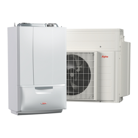
The Alpha E-Tec 33 Hybrid is a hybrid heat pump specifically designed to increase energy efficiency when replacing old
appliances, even on traditional radiator systems. Thanks to its compact size, it represents the ideal solution to easily install a
hybrid generator to replace an old gas boiler, with extremely easy installation and reduced installation time.
Composed of a 4 kW single-phase air/water mono block outdoor unit (with R32 coolant) and an indoor condensing gas boiler
connected hydraulically in series.
A control unit is also supplied as standard, to manage both boiler and heat pump. The smart logic, integrated in the system’s
electronics, is able to determine the most convenient energy source at that moment (heat pump or boiler) and therefore to
choose the source to be activated.
Operation in central heating takes place with the use of a heat pump and boiler, with the option of activating the two units at
the same time.
The complete 'package' consists of the following main components:
Outdoor unit with mono block heat pump, which mainly includes:
Swing-type rotary compressor with liquid separator, management electronics, lamination valve, finned coil for exchange with
external air (with single fan), external probe for sliding temperature operation, water/coolant gas heat exchanger, 3 bar water safety
valve, water side filter (already mounted inside the system return), anti-vibration feet. The supply also includes a thermostatic
antifreeze valve (which is only triggered in the absence of electricity, as the electronics include an antifreeze function with
activation of the pump and of the boiler if required), isolating valves for flow and return with vacuum breaker valve. The cooling
circuit is hermetically sealed (R32 coolant). Inertial buffer tank only required for systems with water content lower than 20 litres.
Wall-mounted indoor boiler unit which includes:
• Total pre-mixing combustion system with steel multigas cylindrical burner, complete with ignition electrode and ionisation
control, double shutter pneumatic gas valve.
• Gas/water primary heat exchanger with internal coil made of single-pipe Stainless steel, fanned for flue with electronically
variable speed.
• Condensate disposal including trap and flexible drain hose.
• Stainless steel water/water secondary heat exchanger for the production of domestic hot water.
• Hydraulic unit consisting of a 3-way valve, a 7 m modulating pump, a 3 bar safety valve, a flow switch for detecting domestic
hot water withdrawal, an 8 litre expansion vessel with 1.0 bar pre-charge and pressure gauge.
• System water flow/return and flue sensors.
• Control panel including: microprocessor P.C.B. with 3 sensor continuous flame modulation (1 DHW and 2 C.H.) with P.I.D.
control, modulation range from 4.3 to 33 kW .
• Electronic ignition with ionisation control, ignition delay device in central heating mode, anti-freeze protection system (standard
to -5 °C), pump anti-block device function, post-ventilation function, chimney sweep function and pump functioning mode
selection.
• Solar delay timing function for coupling with solar thermal systems, with the option of connecting a domestic hot water sensor
• Screed heater function.
• Self-diagnosis system.
• IPX5D electrical insulation rating.
• Sample points for combustion analysis, lower cover for connection group, gas and mains water isolation valves.
Control unit:
To manage boiler and heat pump, optimising the system in the most efficient way. A boiler mounted receiver and gateway unit
with bus connection via a cable between the outdoor and indoor units. Using a separate wireless controller with built in room
thermostat with App connection for smart phone remote user control.
2

Alpha E-Tec Hybrid - Safety Symbols
ELECTRICAL HAZARD
Strictly follow all of the indications next to the symbol. The symbol indicates the appliance’s electrical
components or, in this manual, identifies actions that can cause an electrical hazard.
SHARP SURFACES
The symbol indicates the appliance’s components or parts that can cause cuts if touched.
EARTH TERMINAL CONNECTION
The symbol identifies the appliance’s earth terminal connection point.
READ AND UNDERSTAND THE INSTRUCTIONS
Read and understand the appliance’s instructions before performing any operation, carefully following the
indications provided.
INFORMATION
Indicates useful tips or additional information.
SAFETY GLOVES
SAFETY GOGGLES
The user must not dispose of the appliance at the end of its service life as municipal waste, but send it to
appropriate collection centres.
GENERIC HAZARD
Strictly follow all of the indications next to the symbol. Failure to follow the indications can generate hazard
situations resulting in possible harm to the health of the operator and user in general.
PERSONAL PROTECTIVE EQUIPMENT
2 SAFETY SYMBOLS
3

3 TECHNICAL DATA
3.1 TECHNICAL PERFORMANCE DATA E-TEC 33 HYBRID BOILER
Alpha E-Tec Hybrid - Technical Data
Domestic hot water maximum heating power kW (kcal/h) 28.8 (24.773)
Central heating maximum heat input kW (kcal/h) 24.6 (21.194)
DHW maximum useful heat output kW (kcal/h) 28.3 (24.295)
CH maximum useful heat output kW (kcal/h) 24.1 (20.717)
Minimum nominal heat input kW (kcal/h) 4.5 (3.862)
Minimum nominal heat output kW (kcal/h) 4.3 (3.689)
Efficiency at 100% Pn (80/60°C) % 97.8
Efficiency at 30% of the load (80/60°C) % 102.3
Efficiency at 100% Pn (50/30°C) % 106.1
Efficiency at 30% of the load (50/30°C) % 108.3
Efficiency at 100% Pn (40/30°C) % 108.2
Efficiency at 30% of the load (40/30°C) % 108.3
Room central heating seasonal efficiency (ηs) % 93
Water heating energy efficiency (ηwh) % 87
Central heating circuit
Adjustable central heating temperature (min. / max) °C min. 20 - 50 / max 85
System max. working temperature °C 90
System max. working pressure bar 3
System expansion vessel nominal/(real) capacity litres 8.0 / (5.8)
System expansion vessel factory-set pressure bar 1.0
Minimum design system flow rate L/h 500
Head with 1000 l/h flow rate kPa (m c.a.) 40.6 (4.1)
Minimum system water content litres 20
DHW circuit
Hot water production useful heat output kW (kcal/h) 28.3 (24.295)
DHW adjustable temperature °C 30 - 60
Domestic hot water circuit min. dynamic pressure bar 0.3
Domestic hot water circuit / DHW Circuit max. pressure bar 8
D.H.W. min. withdrawal litres/min 1.5
Flow rate in continuous service (∆T 30°C) litres/min 13.7
Gas supply
Gas flow rate at METHANE burner (G20) MIN - MAX m3/h 0.48 - 2.61 (3.06 DHW)
Gas flow rate at LPG burner (G31) MIN - MAX kg/h 0.35 - 1.91 (2.25 DHW)
Electric power supply V/Hz 230 - 50
Nominal power absorption A 0.60
Installed electric power W 80
Power absorbed by pump max speed W 41
Power absorbed in stand-by W 2
Electric insulation rating IP X5D
Water content litres 2.2
Empty condensation unit weight kg 33.6
Effective efficiency at 100% output >93+2·log Pn
(Italian Lgs. D. 192/05 as amended) (Pn = 24.1 kW)
4

Alpha E-Tec Hybrid - Technical Data
Gas flow rates refer to the NHV at the temperature of 15° C and pressure of 1013 mbar.
Flue temperature values refer to an air inlet temperature of 15°C and flow/return temperature = 80/60°C.
Methane (G20) LPG (G31)
Combustion efficiency 100% Pn (80/60°C) % 97.8 97.8
Combustion efficiency P min (80/60°C) % 97.8 97.8
Effective efficiency at 100% Pn (80/60°C) % 97.8 97.8
Effective efficiency P min (80/60°C) % 95.5 95.5
Effective efficiency at 100% Pn (50/30°C) % 106.1 106.1
Effective efficiency P min (50/30°C) % 106.1 106.1
Effective efficiency at 100% Pn (40/30°C) % 108.2 108.2
Effective efficiency P min (40/30°C) % 108.3 108.3
Chimney losses with burner on (100% Pn) (80/60°C) % 1.7 1.7
Chimney losses with burner on (P min) (80/60°C) % 2.2 2.2
Chimney losses with burner off % 0.02 0.02
Casing losses with burner on (100% Pn) (80/60°C) % 0.2 0.2
Casing losses with burner on (Pmin) (80/60°C) % 2.3 2.3
Casing losses with burner off % 0.34 0.34
Flue gas temperature Maximum Heat Input °C 70 70
Flue gas temperature Minimum Heat Input °C 64 63
Flue flow rate at Central Heating Maximum Heat Input kg/h 38 37
Flue flow rate at Maximum Domestic Hot Water Heat Input kg/h 44 43
Flue flow rate at Minimum Heat Input kg/h 8 7
CO2at the Maximum Central Heating Heat Input % 9.70 11.40
CO2at Maximum Domestic Hot Water Heat Input % 9.70 11.40
CO2at Minimum Heat Input % 8.80 10.60
CO at Maximum Heat Input mg/kWh 321 316
CO at Minimum Heat Input mg/kWh 5 5
NOxat the Maximum Heat Input mg/kWh 59 85
NOxat Minimum Heat Input mg/kWh 34 55
Weighted CO mg/kWh 20 -
Weighted NOxmg/kWh 35 -
NOxclass - 6 6
Intake/exhaust available head (min-max flow rate) Pa 2 - 240
3.2 TECHNICAL PERFORMANCE DATA BOILER COMBUSTION FEATURES
5

Alpha E-Tec Hybrid - Technical Data
3.3 TECHNICAL PERFORMANCE DATA E-TEC EXTERNAL HEAT PUMP
Central heating circuit
Nominal power in CH mode with water set at 35 °C / Air 7 °C kW 3.98
Nominal power in CH mode with water set at 45 °C / Air 7 °C kW 3.80
Nominal power in CH mode with water set at 55 °C / Air 7 °C kW 3.32
Nominal power in CH mode with water set at 35 °C / Air 2 °C kW 2.97
Nominal power in CH mode with water set at 35 °C / Air -7 °C kW 3.53
Absorbed power in CH mode with water set at 35 °C / Air 7 °C kW 0.87
Absorbed power in CH mode with water set at 45 °C / Air 7 °C kW 1.15
Absorbed power in CH mode with water set at 55 °C / Air 7 °C kW 1.33
Absorbed power in CH mode with water set at 35 °C / Air 2 °C kW 0.79
Absorbed power in CH mode with water set at 35 °C / Air -7 °C kW 1.31
CH mode nominal COP with water set at 35 °C / Air 7 °C 4.55
CH mode nominal COP with water set at 45 °C / Air 7 °C 3.30
CH mode nominal COP with water set at 55 °C / Air 7 °C 2.50
CH mode nominal COP with water set at 35 °C / Air 2 °C 3.78
CH mode nominal COP with water set at 35 °C / Air -7 °C 2.70
CH flow temperature range °C 25 ÷ 55
Outdoor temp. limits for operation (DHW) °C - 15 ÷ 25 (35)
Heat pump general data
Electric power supply V/Hz 230/50
Permitted voltage range V 198 ÷ 264
Maximum absorbed power (outdoor condensing unit) W 2600
Fuse required / MCB A 16
Degree of protection IP X4D
C.H. sound power level dB(A) 59
Type of refrigerant / (GWP) R32 / 675
Refrigerant fluid load (R32) kg 0.56
Weight kg 45
Water content l 2.0
6

Alpha E-Tec Hybrid - General Information
4.1 ELECTRICAL SUPPLY
ATTENTION:
The boiler supply cable must be connected to a 230 V ±10% / 50 Hz mains supply respecting L - N
polarity and earth connection; , this must be connected to a fused 3 A double pole switch with class III overvoltage
category (contact separation of at least 3 mm in both poles) or a fused 3 A 3-pin plug and unswitched shuttered socket outlet
(both complying with BS 1363) in compliance with installation regulations.
The boiler is supplied with a 'Special X' type electrical connection with a PVC <HAR> H05VV-F 3 x 0.75 cable without a plug.
If the power cable is damaged or replaced, it must be replaced with a cable supplied by Alpha or authorized After-Sale
Technical Service. Replacement is recommended using a qualified company in order to prevent any risk.
The outdoor heat pump supply cable (not supplied) must be suitable for outdoor installation and must have at least a flexible
polychloroprene sheath (code IEC:60245 IEC 57 / CENELEC:H05RN-F).
The appropriate cable section can be 2.5 - 4 mm2, to be checked depending on the specific installation conditions.
The boiler and heat pump must be earthed.
Wiring external to the boiler must be in accordance with the current IEE Wiring Regulations (BS 7671).
If the boiler is locked out and an error code is shown on the display, the RESET button can be pressed to try and clear the fault.
If the fault still occurs after pressing the RESET button, then contact an approved engineer or Alpha service support department.
4.2 BOILER DIMENSIONS AND CONNECTIONS
F......... Flue centreline
C......... Condensate drain (min. internal Ø = 13 mm)
FL ....... System flow - 22mm
R......... System return - 22mm
G......... Gas - 22mm
MW ..... Mains inlet - 15mm
DHW... DHW outlet - 15mm
W........ Wiring entry point
Case top panel
440
220 220
252
135
30
65 70 95 95 70 45
275 268
120
11
8
36
25
687
748
WRFL
GDHW MW
C
R
FL
MW
DHW
G
FF
Fig. 4.1
4 GENERAL INFORMATION
Outdoor E-Tec heat pump Nominal Values Field of Tolerable
Voltage
Maximum absorbed current
(MAC) in normal operation
Supply fuse/MCB required
for Control (100mA RCD)
Hz V V V A A
50 220 - 240 198 264 10.3 16
Boiler power supply BUS Communication cable
between outdoor heat pump and
Control panel
Power supply Max./Min.(V) Connection cable
220-240V AC, 50Hz ±10% 0,75 - 1.5 mm², 3 core 0.75 - 1.5mm², 2 core (shielded)
7

87 574 185
12
558 70
845
35
8
126 350
311
285 44
745
25
681
FR
F R
MHT RHT
Alpha E-Tec Hybrid - General Information
4.3 EXTERNAL HEAT PUMP DIMENSIONS AND CONNECTIONS
R.... Return to heat pump = 28mm
F.... Flow from heat pump = 28mm
The heat pump unit is supplied with Flow
and Return isolating valves and anti-
vibration mounts.
Fig. 4.2
4.3 GRUNDFOS UPM4 PUMP SETTINGS
The indoor boiler is equipped with a low power consumption pump with variable speed regulator, the pump also works for the
heat pump, since the two generators are placed in series with each other.
The pump speed is set using the parameters present in the Assistance Menu -> System Definition of the Control panel.
For the hybrid heat pump to work properly, it is not allowed to drop below the minimum value indicated in Fig. 4.3.
In domestic hot water mode, the pump always runs at full speed. The pump speed settings should not be adjusted.
NOTE: The boiler is supplied with the by-pass closed.
For correct operation of the system, the boiler by-pass must be kept closed.
It is essential for correct operation that a branch of the system always remains open; otherwise it will be required to
install an external by-pass (especially in the case of zone valves or thermostatic valves on the radiators) the purpose
is to allow the antifreeze function to be carried out (which occurs when the pump is restarted).
For proper system operation, make sure that the minimum flow rate in operating conditions never drops below 500 l/h.
An inline filter must be fitted in the return to the heat pump.
Treating the system water allows you to prevent problems and maintain the function and efficiency of the boiler over time.
Chemical treatment of the thermal system water, must be in compliance with the BS 7953.
NOTE: To ensure correct operation of the heat pump a minimum water content in the system is required, which must be 20
litres for all kinds of systems.
So attention must be paid to the systems spread over several zones, where the water content available to the unit changes
continuously.
MHT..... Flow from heat pump
RHT ..... Return to heat pump
8

Fig. 4.3
A= Head available to boiler
B= Power absorbed by the pump (dotted area)
Alpha E-Tec Hybrid - General Information
10
20
30
40
50
60
70
80
0
1
2
3
4
5
6
7
8
0 200 400 600 800 1000 1200 1400
0
Head (m water)
Flow rate (l/h)
Pump electrical consumption (W)
AB
Speed 9
Speed 5
Available head to boiler
4.4 AVAILABLE PUMP HEAD AND POWER CONSUMPTION
Total head available to the system.
To obtain the available head for the system, subtract the head losses of the outdoor heat pump from the available head of the
boiler.
Fig. 4.4
4.5 OUTDOOR HEAT PUMP HEAD LOSS
The resistance of the hydraulic circuit of the outdoor heat pump must be taken into account when calculating the flow rate and
head values available to the system.
The graph, Fig. 4.4, shows the resistance (pressure drops) of the outdoor heat pump circuit as the system flow rate varies.
For the correct connection of the outdoor unit, refer to the E-Tec EHP instructions.
Head losses (m water)
Flow rate (l/h)
0
0.5
1.0
1.5
2.0
2.5
3.0
3.5
4.0
4.5
5.0
0 200 400 600 800 1000 1200 1400 1600
9

4.6 SYSTEM HYDRAULIC DIAGRAM
1.......... Alpha hybrid boiler (indoor unit)
2.......... Alpha heat pump (external unit)
3.......... Smartech boiler mounted receiver
4.......... Domestic hot water inlet isolating valve
5.......... Gas isolating valve
6.......... Heat pump flow isolating valve with vent
7.......... Heat pump return isolating valve with vent
8.......... Heating system
9.......... Smartech thermostat controller
10 ........ Magnetic system filter (not supplied)
Fig. 4.5
Alpha E-Tec Hybrid - General Information
1
7
5
6
4
2
3
9
Alpha
CLOUD
BUS
BLE
RESET
PWR
MHT RHT
G
DHW
MW
GDHW MW RF
OD
10
8
20.°
21.5
15°
4
FRI 12:08
NOTE: This diagram is an example. It is also required to convey the condensate drain of the heat pump and boiler.
NOTE: System minimum water content:
To ensure correct operation of the heat
pump it is necessary to maintain a minimum
water content in the system equal to 20
litres, for any type of system, it is also
necessary to have a loop that is always
open on the system to allow the heat pump
to perform the antifreeze function.
Maximum length of pipe
between the heat pump
flow and boiler return 10 m
All main pipework for flow and return
between the heat pump, boiler and
radiator distribution circuit must be a
minimum of 22mm.
G.......... Gas supply
DHW.... Domestic hot water outlet
MW ...... Mains water inlet
C.......... Condensate drain
F.......... System flow
R.......... System return
MHT..... Flow from heat pump
RHT ..... Return to heat pump
OD ....... Outdoor unit water drain
10

Note: This Appliance Must Be Earthed
4.7 ELECTRICAL CONNECTIONS
Fig. 4.7
A23 ....Alpha external heat pump
A30 ....Smartech boiler receiver
B9 ......DHW inlet sensor (optional)
R........120 Ohm resistor
1........Power supply
2........Configurable relay
The connection between the boiler and the external heat pump must be made as shown in Figs. 5.14 and 5.15.
Specifically, a connection (2 BUS cables) must be provided between the Smartech boiler receiver unit and the external heat
pump, observing the polarity. The receiver must also be connected (4 wires) to the terminal board of the boiler.
The fitting and connection of the receiver (Fig.4.8) is necessary for the operation of the hybrid heat pump and for programming
its settings.
Alpha E-Tec Hybrid - General Information
A23 A30
B9
Max 2A - 230 VAC
230V AC
50 Hz Configurable
output
LN
LNAB
2
561
1
2
44 41 38 48
X3 D-
X3 D+
X2 OT
X2 OT
X1 Bl
X1 Br
D-
D+
R
BUS
CLOUD
PWR
BLE
RESET
Br Bl
Power pack
Receiver
Fig. 4.8
11

4.8 BOILER SCHEMATIC
1 Gas isolation valve
2 Cold mains isolation valve with
integrated filling valve
3 Gas valve
4 DHW flow switch
5 Gas injector
6 Flow regulator
7 DHW temperature sensor
8 Condensate trap
9 3 bar safety valve
10 Expansion vessel
Fig. 4.9
11 Venturi positive pressure point (+)
12 Venturi
13 Primary flow temperature sensor
14 Ignition/sensing electrode
15 Air supply pipe
16 Flue temperature sensor
17 Flue test point (pressure point +)
18 Air test point (pressure point -)
19 Burner
20 Primary return sensor
21 Fan
22 Automatic air vent
23 Boiler pump
24 Primary pressure switch
25 DHW heat exchanger
26 Diverter valve
27 By-pass
28 Drain point
29 Safety valve indicator
30 Filling loop
31 Heating return isolation valve
with integrated filling valve
32 Heating flow isolation valve
Gas
Condensate discharge
and expansion relief
Primary return
connected to
E-Tec
EHP flow Primary flow
to Heating
system
Domestic
hot water
outlet
Cold mains
water inlet
1
2
3
4
5
6
7
8
9
10
32
31
30
29
28
27
26
25
24
23
22
21
20
19
18
11
12
13
14
15
16 17
Alpha E-Tec Hybrid - General Information
12

Alpha E-Tec Hybrid - General Information
Fig. 4.10
4.9 HEAT PUMP SCHEMATIC
R..............Return to heat pump
F..............Flow from heat pump
b1.............Stop valve (cooling liquid)
b2.............Stop valve with service opening (coolant gas)
c...............Silencer
d...............Silencer with filter
e...............Heat exchanger
f................Storage tank
g...............Safety valve
h...............Cut-off valve
i................Air purge
j................Cap
k...............Antifreeze protection valve
l................Vacuum switch
m..............Filter
B1PR .......Coolant pressure sensor
Shut-off valve... Standard supplied shut-off valves
M1C.........Compressor motor
M1F .........Fan motor
R1T..........External probe
R1T (t>) ...Water outlet probe
R2T..........Evaporator probe
R3T..........Compressor outlet probe
R3T (t>) ...Liquid phase probe
R4T (t>) ...Water inlet probe
S1PH .......High pressure switch
Y1E..........Electronic expansion valve
Y1S..........Four way solenoid
........Screw connection
........Flared connection
........Quick release connector
Shut off valves
S1PH
R3T
t>
R1T
t>
R4T
t>
R1T
(*)(**) OR
(***)(****)
(*)
(**)
(*) OR
(**) OR
(***) OR
(****)
(***)
(****)
R2T
R3T
B1PR
M1C
Y1S
M1F
Y1E
b1
d
e
e
d
i
R
F
d
b2
g
h
j
k
c
c
f
cm
(***) (*)
(****) (**)
h
ii
i
i
h
l
l
Shut off valves Shut off valves
13

Alpha E-Tec Hybrid - General Information
Fig. 4.11
1 Expansion vessel
2 Burner
3 Viewing window
4 Ignition/sensing electrodes
5 Air supply pipe
6 Primary flow temperature sensor
7 Fan
8 Condensate trap
9 DHW flow switch
10 Gas injector
11 Gas valve
12 DHW heat exchanger
13 Boiler drain point
14 DHW temperature sensor
15 Test points (air A, flue F)
16 Flue temperature sensor
17 Four fixing nuts for item 18
18 Combustion chamber front assembly
19 Primary heat exchanger
20 Venturi
21 Primary return temperature sensor
22 Primary pressure switch
23 Automatic air vent
24 Boiler pump
25 3 bar safety valve
26 By-pass
27 Diverter valve
28 Safety valve operation indicator
4.10 BOILER MAIN COMPONENTS
2
12
13
7
6
11
14
1
4
5
8
9
10
3
16
19
20
21
22
23
24
25
26
27
15
AF
17
18
28
14

Alpha E-Tec Hybrid - Installation of Heat Pump
5 INSTALLATION OF HEAT PUMP
The place of installation of the heat pump is very important and must be established by the system designer or by a
specifically qualified person, and must take into account the technical requirements, standards and regulations in force.
The heat pump unit must only be installed outside the building.The boiler unit must only be installed inside the building.
It is recommended to avoid:
Positioning near windows.
Obstacles or barriers that cause recirculation of exhaust air.
Places with aggressive atmospheres.
Limited spaces or places where sound levels from the unit can be enhanced through reverberations or resonance.
Positioning in corners where there is an accumulation of dust, leaves and anything else that can reduce the efficiency of the
heat pump.
Prevent exhaust air from the unit from coming into the rooms through doors or windows.
The heat pump must:
Be placed on a level surface that is able to withstand its weight.
Be placed on a slab that is hard enough and which does not transfer any vibrations to the underlying or adjacent rooms.
In any case, provide a space of at least 100 mm under the unit (to avoid operating problems in the event of heavy snow).
Where there is a risk of snow build up or leaves increase the clearance.
Use the vibration-dampening supports supplied with the unit.
The effects of the wind can be minimised by installing the unit with the intake side facing a wall.
The unit must not be installed with the intake side against the prevailing wind.
The effects of the wind can be further minimised by installed a deflector plate facing the unit air flow side (not supplied).
Be at least 1m distance from any part of the outdoor unit and property boundary.
With the back side of the unit
facing a wall
With two sides of the unit
facing a side and rear wall
With three sides of the unit
facing a wall
With two sides of the unit
facing a side and front wall
a- Air outlet
b- Air inlet
With the front side of the unit
facing a wall
5.1 MINIMUM INSTALLTION CLEARANCES
>250
(mm)
b
>350
>250
a
b
>250
>350
a
b
>250
>350
a
b
>250
a
b
a
>250
>100
Fig. 5.1
15

Alpha E-Tec Hybrid - Installation of Heat Pump
a- Snow cover or shelter
b- Pedestal
c- Prevailing wind direction
d- Air outlet
NOTE: The clearances shown in Fig. 5.1 must be left free to allow air to circulate and to ensure accessibility
for repairs or maintenance on every side of the heat pump. In fact, it must be possible to disassemble all the
components under the utmost safety conditions (both for objects and for people).
If the heat pump is to be installed in regions subject to heavy snow:
It will be necessary to raise the unit by at least 100 mm above the maximum expected snowfall or, alternatively, use wall-support
brackets, see Fig. 5.5 (optional) to protect the unit from direct snowfall and take care that the unit is NEVER buried under snow.
The unit must be installed in a position protected from snow falling from above.
If this is not possible, you must at least prevent the snow from clogging the air/coolant exchanger (even by constructing a
small protective roof for the heat pump, if necessary. See Fig. 5.3).
If blowing lateral snowfalls are possible, make sure that the heat exchanger coil CANNOT be covered by snow.
574
311
<100
0
0
1
>
(mm)
c
a
b
c
d
d
<150
a
0
5
1>
311
574
001>
(mm)
(mm)
a
4×
>300
Fig. 5.2
Fig. 5.3
Fig. 5.4 Fig. 5.5
a- Anti-vibration rubber
5.2 POSITIONING THE HEAT PUMP
16

Alpha E-Tec Hybrid - Installation of Heat Pump
5.3 CONDENSATE DRAINAGE
If the condensate produced is drained through the drain pipe, connect the drain fitting (cin Fig. 5.6) supplied as
standard to the drain pipe (din Fig. 5.6) (not supplied) with an internal diameter of 16 mm.
If the installation is in a very cold area or where heavy snow is likely and there is the possibility that the condensate might freeze,
an optional trace heating kit for the outdoor unit is available which gives anti-freeze protection on the outdoor unit up to -15 °C.
NOTE: If the condensate water produced by the unit is not properly drained, the performance of the entire system will suffer a
negative impact and the system itself could be damaged.
a- Drain hole
b- Lower frame
c- Drain fitting (supplied as standard)
d- Flexible hose (not supplied)
b
c
d
a
Fig. 5.6
5.4 THERMOSTATIC ANTIFREEZE VALVE
The E-Tec Hybrid is equipped with a system that protects it against freezing thanks to the periodic start-up of the
pump and, if necessary, activation of the boiler unit.
If the outdoor unit is installed in areas where the temperature might fall below 0°C, it is recommended to provide
special antifreeze systems in order to guarantee the units integrity, especially the water-gas heat exchanger, when
there is a power cut.
For example, insert an appropriate quality, non-hazardous antifreeze liquid into the heating system. In this case, the
instructions of the manufacturer of this liquid must be followed scrupulously regarding the percentage necessary with respect
to the minimum temperature at which the system must be kept.
An aqueous solution must be made with potential pollution class of water 2 (EN 1717:2002).
NOTE: In cases where you do NOT wish to introduce antifreeze glycol into the system, the outdoor unit is equipped with a
thermostatic antifreeze valve (supplied as standard, but to be installed as shown in Fig. 5.7), which intervenes when the water
temperature detected inside the heat pump drops below 3 to 4°C, allowing the water inside the machine to be drained. The
water drain is directed towards the condensate collection tank located in the lower part of the heat pump.
ATTENTION: Using the thermostatic antifreeze valve is an alternative to the solution of introducing antifreeze glycol
into the circuit.
(a+b1)
(b2)
2×
1
4×
3
2×
2
2×
Fig. 5.7
Refer to Fig. 5.7 and remove the covers to gain access to
fit the freeze protection valve and vacuum breaker.
1Remove the fixing screws and remove the top cover.
2Remove the fixing screws and remove the front cover.
3Remove the fixing screws and remove the rear cover.
a- Connection piece for b1
b1- Freeze protection valve (for water drainage)
b2- Vacuum breaker
17

Alpha E-Tec Hybrid - Installation of Heat Pump
NOTE: In addition to the thermostatic antifreeze valve, a vacuum breaker valve is also supplied, which must be installed on the
heat pump delivery valve (flow from the heat pump, F in Fig. 5.2) by removing the cap present in the valve and replacing it with
the vacuum breaker as shown in Fig. 5.13.
1 2 3
b2
1Remove the clip.
2Remove and discard the
stop with sealing washer.
3Attach the freeze
protection valve (b1) to
the connection piece (a),
using thread sealant.
4Attach the connection
piece to the heat pump
unit.
5Replace the clip.
6Replace the rear, front
and top covers.
12
a
b1
Fig. 5.8
Fig. 5.9
Fig. 5.10
Fig. 5.11
Fig. 5.12
Fig. 5.13
18

Alpha E-Tec Hybrid - Installation of Heat Pump
Q1D1 ....Isolator switch
Refer to Sections 4.1and 4.7 for further wiring details.
1. Connect the power supply cable (shown in Fig. 5.14) to the heat pump terminal block X2M and secure in position with the
4 cable ties.
2. Connect the Smartech boiler receiver unit (ashown in Fig. 5.15) to the heat pump (terminal block X5M terminals 2 and 3)
and secure in position with the cable tie.
1×
X2M
Vbus 0- 0+ GND
P1 P2
a
X5M
2
3
D-D+
220-240V
ac 50Hz
16A MCB
ENL
Q1DI
123 LN
1×
Fuse
20A
3×
X2M
Vbus 0- 0+ GND
P1 P2
Fig. 5.14 Fig. 5.15
5.5 CONNECT THE HEAT PUMP WIRING
The outdoor unit power cable (not standard supplied) must be suitable for outdoor installation and must have at least a flexible
polychloroprene sheath (code IEC:60245 IEC 57 / CENELEC:H05RN-F). Indicatively, the appropriate cable section can be 2.5
x 4 mm2, to be checked depending on the specific installation conditions.
Outdoor Unit Nominal Values Field of Tolerable
Voltage
Maximum absorbed
current (MAC) in
normal operation
Supply fuse/MCB
required (a) 100mA
RCD
Power supply
cable
Hz V V V A A
E-Tec external
heat pump 50 220-240 198 264 10.3 16 2.5 mm², 3 core
For the connection between outdoor and indoor units usese H07RN-F or H05RN-F class cables to power the indoor unit.
Indoor gas boiler power supply BUS Communication cable
between outdoor unit and Control
panel
Power supply Max./Min.(V) Connection cable
Single phase,
220-240V, 50Hz ±10% 1.5 mm², 3 core 0.75 mm², 2 core
19

Alpha E-Tec Hybrid - Operating Principals
The E-Tech Hybrid control logic establishes various operating situations described below:
CENTRAL HEATING MODE
When operating in winter heating mode the operating logic between the boiler and heat pump can be selected between 2 options:
•Withxedexternalswitchingtemperature(“MANUAL”mode).
• Withvariableexternalswitchingtemperatureaccordingtotheelectricityandgascosts(“AUTO”mode).
OPERATION IN ROOM HEATING MODE (MANUAL MODE):
Following a request in the room heating phase, if an external switching temperature between boiler and "manual" heat pump is set in the
Control panel menu, below this temperature (example +5 °C) only the boiler is activated, above this temperature the heat pump always starts
and if the set delivery time is not reached in the waiting time (which can be set in the specific parameter menu), the boiler is also activated, in
series and simultaneously.
OPERATION IN ROOM HEATING MODE (AUTOMATIC MODE):
With automatic operation, the specific menu includes the costs of electricity and gas through which the electronics calculate a convenience
COP; based on the detected external temperature and the calculated flow set, the boiler (COP lower than the convenience COP) or the heat
pump (COP greater than or equal to the convenience COP) are activated.
Also in the latter case, if in the waiting time (which can be set in the specific parameter menu) you do not reach the set delivery set, the boiler
is also activated, in series and at the same time.
Simultaneous operation significantly increases the number of hours in which the heat pump is active in the heating period: for most of the time
the heating request is satisfied by the heat pump alone or by the hybrid operating mode.
NOTE: Depending on the outdoor temperature, for a flow temperature higher than 55 °C, the boiler is activated directly.
In“automatic”modevaluesTe1andTe2aredeterminedbythesystemlogic
(by setting the "manual" mode, the value "Te2" corresponds to the value of "Te1" + 5 °C)
6 E-TEC HYBRID OPERATING PRINCIPALS
Funzionamento
unità esterna
Se dopo il tempo di
attivazione non si
raggiunge la temperatura
impostata parte
anche l’unità interna
Set Risc
55 °C
Temp
esterna
Te2 25 °CTe1-25 °C
Funzionamento
esclusivo dell’
unità a condensazione
85 °C
25 °C
Funzionamento
unità esterna
Se dopo il tempo di
attivazione non si
raggiunge la temperatura
impostata parte
anche l’unità interna
Exclusive operation
of the boiler indoor
unit
Outdoor unit
operation
e indoor unit
also starts if the set
temperature is not
reached aer the
activation time
Outdoor unit
operation
e indoor unit
also starts if the set
temperature is not
reached aer the
activation time
External
temp
CH Set
Fig. 6.1
20
Table of contents
Other Alpha Heat Pump manuals
Popular Heat Pump manuals by other brands

nilan
nilan Compact P user manual

COMFORTPOOL
COMFORTPOOL ECO+3 Installation instructions manual

Bosch
Bosch Compress 3400i AWS Operation manual

Bryant
Bryant LEGACY 223A installation instructions

Emicon
Emicon R-PAE Use and maintenance manual

Carrier
Carrier 38CQ Installation, Start-Up and Service Instructions

Trane
Trane IC-IH 039 Installation operation & maintenance

Sharp
Sharp AY-ZP35PR Service manual

LG
LG MULTI V ARNU-GVE Series owner's manual

York
York YAP026 installation manual

Viessmann
Viessmann Vitocal 242-S Installation and service instructions

ECOFOREST
ECOFOREST ecogeo hp Installation and operating manual