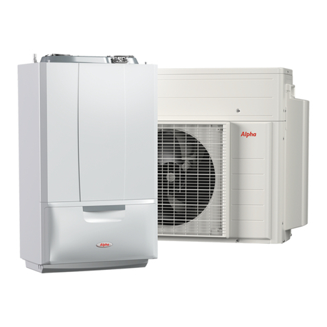
Alpha Hydro Heat Pump
CONTENTS
General warnings ....................................................................... 3
Safety symbols used.................................................................... 5
Personal protective equipment................................................. 5
1 Product specications. .................................................. 6
1.1 Product range. ................................................................ 6
1.2 Accessories...................................................................... 6
2 Outdoor unit specications.......................................... 7
3 Main components .......................................................... 8
4 Installing the unit.........................................................10
4.1 Outdoor unit installation position.............................10
4.2 Installation guide near the sea....................................10
4.3 Preparation of re extinguisher.................................. 12
4.4 Free ignition sources....................................................12
4.5 Ventilation of the area. ................................................12
4.6 Leak detection methods..............................................12
4.7 Labelling........................................................................12
4.8 Recovery. .......................................................................12
4.9 Installation place requirements.................................. 12
4.10 Moving the outdoor unit with wire ropes.................13
4.11 Clearance requirements for the outdoor unit. .........13
4.12 Installing the outdoor unit..........................................14
4.13 Mount of outdoor unit. ...............................................14
4.14 Drain..............................................................................15
4.15 Positioning the unit in a rigid climate.......................17
5 Electrical connections. ................................................18
5.1 General conguration of the system. ........................18
6 Connecting the cable...................................................19
6.1 Power supply cable specications..............................19
6.2 Specications of single-phase terminal block. ......... 19
6.3 Power cable connection diagram...............................20
6.4 Connection of power terminal...................................22
6.5 Installation of earthing wire. ......................................23
6.6 How to connect power supply extension cables. ..... 24
7 Proper earthing check. ................................................26
8 Pipe implementation. .................................................27
8.1 Air wash and purge......................................................27
8.2 Head losses of the outdoor unit based on glycol
concentration................................................................ 30
8.3 Water loading. ..............................................................32
8.4 Pipe insulation.............................................................. 32
9 Cooling cycle diagram. ...............................................33
10 Wiring diagrams. .........................................................34
10.1 HYDRO 5 wiring diagram..........................................34
10.2 HYDRO 8 wiring diagram..........................................35
10.3 HYDRO 12 and 16 wiring diagram...........................36
11 Micro-switch settings and key functions. ................37
11.1 HYDRO 5 testing operations. ....................................37
11.2 HYDRO 8 -16 testing operations...............................38
12 Maintenance. ................................................................41
12.1 Adding refrigerant. ......................................................41
12.2 Precautions on adding refrigerant R-32....................42
13 Charging the refrigerant..............................................43
13.1 Important information: used refrigerant regulation.43
14 Completing installation...............................................44
15 Final inspections and test operation..........................45
15.1 Inspection prior to test operation..............................45
15.2 Test operation. ..............................................................45
Correct disposal of the product
(Waste electrical and electronic equipment)(Applicable in Countries with separate waste collection systems)
When this symbol is applied on the product, on the accessories or on its documentation, it means that the product and relative electronic
accessories must not be disposed of with other waste at the end of its life cycle. To avoid damaging the environment or health due to incorrect
waste disposal, the user is recommended to separate the product and the above-mentioned accessories from other types of waste and to recycle
them responsibly by sending them to authorised facilities in compliance with local standards.
Household users are encouraged to contact the dealer where they purchased the product or the competent authorities to receive all of the
information regarding the separate waste collection of these products so that they may be disposed of properly without harming the environment.
Corporate users should contact their supplier and verify the terms and conditions of the purchase contract. is product and relative electronic
accessories must not be disposed of together with other commercial waste
2


