5
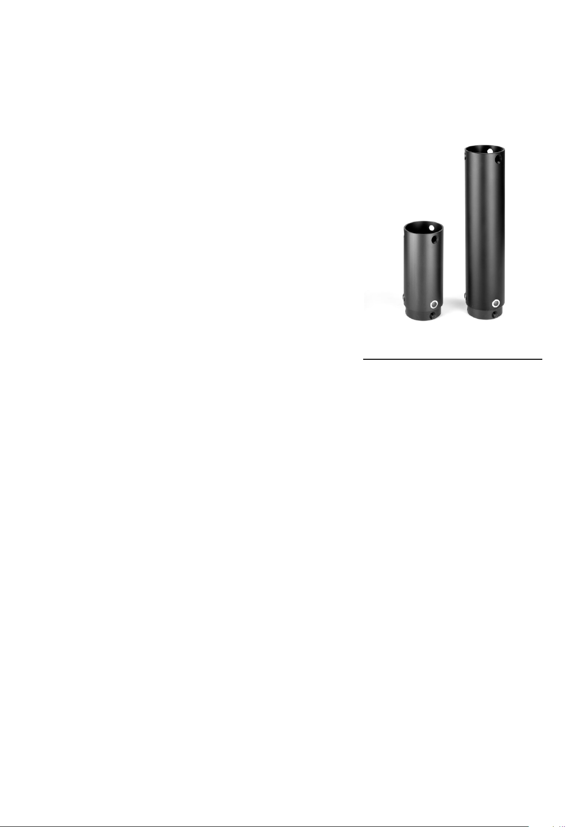
3B EXTENDED SET-UPS (optional):
The Pedestal can be enlarged using the optional extension 150 and 300. For sitting work the
above described set-up will do. For standing, depending on the length of the user the extensions
are used.
Placing Extensions:
- Remove the three Locking Screws (22) that hold the
column in the Base Piece (21) using the supplied hexagon
key.
- Take off the Column with spider and lay it aside.
- Mount the extension(s) you need using the same
hexagon key. Fix them firmly but do not use too much
force for there is a chance of damaging the tool or the
screws.
- Take the Column and mount it on top of the
extension(s).
- Lower the Tensioning Pens (13)
- Loosen the Spider Clamp Ring (9) with the two locking
screws and let it slide down until the spider legs fit the
Tensioning Pens. Then fasten the Spider Clamp Ring
again with both screws.
- Tension the Spider using the Tension Pens (counter
clockwise).
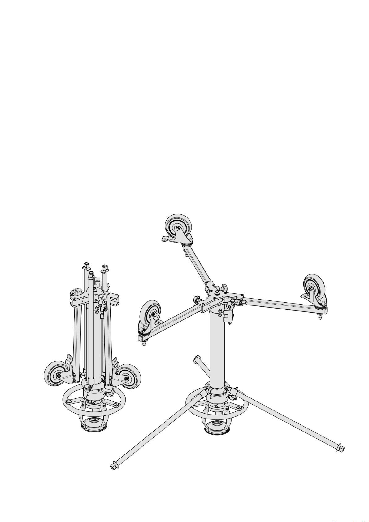
3C LOW SET-UPS:
- Remove the three locking screws (5) that hold the Bowl Unit on the inside column (6) using the
supplied hexagon key.
- Take off the Bowl Unit and lay it aside.
- Remove the three locking screws (22) that hold the column in the base piece (21) using the
supplied hexagon key.
- Take off the Column with spider and lay it aside.
- Mount, if necessary the extension you need using the same hexagon key. Fix them firmly but do
not use too much force for there is a chance of damaging the tool or the screws.
- Take the Bowl unit and mount it on top of the extension(s) or directly to the Base Piece (21) of
the Dolly.
- A special low set up is possible using only the Bowl unit, placing it on its rubber feet on the
ground or a table.