manuals.online logo
Brands
  1. Home
  2. •
  3. Brands
  4. •
  5. Alpine
  6. •
  7. GPS
  8. •
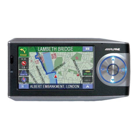
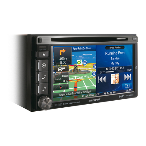
  9. Alpine INA-W910R User manual

Alpine INA-W910R User manual

YAMAGATA (Wuxi) Co., Ltd.
Block 28-25,Changjiang Nanlu, WND, jiangsu, China
Designed by ALPINE Japan
Printed in China (Y)
68-16909Z55-A
EN
DE
FR
01INA-W910R-IM.fm
ES
IT
SE
NL
RU
PL
GR
ALPINE INA-W910R 68-16909Z55-A (EN/DE/FR)
ADVANCED NAVI STATION
INA-W910R
INSTALLATION MANUAL INSTALLATIONSHANDBOK
INSTALLATIONSANLEITUNG INSTALLATIEHANDLEIDING
GUIDE D’INSTALLATION РУКОВОДСТВО ПО УСТАНОВКЕ
MANUAL DE INSTALACIÓN INSTRUKCJA MONTAŻU
MANUALE DI INSTALLAZIONE ΕΓΧΕΙΡΙΔΙΟ ΕΓΚΑΤΑΣΤΑΣΗΣ
00INA-W910R-IM.book Page 1 Thursday, March 3, 2011 3:15 PM
02INA-W910R-IMTOC.fm
IMPORTANT
Please record the serial number of your unit in the space provided below and
keep it as a permanent record.
WICHTIG!
Notieren Sie sich die Seriennummer des Geräts bitte an der unten angegebenen
Stelle und bewahren Sie die Notiz auf.
IMPORTANT
Notez le numéro de série de l’appareil dans l’espace prévu ci-contre et
conservez-le.
SERIAL NUMBER:
INSTALLATION DATE:
INSTALLATION TECHNICIAN:
PLACE OF PURCHASE:
SERIENNUMMER:
EINBAUDATUM:
EINGEBAUT VON:
GEKAUFT BEI:
NUMÉRO DE SÉRIE :
DATE D’INSTALLATION :
INSTALLATEUR :
LIEU D’ACHAT :
1
ALPINE INA-W910R 68-16909Z55-A (EN/DE/FR)
Contents / Inhalt / Contenu
Specifications / Technische Daten /
Caractéristiques techniques ..................................... 2
Installation / Einbau / Installation ........................... 4
Connections / Anschlüsse / Raccordements .......... 10
00INA-W910R-IM.book Page 1 Thursday, March 3, 2011 3:15 PM
2
03INA-W910R-IM.fm ALPINE INA-W910R 68-16909Z55-A (EN/DE/FR)
MONITOR SECTION
Screen Size 7.0"
Number of Picture
Elements
1,152,000 pcs.
(800 × 3 × 480)
FM TUNER SECTION
Tuning Range 87.5 - 108.0 MHz
MW TUNER SECTION
Tuning Range 531 - 1,602 kHz
LW TUNER SECTION
Tuning Range 153 - 281 kHz
NAVIGATION SECTION
Received Frequency 1.57542 ±1.023 MHz
Receiving Sensitivity -130 dBm
GENERAL
Power Requirement 14.4 V DC
(11-16 V allowable)
Maximum
Power Output 50 W × 4
Weight 2.7 kg (5 lbs. 15 oz)
MONITOR
Bildschirmgröße 7,0"
Anzahl Bildelemente 1.152.000 Pixel
(800 × 3 × 480)
UKW-TUNER
Empfangsbereich 87,5 – 108,0 MHz
MW-TUNER
Empfangsbereich 531 – 1.602 kHz
LW-TUNER
Empfangsbereich 153 – 281 kHz
NAVIGATION
Empfangsfrequenz 1,57542 ±1,023 MHz
Empfangsempfindlichkeit -130 dBm
ALLGEMEINES
Spannungsversorgung 14,4 V
Gleichspannung
(11 – 16 V zulässig)
Max. Ausgangsleistung 50 W × 4
Gewicht 2,7 kg (5 lbs. 15 oz)
SECTION DU MONITEUR
Taille de l’écran 7,0"
Nombre d’éléments
d’image
1 152 000 pixels
(800 × 3 × 480)
SECTION DU TUNER FM
Plage d’accord 87,5 – 108,0 MHz
SECTION DU TUNER MW
Plage d’accord 531 – 1 602 kHz
SECTION DU TUNER LW
Plage d’accord 153 – 281 kHz
SECTION NAVIGATION
Fréquence recue 1,57542 ±1,023 MHz
Sensibilité de reception -130 dBm
GÉNÉRALITÉS
Puissance requise
14,4 V CC
(11-16 V admissibles)
Puissance de sortie
maximum 50 W × 4
Poids 2,7 kg
Specifications / Technische Daten /
Caractéristiques techniques
00INA-W910R-IM.book Page 2 Thursday, March 3, 2011 3:15 PM
3
03INA-W910R-IM.fm ALPINE INA-W910R 68-16909Z55-A (EN/DE/FR)
CHASSIS SIZE (Monitor section)
Width 178 mm (7")
Height 100 mm (3-15/16")
Depth 164.6 mm (6-1/2")
BLUETOOTH SECTION
BLUETOOTH
Specification Bluetooth V2.0
Output Power +4 dBm Max.
(Power class 2)
Profile HFP (Hands-Free
Profile)
HSP (Head Set
Profile)
REMOTE CONTROL
Battery Type CR2025 battery
Width 51 mm (2")
Height 119 mm (4-11/16")
Depth 13 mm (1/2")
Weight 40 g (1.4 oz)
(battery excluded)
GEHÄUSEGRÖSSE (Monitor)
Breite 178 mm
Höhe 100 mm (3-15/16")
Tiefe 164,6 mm (6-1/2")
BLUETOOTH
Technische Daten für
BLUETOOTH Bluetooth V2.0
Ausgangsleistung +4 dBm Max.
(Leistungsklasse 2)
Profil HFP (Hands-Free
Profile)
HSP (Head Set
Profile)
FERNBEDIENUNG
Batterietyp CR2025-Batterie
Breite 51 mm (2")
Höhe 119 mm (4-11/16")
Tiefe 13 mm (1/2")
Gewicht 40 g (1,4 oz)
(ohne Batterie)
DIMENSIONS DU CHÂSSIS
(Section du moniteur)
Largeur 178 mm
Hauteur 100 mm
Profondeur 164,6 mm
SECTION DU DISPOSITIF BLUETOOTH
Spécifications
BLUETOOTH Bluetooth V2.0
Puissance de sortie +4 dBm max.
(classe 2)
Profil HFP (profil mains
libres)
HSP (profil casque)
TÉLÉCOMMANDE
Type de pile Piles CR2025
Largeur 51 mm
Hauteur 119 mm
Profondeur 13 mm
Poids 40 g
(pile non comprise)
00INA-W910R-IM.book Page 3 Thursday, March 3, 2011 3:15 PM
4
03INA-W910R-IM.fm ALPINE INA-W910R 68-16909Z55-A (EN/DE/FR)
•When making connections to the vehicle’s electrical
system, be aware of the factory installed components (e.g.
on-board computer). Do not tap into these leads to
provide power for this unit. When connecting the
INA-W910R to the fuse box, make sure the fuse for the
intended circuit of the INA-W910R has the appropriate
amperage. Failure to do so may result in damage to the
unit and/or the vehicle. When in doubt, consult your
ALPINE dealer.
•The Display must be completely retracted in the casing
when installing. If it is not, problems may occur.
1
When installing in automobiles, make sure the
Display can open/close without coming in
contact with the shift lever.
Movable Display
•Beim Anschließen an das Bordnetz des Fahrzeugs
unbedingt die werkseitig eingebauten Komponenten (z. B.
Bordrechner) beachten. Keinesfalls die Stromversorgung
für das Gerät an diesen Komponenten abgreifen. Beim
Anschluss im Sicherungskasten des INA-W910R darauf
achten, dass die Sicherung des gewählten Stromkreises
die für den INA-W910R vorgeschriebene Amperezahl
aufweist. Bei Nichtbeachtung dieses Punktes sind
Folgeschäden am Gerät bzw. am Fahrzeug nicht
ausgeschlossen. Im Zweifelsfall gibt Ihr ALPINE-
Fachhändler gerne Auskunft.
•Der Monitor muss beim Einbau ganz eingefahren sein.
Wenn er offen steht, können Einbauprobleme auftreten.
1
Das Gerät muss so ins Fahrzeug eingebaut
werden, dass das Display sich ohne
Behinderung durch den Schalhebel öffnen/
schließen kann.
Bewegliches Display
•Lorsque vous raccordez les fils au système électrique du
véhicule, faites attention aux composants installés en
usine (par exemple, le microprocesseur). Ne pas essayer
d’alimenter l’appareil en le raccordant aux fils de ces
appareils. Lors du raccordement de l’INA-W910R au
boîtier à fusibles, assurezvous que le fusible du circuit
destiné à l’INA-W910R possède le nombre d’ampères
approprié. Si ce n’est pas le cas, vous risquez
d’endommager l’appareil et/ou le véhicule. En cas de
doute, consultez votre revendeur ALPINE.
•Lors de l’installation, l’écran doit être complètement
replié dans le coffret. Si ce n’est pas le cas, des problèmes
peuvent survenir.
1
Dans le cas d’une installation dans une
automobile, assurez-vous que l’écran peut
s’ouvrir et se fermer sans toucher le levier de
vitesses.
Écran inclinable
Installation / Einbau / Installation
00INA-W910R-IM.book Page 4 Thursday, March 3, 2011 3:15 PM
5
03INA-W910R-IM.fm ALPINE INA-W910R 68-16909Z55-A (EN/DE/FR)
2
About the installation angle, please install as
horizontally as possible within the following
angle range. If the installation angle is beyond
the range, the current position may not be
correctly displayed and a maloperation may be
caused for the navigation mode.
3
The unit can be installed in the mounting
sleeve in three positions by aligning its
mounting holes (A to C) on the sides of the
unit. Position A will be used in most cases. If B
or C are to be used, the hole positions need to
be modified.
•If B or C is used, make sure that there is a enough space
depthwise before installing the unit. If the unit is forcibly
pushed into the mounting sleeve, damage may occur.
Front of the unit
0°
0-30°
Side of the unit
Top of the unit
10°(±5°)
2
Bezüglich des Installationswinkels ist zu beachten,
dass die Installation so horizontal wie möglich
innerhalb der folgenden Winkelspanne erfolgen
sollte. Liegt der Installationswinkel außerhalb dieses
Bereichs, wird die aktuelle Position möglicherweise
nicht korrekt angezeigt, und es kann zu einer
Fehlfunktion des Navigationsmodus kommen.
3
Das Gerät kann in drei Positionen im Einbaurahmen
installiert werden, indem die Einbauöffnungen
(A bis C) an den Seiten des Geräts mit dem
Einbaurahmen in Übereinstimmung gebracht
werden. In den meisten Fällen kann Position A
benutzt werden. Werden B oder C benutzt, muss die
Position der Öffnungen angepasst werden.
•
Wenn B oder C benutzt werden, achten Sie vor dem Installieren
des Geräts darauf, dass ausreichend Platz in Tiefenrichtung
vorhanden ist. Wird das Gerät mit zu viel Kraft in den
Einbaurahmen geschoben, kann es zu Beschädigungen kommen.
Vorderseite des Geräts
0°
0-30°
Seite des Geräts
Oberseite des Geräts
10°(±5°)
2
Veillez à installer l’appareil aussi horizontal
que possible en respectant l’angle
d’installation préconisé. Si l’angle
d’installation ne respecte pas la plage de
valeurs préconisée, il est possible que la
position actuelle soit inexacte et que le mode
de navigation ne fonctionne pas correctement.
3
L’appareil peut être installé dans la gaine de
montage dans trois positions différentes en
alignant ses orifices de fixation (A à C) situés sur
les côtés de l’appareil. La position A est utilisée
dans la plupart des cas. Si B ou C doit être
utilisé, la position des orifices doit être modifiée.
•
Si B ou C est utilisé, veillez à ce que la profondeur soit suffisante
avant d’installer l’appareil. Si l’appareil est enfoncé de force
dans la gaine de montage, il risque d’être endommagé.
Vue avant
0°
0-30°
Vue latérale
Vue du dessus
10°(±5°)
00INA-W910R-IM.book Page 5 Thursday, March 3, 2011 3:15 PM
6
03INA-W910R-IM.fm ALPINE INA-W910R 68-16909Z55-A (EN/DE/FR)
Dashboard
Rubber Cap (Included)
Face Plate*2(Included)
Pressure
Plates*1
Seal
(Included)
Mounting Sleeve
(Included)
Bracket
key
This unit
Hex Bolt
(Included)
Gaine de montage
(fournie) Tableau de bord
Capuchon en caoutchouc
(fourni)
Étiquette
(fournie)
Plaques de
maintien*1
Cet appareil
Boulon à six
pans (fourni)
Clé de
support
Einbaurahmen
(mitgeliefert) Armaturenbrett
Gummikappe (mitgeliefert)
Druck-
platten*1
Dieses Gerät
Halterung-
sklammer
Sechs-
kantschraube
(mitgeliefert)
<Mounting Hole Position> / <Position der Einbauöffnung> / <Position de l’orifice de montage>
Position A
Position B
Position C
•Depending on the position chosen, the front panel will protrude differently. / Je nach gewählter Position ragt die Frontplatte unterschiedlich weit heraus. / En fonction de la
position choisie, le panneau frontal dépasse différemment.
Position A / Position A / Position A
Front Panel / Frontplatte /
Panneau frontal
Dashboard / Armaturenbrett /
Tableau de bord
Position B / Position B / Position B
Front Panel / Frontplatte /
Panneau frontal
Dashboard / Armaturenbrett /
Tableau de bord
Position C / Position C / Position C
Front Panel / Frontplatte /
Panneau frontal
Dashboard / Armaturenbrett /
Tableau de bord
*1If the installed mounting sleeve is loose in the dashboard, the pressure plates may be bent slightly to remedy the problem. / Wenn der angebrachte Einbaurahmen lose im
Armaturenbrett sitzt, können die Druckplatten geringfügig gebogen werden, um das Problem zu beheben. / Si la gaine de montage installée n’épouse pas bien la forme du tableau
de bord, les plaques de compression peuvent être légèrement plié pour remédier au problème.
Frontplatte*2(mitgeliefert)
Aufkleber
(mitgeliefert)
Position A
Position B
Position C
Cadran*2(fourni)
Position A
Position B
Position C
00INA-W910R-IM.book Page 6 Thursday, March 3, 2011 3:15 PM
7
03INA-W910R-IM.fm ALPINE INA-W910R 68-16909Z55-A (EN/DE/FR)
How to use a Seal
If A is used for installation:
Affix the seal so that mounting holes B and C are
covered.
If B is used for installation:
Affix the seal so that mounting holes A and C are
covered.
If C is used for installation:
Affix the seal so that the mounting holes A and B are
covered.
Installing the Face Plate
*2If A is used, the supplied face plate may be mounted.
If B is used, the face plate must be modified before
installing it.
To modify the face plate, consult your Alpine dealer.
If C is used, the face plate cannot be mounted.
Consult your Alpine dealer.
Verwendung des Aufklebers
Bei Installation A:
Den Aufkleber so anbringen, dass die
Einbauöffnungen B und C abgedeckt werden.
Bei Installation B:
Den Aufkleber so anbringen, dass die
Einbauöffnungen A und C abgedeckt werden.
Bei Installation C:
Den Aufkleber so anbringen, dass die
Einbauöffnungen A und B abgedeckt werden.
Installieren der Frontplatte
*2Bei Verwendung von A kann die mitgelieferte
Frontplatte angebracht werden.
Bei Verwendung von B muss die Frontplatte vor der
Installation angepasst werden.
Wenden Sie sich zur Anpassung der Frontplatte an
Ihren Alpine-Händler.
Bei Verwendung von C lässt sich die Frontplatte nicht
anbringen. Wenden Sie sich an Ihren Alpine-Händler.
Comment utiliser une étiquette
Si A est utilisé pour l’installation :
Collez l’étiquette de sorte que les orifices B et C soient
couverts.
Si B est utilisé pour l’installation :
Collez l’étiquette de sorte que les orifices A et C soient
couverts.
Si C est utilisé pour l’installation :
Collez l’étiquette de sorte que les orifices A et B soient
couverts.
Installation du cadran
*2Si vous utilisez A, vous devez monter la plaque
frontale fournie.
Si vous utilisez B, vous devez modifier la plaque
frontale avant de l’installer.
Pour modifier la plaque frontale, contactez votre
revendeur Alpine.
Si vous utilisez C, il est impossible de monter la
plaque frontale. Consultez votre revendeur Alpine.
00INA-W910R-IM.book Page 7 Thursday, March 3, 2011 3:15 PM
8
03INA-W910R-IM.fm ALPINE INA-W910R 68-16909Z55-A (EN/DE/FR)
4
Reinforce the head unit with the metal
mounting strap (not supplied). Secure
the ground lead of the unit to a clean
metal spot using a screw (*1) already
attached to the vehicle’s chassis.
•For the screw marked “*2”, use an appropriate screw
for the chosen mounting location.
5
Slide the INA-W910R into the dashboard
until it clicks. This ensures that the unit
is properly locked and will not
accidentally come out from the
dashboard.
Hex Nut (M5)
Screw
Bolt Stud
This unit
Chassis
Ground Lead
Metal
Mounting
Strap
*2
*1
4
Stützen Sie das Hauptgerät mit einer
metallenen Befestigungsstrebe (nicht
im Lieferumfang) ab. Legen Sie das
Massekabel des Geräts mit Hilfe einer
bereits am Chassis des Fahrzeugs
vorhandenen Schraube (*1) an einer
blanken Kontaktstelle an Masse.
•Als Schraube (mit „*2“ markiert) eine für den
gewählten Einbauort geeignete Schraube verwenden.
5
Schieben Sie den INA-W910R in das
Armaturenbrett, bis ein Klicken ertönt.
Hierdurch wird sichergestellt, dass das
Gerät vorschriftsmäßig arretiert ist und
nicht aus dem Armaturenbrett rutschen
kann.
Sechskantmutter (M5)
Schraube
Dieses Gerät
Befesti-
gungsstrebe
*2
*1
Massekabel Chassis
Stiftschraube
4
Renforcez l’unité principale avec une
attache de montage métallique (non
fournie). Raccordez le fil de terre de
l’appareil à un point métallique propre à
l’aide d’une vis (*1) déjà fixée au châssis
du véhicule.
•Pour la vis désignée par le symbole « *2», utilisez une
vis appropriée à l’emplacement de montage choisi.
5
Faites glisser l’INA-W910R dans le
tableau de bord jusqu’à ce que vous
entendiez un clic. Cela permet de
s’assurer que l’appareil est
correctement bloqué et qu’il ne risque
pas de sortir accidentellement du
tableau de bord.
Écrou hexagonal (M5)
Vis
Tige filetée
Cet appareil
Châssis
Fil de terre
Languette de
fixation
métallique
*2
*1
00INA-W910R-IM.book Page 8 Thursday, March 3, 2011 3:15 PM
9
03INA-W910R-IM.fm ALPINE INA-W910R 68-16909Z55-A (EN/DE/FR)
Install the GPS antenna
<For inside vehicle>
1. Stick the ground pad at the center of dash board and
close to windshield with one inch distance.
2. Attach GPS antenna to the center of ground pad.
(The cable side faces the back of vehicle.)
<For outside vehicle>
At the front or back of vehicle roof.
Wiring the GPS antenna cable
Do not bend or fold the GPS antenna cable.
•When installing the INA-W910R to the vehicle, make
sure the back of unit and the cable must not be bent.
Connect the GPS antenna
Securely connect the GPS antenna connector to
INA-W910R.
Installation der GPS-Antenne
<Fahrzeuginneres>
1. Kleben Sie den Erdungspad mit einem Abstand von
maximal einem Zoll (2,50 cm) zur
Windschutzscheibe in die Mitte des Armaturenbretts.
2. Bringen Sie die GPS-Antenne in der Mitte des
Erdungspads an. (Die Kabelseite ist der Rückseite des
Fahrzeugs zugewandt.)
<Fahrzeugaußenseite>
Vorne oder hinten am Fahrzeugdach.
Verlegen des GPS-Antennenkabels
Das GPS-Antennenkabel darf nicht gebogen oder
geknickt werden.
•Achten Sie beim Installieren des INA-W910R am
Fahrzeug darauf, dass die Rückseite des Geräts und
das Kabel nicht verbogen werden.
Anschließen der GPS-Antenne
Verbinden Sie den GPS-Antennenstecker fest mit dem
INA-W910R.
Installez l’antenne GPS
<À l’intérieur du véhicule>
1. Collez le coussin de terre au centre du tableau de bord
et à proximité du pare-brise en laissant une distance
d’environ 2,50 cm.
2. Fixez l’antenne GPS au centre du coussin de terre. (le
côté du câble doit faire face à l’arrière du véhicule.)
<À l’extérieur du véhicule>
À l’avant ou à l’arrière du toit.
Raccordement du câble de l’antenne GPS
Ne pliez pas le câble de l’antenne GPS.
•Lorsque vous installez le système INA-W910R dans le
véhicule, assurez-vous que le câble n’est pas coincé et
plié à l’arrière de l’appareil.
Raccordez l’antenne GPS
Raccordez correctement le connecteur de l’antenne GPS
à l’INA-W910R.
00INA-W910R-IM.book Page 9 Thursday, March 3, 2011 3:15 PM
10
03INA-W910R-IM.fm ALPINE INA-W910R 68-16909Z55-A (EN/DE/FR)
Connections / Anschlüsse / Raccordements
Connections-1/2 / Anschlüsse-1/2 / Raccordements-1/2
Antenna
(Green/Black) / (Grün/Schwarz) / (Vert/Noir)
Front Right
Rear Left
Front Left
Rear Right
Speakers
Battery
Ignition key
(Blue/White) / (Blau/Weiß) / (Bleu/Blanc)
(Yellow/Blue) / (Gelb/Blau) / (Jaune/Bleu)
(Green/White) / (Grün/Weiß) / (Vert/Blanc)
(Red) / (Rot) / (Rouge)
AUDIO INTERRUPT IN
REMOTE TURN-ON
PARKING BRAKE
POWER ANT
(Black) / (Schwarz) / (Noir)
To remote output lead / An das Fernbedienungs-Ausgangskabel /
Vers fil de sortie de la télécommande
To plus side of the back lamp signal lead of the car / An die Plusader
des Rückfahrscheinwerferkabels am Fahrzeug / Vers le côté positif
du fil du signal du feu de recul du véhicule
To remote input lead / An das Fernbedienungs-Eingangskabel /
Vers le fil d’entrée de la télécommande
(White/Brown) / (Weiß/Braun) / (Blanc/Brun)
(Orange/White) / (Orange/Weiß) / (Orange/Blanc)
REMOTE IN
REVERSE
CAMERA SW
(White/Brown) / (Weiß/Braun) / (Blanc/Brun)
REMOTE OUT
Not used / Nicht verwendet / Non utilisé
To steering remote control interface box / An Lenkradfernbedienungs-
Schnittstellenbox / Vers le boîtier d’interface de la télécommande au volant
(Gray/Black) / (Grau/Schwarz) / (Gris/Noir)
(Green) / (Grün) / (Vert)
(White) / (Weiß) / (Blanc)
(Violet) / (Violett) / (Violet)
(White/Black) / (Weiß/Schwarz) / (Blanc/Noir)
(Gray) / (Grau) / (Gris)
(Violet/Black) / (Violett/Schwarz) / (Violet/Noir)
FUSE 10A
(Black) / (Schwarz) / (Noir)
(Yellow) / (Gelb) / (Jaune)
BATTERY
ACC
(Blue) / (Blau) / (Bleu)
•
Set the system switch to “NORM” when only a changer is connected (when the Ai-NET compatible equalizer is not used). When the IMPRINT audio processor is connected, set to EQ/DIV position. / Den System-Schalter nur dann auf
„NORM“ stellen, wenn nur ein Wechsler (und kein Ai-NET-kompatibler Equalizer) angeschlossen ist. Wenn ein IMPRINT-Soundprozessor angeschlossen ist, stellen Sie EQ/DIV ein. / Réglez l’interrupteur du système sur la position
« NORM » lorsque seul un changeur est raccordé à l’appareil (si l’égaliseur compatible Ai-NET n’est pas utilisé). Lorsque le processeur audio IMPRINT est connecté, choisissez la position EQ/DIV.
* The system switch is located on the bottom of the unit. / Die Systemschalter befinden sich an der Unterseite des Geräts. / Les commutateurs système sont situés sous l’unité.
GUIDE CONT
(White/Green) / (Weiß/Grün) / (Blanc/Vert)
To guide control input terminal / An den Führungssteuereingang /
Vers la borne d’entrée de la commande de guidage
(Black) / (Schwarz) / (Noir)
ISO Antenna Plug
To power antenna / An die Motorantenne / Vers l’antenne électrique
To the vehicle speed pause line / An die Fahrzeug-
Drehzahlpausenleitung / À la ligne du capteur de vitesse du véhicule
To the parking brake signal lead / An das Handbremsen-Signalkabel / Vers le fil du signal du frein à main
To amplifier or equalizer / An den Verstärker bzw. Equalizer / Vers l’amplificateur ou l’égaliseur
Not used / Nicht verwendet / Non utilisé
(Pink/Black) / (Rosa/Schwarz) / (Rose/Noir)
GND
SPEED SENSOR
00INA-W910R-IM.book Page 10 Thursday, March 3, 2011 3:15 PM
11
03INA-W910R-IM.fm ALPINE INA-W910R 68-16909Z55-A (EN/DE/FR)
To iPod/iPhone / An iPod/iPhone / Vers l’iPod/iPhone
To USB memory/Portable audio player / An USB-Speicher/
tragbaren Audio-Player / À la clé USB/lecteur audio portable
CD Changer
(sold separately)
Rear Left
Front Left
Rear Right
Front Right
Amplifier
Amplifier
Amplifier
Subwoofers
(Yellow) / (Gelb) / (Jaune)
(Red) / (Rot) / (Rouge)
(White) / (Weiß) / (Blanc)
(Yellow) / (Gelb) / (Jaune)
(Red) / (Rot) / (Rouge)
(White) / (Weiß) / (Blanc)
To Audio Input terminals (R, L) / An Audioeingänge (R, L) /
Aux bornes d’entrée audio (D, G)
To Audio Output terminals (R, L) / An Audioausgänge (R, L) /
Aux bornes de sortie audio (D, G)
To Video Input terminal / An Videoeingang /
À la borne d’entrée vidéo
To Video Output terminal / An Videoausgang /
À la borne de sortie vidéo
Ai-NET Cable (Included with CD Changer)
USB Extension Cable (Included)
AV Extension Cable (Included) USB 30P Cable (Included)
or / oder / ou
GUIDE
(Black) / (Schwarz) / (Noir)
To Guide Input terminal / An Führungseingang /
À la borne d’entrée Guide
Camera extension cable (Included with Direct camera)
GPS Antenna
CAMERA IN
(Yellow) / (Gelb) / (Jaune)
To Camera with RCA Output terminal / An Kamera mit RCA-Ausgang /
Vers la caméra munie d’une borne de sortie RCA
Microphone (Included)
Direct camera HCE-C117D, etc.
(sold separately)
Connections-2/2 / Anschlüsse-2/2 / Raccordements-2/2
00INA-W910R-IM.book Page 11 Thursday, March 3, 2011 3:15 PM
12
03INA-W910R-IM.fm ALPINE INA-W910R 68-16909Z55-A (EN/DE/FR)
Connection Diagram of SPST Switch (Sold Separately) / Anschlussschema für SPST-Schalter (separat erhältlich) / Schéma de raccordement de
l’interrupteur SPST (vendu séparément)
(If the ACC power supply is not available) / (Falls keine ACC-Spannungsversorgung vorhanden ist) / (Si l’alimentation ACC n’est pas disponible)
•If your vehicle has no ACC power supply, add an SPST (Single-Pole, Single-Throw) switch (sold separately) and fuse (sold separately). / Wenn Ihr Fahrzeug keine
ACC-Spannungsversorgung bietet, schließen Sie das Gerät über einen separat erhältlichen SPST-Schalter (einpoliger Ein-/Ausschalter) und über eine separat erhältliche
Sicherung an. / Si votre véhicule est dépourvu d’alimentation ACC, installez un interrupteur SPST (Single-Pole, Single-Throw) (vendu séparément) et un fusible (vendu
séparément).
•The diagram and the fuse amperage shown above are in the case when INA-W910R is used individually. / Das Diagramm und die oben angegebene Amperezahl der Sicherung
beziehen sich auf den Fall, dass der INA-W910R allein verwendet wird. / Le schéma et l’ampérage des fusibles indiqués ci-dessus s’appliquent lorsque l’INA-W910R est utilisé
seul.
•If the switched power (ignition) lead of the INA-W910R is connected directly to the positive (+) post of the vehicle’s battery, the INA-W910R draws some current (several hundred
milliamperes) even when its switch is placed in the OFF position and the battery may be discharged. / Wenn die Zuleitung für geschaltete Stromversorgung (über die Zündung)
des INA-W910R direkt an den Pluspol (+) der Fahrzeugbatterie angeklemmt wird, verbraucht der INA-W910R auch dann ein wenig Strom (einige hundert Milliammpere), wenn
sein Schalter in der OFF-Position steht, was ein Entladen der Batterie zur Folge haben kann. / Si le fil de l’alimentation commutée (allumage) de l’INA-W910R est directement
raccordé à la borne positive (+) de la batterie du véhicule, l’INA-W910R véhicule un certain courant (plusieurs centaines de milliampères) même lorsqu’il est hors tension, ce
qui risque de décharger la batterie.
INA-W910R (Red) / (Rot) / (Rouge)
(Yellow) / (Gelb) / (Jaune)
SPST SW (Optional) FUSE (5A)
(Optional)
FUSE (20A)
(Optional)
Battery
ACC
BATTERY
00INA-W910R-IM.book Page 12 Thursday, March 3, 2011 3:15 PM

Other manuals for INA-W910R

3

Other Alpine GPS manuals

Alpine Blackbird PMD-B200 Manual

Alpine

Alpine Blackbird PMD-B200 Manual

Alpine INE-W920R User manual

Alpine

Alpine INE-W920R User manual

Alpine INE-W925R User manual

Alpine

Alpine INE-W925R User manual

Alpine PND-K3 msn User manual

Alpine

Alpine PND-K3 msn User manual

Alpine PND-K3msn - Automotive GPS Receiver User manual

Alpine

Alpine PND-K3msn - Automotive GPS Receiver User manual

Alpine Blackbird PMD-B200 User manual

Alpine

Alpine Blackbird PMD-B200 User manual

Alpine NVD-A801 User manual

Alpine

Alpine NVD-A801 User manual

Alpine HCE-100XM - XM Radio Data Receiver User manual

Alpine

Alpine HCE-100XM - XM Radio Data Receiver User manual

Alpine Blackbird PMD-B10 User manual

Alpine

Alpine Blackbird PMD-B10 User manual

Alpine X409 User manual

Alpine

Alpine X409 User manual

Alpine INE-S900R User manual

Alpine

Alpine INE-S900R User manual

Alpine INE-W990HDMI User manual

Alpine

Alpine INE-W990HDMI User manual

Alpine INE-W970BT-TR User manual

Alpine

Alpine INE-W970BT-TR User manual

Alpine INE-W928R User manual

Alpine

Alpine INE-W928R User manual

Alpine NVE-N055PS User manual

Alpine

Alpine NVE-N055PS User manual

Alpine NVE-N055ZP User manual

Alpine

Alpine NVE-N055ZP User manual

Alpine INE-S920HD User manual

Alpine

Alpine INE-S920HD User manual

Alpine INE-S920HD Instruction Manual

Alpine

Alpine INE-S920HD Instruction Manual

Alpine PMD-B100E User manual

Alpine

Alpine PMD-B100E User manual

Alpine Advanced Navi Station INE-W720D User manual

Alpine

Alpine Advanced Navi Station INE-W720D User manual

Alpine NVE-N077P User manual

Alpine

Alpine NVE-N077P User manual

Alpine INE-W970BT User manual

Alpine

Alpine INE-W970BT User manual

Alpine NVD-A121SMART MAP PRO User manual

Alpine

Alpine NVD-A121SMART MAP PRO User manual

Alpine INA-W910 User manual

Alpine

Alpine INA-W910 User manual

Popular GPS manuals by other brands

South Polar X5 manual

South

South Polar X5 manual

TomTom NAVIGATION SYSTEM reference guide

TomTom

TomTom NAVIGATION SYSTEM reference guide

Xexun TK-102 user manual

Xexun

Xexun TK-102 user manual

Prestigio GeoVision 4766 manual

Prestigio

Prestigio GeoVision 4766 manual

Nextar X3-08 user manual

Nextar

Nextar X3-08 user manual

Ava Ava 2.0 user manual

Ava

Ava Ava 2.0 user manual

TopflyTech TLP1-LF user manual

TopflyTech

TopflyTech TLP1-LF user manual

QRP Labs QLG1 manual

QRP Labs

QRP Labs QLG1 manual

ElectrOnline TK306A user manual

ElectrOnline

ElectrOnline TK306A user manual

TopflyTech TLP1-SM user manual

TopflyTech

TopflyTech TLP1-SM user manual

Spectra MobileMapper 10 Connecting manual

Spectra

Spectra MobileMapper 10 Connecting manual

Raven RPR 100G Installation and service manual

Raven

Raven RPR 100G Installation and service manual

Dual Electronics Corporation XGPS150 Pairing Instructions

Dual Electronics Corporation

Dual Electronics Corporation XGPS150 Pairing Instructions

Nextar X3-03 - Automotive GPS Receiver Hardware manual

Nextar

Nextar X3-03 - Automotive GPS Receiver Hardware manual

NavTour G4 user guide

NavTour

NavTour G4 user guide

Gosafe GOS-606 i user manual

Gosafe

Gosafe GOS-606 i user manual

TBIT K5C installation instructions

TBIT

TBIT K5C installation instructions

Garmin Approach S6 owner's manual

Garmin

Garmin Approach S6 owner's manual

manuals.online logo
manuals.online logoBrands
  • About & Mission
  • Contact us
  • Privacy Policy
  • Terms and Conditions

Copyright 2025 Manuals.Online. All Rights Reserved.