manuals.online logo
Brands
  1. Home
  2. •
  3. Brands
  4. •
  5. Altinex
  6. •
  7. TV Receiver
  8. •
  9. Altinex UT260-104 User manual

Altinex UT260-104 User manual

UT260-104 UNDER TABLE HDBT RECEIVER User’s Guide
400-0480-001 1
Welcome!
Everyone at Altinex greatly appreciates your purchase of the
UT260-104. We are confident that you will find it to be reliable
and easy to use. If you need support, please do not hesitate to
call us at 714-990-2300.
At Altinex, we are committed to developing unique and state of
the art Signal Management Solutions®for demanding audiovisual
installations. Welcome to the Altinex family of satisfied customers
around the world!
1. Precautions and Safety Warnings
These instructions are to ensure the reliable operation of
your UT260-104 and to prevent fire and shock hazards.
Please read them carefully and heed all warnings.
1.1 General
Qualified Altinex service personnel or their authorized
representatives must perform all service.
1.2 Installation Precautions
To prevent fire or shock, do not expose this unit to water
or moisture. Do not place in direct sunlight, near heaters
or heat-radiating appliances, or near liquid. Exposure to
direct sunlight, smoke, or steam can harm internal
components.
Handle carefully; dropping or jarring can cause damage.
Do not pull any cables that are attached to the
UT260-104.
1.3 Cleaning
Clean with a dry cloth only. Never use strong detergents
or solvents such as alcohol or thinner.
1.4 FCC Notice
This device complies with Part 15 of the FCC Rules.
Operation is subject to the following two conditions: (1)
This device may not cause harmful interference, and (2)
this device must accept any interference received,
including interference that may cause undesired
operation.
This equipment has been tested and found to comply with
the limits for a Class B digital device, pursuant to Part 2
of the FCC Rules. These limits are designed to provide
reasonable protection against harmful interference when
the equipment is operated in a commercial environment.
This equipment generates, uses, and can radiate radio
frequency energy and, if not installed and used in
accordance with the instructions found herein, may cause
harmful interference to radio communications. Operation
of this equipment in a residential area is likely to cause
harmful interference in which case the user will be
required to correct the interference at their own expense.
Any changes or modifications to the unit not expressly
approved by Altinex, Inc. could void the user’s authority to
operate the equipment.
2. Installation Procedures
Note: Download and read the entire online manual to become familiar with the UT260-104 and for detailed information.
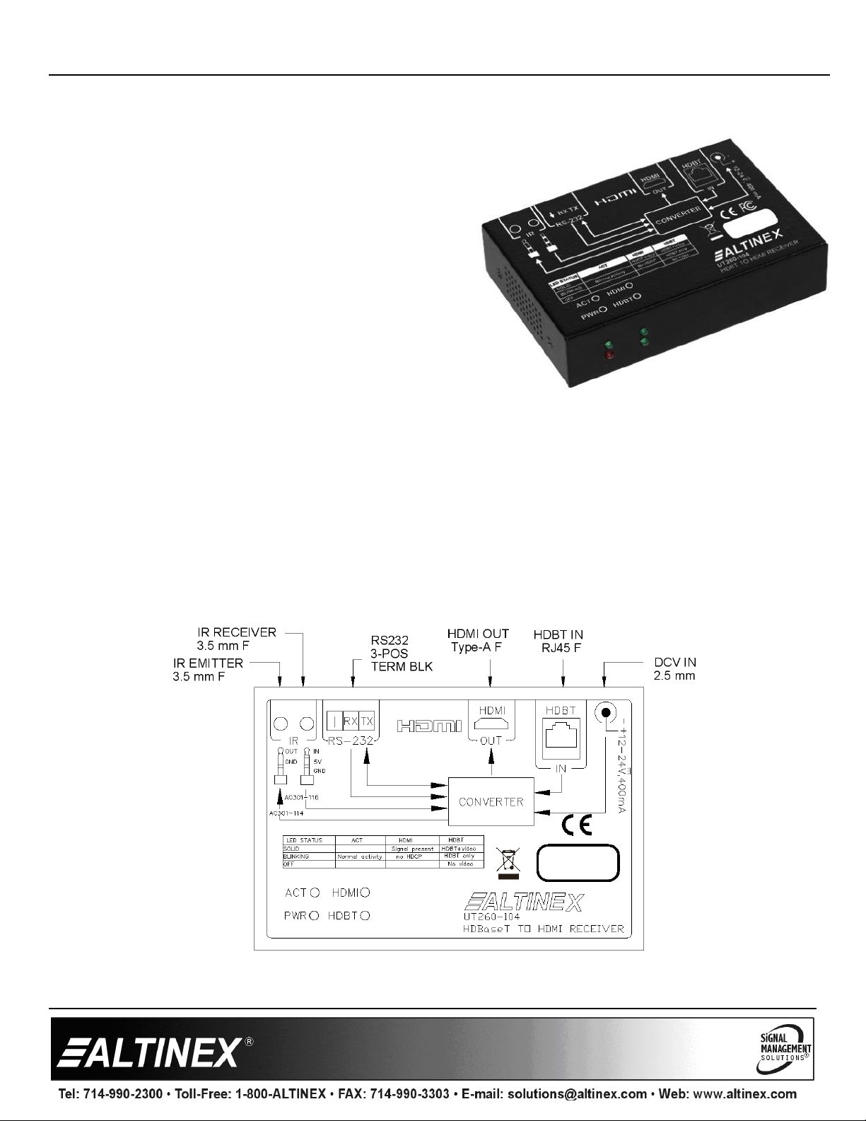
See the top label of the UT260-104 for control details, or refer to the complete online manual.
Step 1: The enclosure may be mounted to furniture or a wall
using the brackets included, or it can be attached to
the back of a display using 2-sided tape or hook and
latch tape.
Step 2: In order to use the brackets included, first remove the
two screws on each side of the unit. Use these screws to mount the brackets to the UT260-104.
Step 3. Mount the UT260-104 to the desired surface using the appropriate fasteners; not included.
Step 4. Connect the CAT-5e/6/7 input cable from the UT260-103 Transmitter.
Step 5. Connect the HDMI output to the UT260-104 directly to a TV or other display.
Step 6. Apply power to the unit using the power adapter provided, or the power can be supplied by the transmitted if POE is capable
on the network. Both the power adapter and POE may be connected at the same time.
Step 7. The UT260-104 is ready for use. If the transmitter is active, the video is present on the UT260-104 output.
Step 8. The UT260-104 can pass RS-232 and IR signals to and from the transmitter to control displays or sources. The label on the
top of the unit shows the connection details, or you can refer to the online manual. The IR emitter and receiver may be
purchased separately; emitter AC301-114 and receiver AC301-116.
3. Warranty and Return Policies
Please visit the Altinex website at www.altinex.com for details on warranty and return policies. In the case of a unit needing repair,
please complete a RMA (return material authorization) form located on the bottom left hand corner of the Altinex homepage. Once
completed, please email the form to [email protected].
UT260-104 User’s Guide
400-0680-001 2
4. Technical Specifications
Specifications are subject to change due to design improvements. Please see www.altinex.com for up to date information.
Features/Description
UT260-104
Input Connectors
HDMI Over HDBT
RJ-45 F (1)
Power
DC Jack 2.5 mm F (1)
Output Connectors
Digital Video + Audio
HDMI F, Type A (1)
Control
RS232/Input Select
Term. Blk. 3 position (1)
IR Output (to emitter)
3.5 mm F (1)
IR Input (from sensor)
3.5 mm F (1)
Compatibility
Digital Signal types
HDMI 1.4,3D, 4k 30Hz
DP 1.2
Signal resolution
Up to 4k x 2k 30 Hz
VGA
VESA up to 1920x1080
Accessories Included
Power Supply
24V/1A Power Adapter (1)
Mounting Brackets
Right Angle (2)
Terminal Blocks
3 position, 3.5 mm (1)
Optional Accessories
IR Emitter
AC301-114
IR Receiver
AC301-116
Table 1. UT260-104 General
Mechanical
UT260-104
Material
Steel
Color
Black
Height
0.98 in. (25 mm)
Width
2.95 in. (75 mm)
Length
4.37 in. (111 mm)
Weight
1.3 lb. (0.6 kg)
T° Operating
10°C-40°C
Humidity
60% RH non-condensing
MTBF (calc.)
38,000 hrs.
Table 2. UT260-104 Mechanical
Electrical
UT260-104
Video Input Signals
Digital Video + Audio on
HDBT
Altinex Standard
Output Signals
Digital Video + Audio
HDMI Standard
Power
+24VDC
500 mA, 24 W
Table 3. UT260-104 Electrical
HDMI, the HDMI Logo, and High Definition Multimedia
Interfaces are trademarks or registered trademarks of HDMI
Licensing LLC in the United States and other countries.
UT260-104 User’s Guide
400-0680-001 3
5. About Your UT260-104
Receive Audio/Video/Control up to 70m over one Cat 6/Cat
6A/Cat 7 cable
Support VGA with WUXGA resolution, HDMI 4k x 2K, DP 1.2
with 4K@30Hz
HDCP 1.4 compliant
IR and RS-232 pass through
Remote power from HDBT transmitter
Status LED on front
The UT260-104 HDBT Receiver is a high performance HDBT receiver
with HDMI output. In addition to video, the UT260-104 also allows both IR
and RS232 control signals from the transmitter to the receiver, or from
the receiver to the transmitter. The RS232 port is independently
configurable allowing different baud rates than the transmitter.
The TX+RX system supports manual or auto-switching modes, pass-through IR or RS232 controls, and custom audio selection.
Auto-switching automatically switches to the newest input. Manual control allows the switch to be controlled from user interface
momentary switches, RS232 protocols, or via the built-in web server. A special feature gives the user the ability to select between using
the embedded audio (HDMI/DP) or the external audio from the 3.5mm audio input port. The external audio is automatically selected
with the VGA input, but can also be used to override the HDMI or DP embedded audio.
A power supply is included with the UT260-104, or the UT260-104 receiver can be power by the UT260-103 transmitter when used with
a direct connection between the transmitter and receiver.
UT260-104 User’s Guide
400-0680-001 4
6. Application Diagrams
Diagram 1: Typical Setup
UT260-104 User’s Guide
400-0680-001 5
Diagram 2: Dimensions
UT260-104 User’s Guide
400-0680-001 6
Diagram 3: RS232 Pass-Through
UT260-104 User’s Guide
400-0680-001 7
7. Operation
Users connect their device (phone, laptop, etc.) to one of the
input connectors/cables above the table surface connected to
the transmitter. Their video input is automatically converted
and routed to the UT260-104 Receiver where the HDMI output
is displayed on the external display. Auto-switch is the default
configuration, but may also be disabled for use with contact
closures or a control system.
7.2 LED Indicators
The front panel has four LEDs representing the status of the
TX/RX system.
7.2.1 Power
The PWR LED is on and solid red when power is present.
7.2.2 Activity
The ACT LED is blinking during normal operation. This shows
activity between the transmitter and receiver.
7.2.3 HDMI
The HDMI LED is on and solid when a signal is present and
the display is connected. The display must be powered and not
in standby.
7.2.4 HDBT
The HDBT LED is blinking when connecting with the
transmitter and solid on during normal operation.
7.4 Pass-through Controls
The UT260-104 provides pass-through controls for IR and/or
RS232. Both can be used, but data cannot be simultaneous.
7.4.1 RS232 Pass-through
RS232 data can be passed from the transmitter to the receiver
and/or from the receiver to the transmitter. The RS232 ports on
each end can be configured with independent baud rates.
The default is 115200 baud. In order to change the baud rate,
use RS232, TCP, or web server options from the UT106-103
Transmitter.
7.4.2 IR Pass-through
Use the IR pass through option to send IR remote control
signals from the transmitter to the receiver or vice versa using
Altinex optional accessories:
AC301-114 IR Emitter
AC301-116 IR Receiver.
UT260-104 User’s Guide
400-0680-001 8
8. Troubleshooting Guide
We have carefully tested and have found no problems in the supplied UT260-104. However, we would like to offer suggestions for the
following:
Switcher
Symptom
Resolution
No Audio with VGA
Input
1. Make sure the VGA audio source is connected to the 3.5 mm audio input on the switcher.
2. Check the audio source to make sure the audio is playing and that the volume is turned up to a
reasonable level.
Poor Output Image
1. Verify the cable between the switcher output and the display is a genuine HDMI cable.
2. Troubleshoot with a lower gauge shorter distance HDMI cable.
RS232 Commands Not
Recognized
1. Make sure to include a carriage return at the end of the command or the switch will not
recognize the command.
2. Verify you are using the correct baud rate. Remember, the transmitter and receiver can be
configured with different baud rates.
3. The default baud rate is 115200 baud.
System Failure
1. Press and hold the input select button on the front of the unit until all input LEDs flash; about 12
seconds and then release. This performs a factory reset and should restore normal operation.
2. Please call the Altinex Customer Service Department at (714) 990-2300 to have the unit
repaired.

Popular TV Receiver manuals by other brands

AMX DTV-RX01-SD Installation instructions manual

AMX

AMX DTV-RX01-SD Installation instructions manual

Tevion Digital Freeview Receiver Quick setup guide

Tevion

Tevion Digital Freeview Receiver Quick setup guide

Conceptronic CTVDIGUSB2 Specifications

Conceptronic

Conceptronic CTVDIGUSB2 Specifications

DirecTV Wireless Cinema Connection Kit Get connected

DirecTV

DirecTV Wireless Cinema Connection Kit Get connected

PrimeDTV Technologies PHD-VRX owner's manual

PrimeDTV Technologies

PrimeDTV Technologies PHD-VRX owner's manual

Avermedia DVB-T STB5 user manual

Avermedia

Avermedia DVB-T STB5 user manual

Panasonic TU-DST52F Assembly guide

Panasonic

Panasonic TU-DST52F Assembly guide

TVonics MDR-240 user guide

TVonics

TVonics MDR-240 user guide

Technomate TM-5402 HD user manual

Technomate

Technomate TM-5402 HD user manual

Samsung SP43T7HLX Service manual

Samsung

Samsung SP43T7HLX Service manual

Teleview TAV900A user manual

Teleview

Teleview TAV900A user manual

Igloo DT840INZ user guide

Igloo

Igloo DT840INZ user guide

Manhattan Plaza HD T2 user guide

Manhattan

Manhattan Plaza HD T2 user guide

Strong SRT 82 user manual

Strong

Strong SRT 82 user manual

Nokia Mediamaster 310 S user guide

Nokia

Nokia Mediamaster 310 S user guide

Motorola at&t U-verse VIP2500 Series installation manual

Motorola

Motorola at&t U-verse VIP2500 Series installation manual

Strong SRT 5023X user manual

Strong

Strong SRT 5023X user manual

Genius TVGO DVB-T02Q manual

Genius

Genius TVGO DVB-T02Q manual

manuals.online logo
manuals.online logoBrands
  • About & Mission
  • Contact us
  • Privacy Policy
  • Terms and Conditions

Copyright 2025 Manuals.Online. All Rights Reserved.