ALTUS MLB 2204 H/W User manual

Motherboard
User Manual
MLB 2204 H/W
Sep. 2006 (Revision A)
P/N: 1230B0034801

Copyright Notice
All rights, including copyright, in the content of this manual are owned or controlled by IESC
and protected by the Taiwan and international copyright act.
No one may, transmit, adapt, assign, compile, rent, sale, change, copy, reproduce, distribute,
publish, display, broadcast, or use in any way the content of this manual, in whole or in part,
for any other purpose whatsoever without the prior written permission of IESC.
Trademarks
All product names or brands mentioned herein are the trademarks of IESC, its subsidiaries or
other respective owners in Taiwan, United States and other countries.
Disclaimer
This manual provides the information in relation to the set-up and installation of the product
herein. Nothing herein may be construed as granting any right or license relating to any
intellectual property rights of this manual or product. Unless otherwise provided in the
Purchase and Sale Agreement for this product, manufacturer and distributor of this product
will not be liable whatsoever relating to the distribution and/or use of this product. In addition,
manufacturer and distributor of this product hereby specifically disclaim any express or
implied warranties of merchantability, fitness for a particular purpose, or non-infringement of
third party rights in connection with this product.
Manufacturer of this product may have the right to change specifications and product
descriptions at any time without notice.

Contents
About This Manual ........................................................................................................................i
Conventions.................................................................................................................................i
Safety Symbols...........................................................................................................................ii
Safety Precautions..................................................................................................................... iii
Operation Safety .................................................................................................................... iii
Electrical Safety...................................................................................................................... iii
Battery Replacement Safety...................................................................................................iv
Laser Peripherals or Devices Safety .......................................................................................v
Intended Application Uses.......................................................................................................v
Site Selection ..........................................................................................................................v
Tools Required ........................................................................................................................v
Regulatory and Integration Information......................................................................................vi
Regulatory Compliance Identification Numbers......................................................................vi
Product Regulatory Compliance.............................................................................................vi
1Introduction ........................................................................................................................1-1
1.1 Audience Assumptions..................................................................................................1-1
1.2 Manual Organization.....................................................................................................1-1
1.3 Product Features...........................................................................................................1-2
1.4 Motherboard Layout......................................................................................................1-4
1.4.1 Connectors and Component Locations..................................................................1-4
1.4.2 Back Panel Connectors..........................................................................................1-6
2Hardware Operations.........................................................................................................2-1
2.1 Before You Start ............................................................................................................2-1
2.2 Screw Holes..................................................................................................................2-2
2.3 Battery...........................................................................................................................2-3
2.3.1 To remove the battery ............................................................................................2-3
2.3.2 To install the battery...............................................................................................2-4
2.4 Processor......................................................................................................................2-5
2.4.1 To remove the heat sink.........................................................................................2-6
2.4.2 To install the heat sink............................................................................................2-6
2.4.3 To remove the processor........................................................................................2-7
2.4.4 To install the processor ..........................................................................................2-8
2.5 System Memory ............................................................................................................2-9
2.5.1 DIMM Population..................................................................................................2-10
2.5.2 To remove a DIMM...............................................................................................2-12
2.5.3 To install a DIMM..................................................................................................2-12
2.6 System Configuration Switch ......................................................................................2-13

3Connectors and System Configuration Switch ...............................................................3-1
3.1 Power Connectors (J2, J1)............................................................................................3-1
3.1.1 Main Power Connector (J2) ...................................................................................3-1
3.1.2 Processor Power Connector (J1)...........................................................................3-2
3.2 IDE Connector (J57)......................................................................................................3-3
3.3 Floppy Connector (J35).................................................................................................3-5
3.4 Front Panel Connector (J49).........................................................................................3-6
3.5 Front Panel USB Connector (J53).................................................................................3-7
3.6 Onboard USB6/7 Connector (J48) ................................................................................3-8
3.7 Onboard USB4/5 Connector (J52) ................................................................................3-9
3.8 Fan Connectors (J27, J34, J30, J36, J40, J26, J301, J33, J25)..................................3-10
3.8.1 Fan Connectors (J27, J34, J30, J36, J40) ...........................................................3-10
3.8.2 System Fan1 Connector (J26) .............................................................................3-11
3.8.3 System Fan2 Connector (J301) ...........................................................................3-12
3.8.4 Processor Fan Connectors (J33, J25)..................................................................3-13
3.9 Chassis Intrusion Connector (J300)............................................................................3-14
3.10 Clear CMOS Connector (J42) .....................................................................................3-15
3.11 BMC Recovery Connector (J302)................................................................................3-16
3.12 BMC Writer Connector (J45).......................................................................................3-17
3.13 IPMB Connector (J44).................................................................................................3-18
3.14 D-sub VGA Port (J21)..................................................................................................3-19
3.15 Serial Port (J16) ..........................................................................................................3-20
3.16 Keyboard and Mouse Ports (J3)..................................................................................3-21
3.17 Rear Dual USB Port (J6).............................................................................................3-22
3.18 NIC Connectors (RJ45) (J13, J9)................................................................................3-23
3.19 System Configuration Switch Settings (SW1) .............................................................3-24
4BIOS Setup..........................................................................................................................4-1
4.1 BIOS Setup Utility..........................................................................................................4-1
4.2 Entering the BIOS Setup Utility.....................................................................................4-2
4.3 Keyboard Command Bar...............................................................................................4-3
4.4 BIOS Updates ...............................................................................................................4-5
4.4.1 BIOS Requirements...............................................................................................4-5
4.4.2 ROM Flash.............................................................................................................4-5
List of Figures
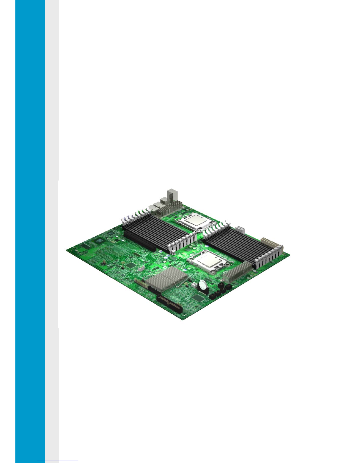
Figure 1-1 Motherboard Overview .....................................................................................1-2
Figure 1-2 Connectors and Component Locations ............................................................1-4
Figure 1-3 Back Panel Connectors....................................................................................1-6
Figure 2-1 Screws Placement............................................................................................2-2
Figure 2-2 Battery Location................................................................................................2-3
Figure 2-3 Pulling the Battery out of the Holder.................................................................2-3

Figure 2-4 Putting the Battery into the Holder....................................................................2-4
Figure 2-5 Processor Location...........................................................................................2-5
Figure 2-6 Pulling up the Heat Sink ...................................................................................2-6
Figure 2-7 Opening the Load Plate....................................................................................2-7
Figure 2-8 Lifting the Processor out of the Socket.............................................................2-7
Figure 2-9 Closing the Load Plate .....................................................................................2-7
Figure 2-10 Placing on the PnP Cap..................................................................................2-8
Figure 2-11 Aiming the Golden Corner at the Socket.........................................................2-8
Figure 2-12 System Memory Location...............................................................................2-9
Figure 2-13 DIMM Socket Location .................................................................................2-10
Figure 2-14 Lifting the DIMM out of the Socket................................................................2-12
Figure 2-15 Pressing the Retaining Clips.........................................................................2-12
Figure 2-16 Inserting the DIMM into the Socket...............................................................2-13
Figure 2-17 System Configuration Switch Location.........................................................2-13
Figure 3-1 Main Power Connector.....................................................................................3-1
Figure 3-2 Processor Power Connector.............................................................................3-2
Figure 3-3 IDE Connector..................................................................................................3-3
Figure 3-4 Floppy Connector.............................................................................................3-5
Figure 3-5 Front Panel Connector .....................................................................................3-6
Figure 3-6 Front Panel USB Connector.............................................................................3-7
Figure 3-7 Onboard USB6/7 Connector.............................................................................3-8
Figure 3-8 Onboard USB4/5 Connector.............................................................................3-9
Figure 3-9 Fan Connectors..............................................................................................3-10
Figure 3-10 System Fan1 Connector...............................................................................3-11
Figure 3-11 System Fan2 Connector...............................................................................3-12
Figure 3-12 Processor Fan Connectors...........................................................................3-13
Figure 3-13 Chassis Intrusion Connector.........................................................................3-14
Figure 3-14 Clear CMOS Connector................................................................................3-15
Figure 3-15 BMC Recovery Connector............................................................................3-16
Figure 3-16 BMC Writer Connector..................................................................................3-17
Figure 3-17 IPMB Connector...........................................................................................3-18
Figure 3-18 D-sub VGA Port............................................................................................3-19
Figure 3-19 Serial Port.....................................................................................................3-20
Figure 3-20 PS/2 Keyboard and Mouse Ports .................................................................3-21
Figure 3-21 Rear Dual USB Port .....................................................................................3-22
Figure 3-22 NIC Connectors (RJ45) ................................................................................3-23
Figure 3-23 System Configuration Switch........................................................................3-24
List of Tables
Table 1-1 Introduction of the Manual..................................................................................1-1
Table 1-2 Product Features................................................................................................1-2
Table 2-1 DIMM Installation Option 1...............................................................................2-11

Table 2-2 DIMM Installation Option 2...............................................................................2-11
Table 3-1 Main Power Connector Pin Definition.................................................................3-2
Table 3-2 Processor Power Connector Pin Definition ........................................................3-3
Table 3-3 IDE Connector Pin Definition..............................................................................3-4
Table 3-4 Floppy Connector Pin Definition.........................................................................3-5
Table 3-5 Front Panel Connector Pin Definition.................................................................3-6
Table 3-6 Front Panel USB Connector Pin Definition.........................................................3-7
Table 3-7 Onboard USB6/7 Connector Pin Definition ........................................................3-8
Table 3-8 Onboard USB4/5 Connector Pin Definition ........................................................3-9
Table 3-9 Fan Connector Pin Definition ...........................................................................3-10
Table 3-10 System Fan1 Connector Pin Definition ..........................................................3-11
Table 3-11 System Fan2 Connector Pin Definition...........................................................3-12
Table 3-12 Processor Fan Connector Pin Definition ........................................................3-13
Table 3-13 Chassis Intrusion Connector Pin Definition....................................................3-14
Table 3-14 Clear CMOS Connector Pin Definition ...........................................................3-15
Table 3-15 BMC Recovery Connector Pin Definition .......................................................3-16
Table 3-16 BMC Writer Connector Pin Definition.............................................................3-17
Table 3-17 IPMB Connector Pin Definition.......................................................................3-18
Table 3-18 D-sub VGA Port Pin Definition........................................................................3-19
Table 3-19 Serial Port Pin Definition ................................................................................3-20
Table 3-20 Keyboard Port Pin Definition..........................................................................3-21
Table 3-21 Mouse Port Pin Definition...............................................................................3-21
Table 3-22 Rear Dual USB Port Pin Definition.................................................................3-22
Table 3-23 NIC Connector (RJ45) Pin Definition..............................................................3-23
Table 3-24 System Configuration Switch Function...........................................................3-24
Table 4-1 BIOS Setup Utility Screen Description...............................................................4-2
Table 4-2 Keyboard Command Bar Description.................................................................4-3
Table 4-3 BIOS Requirements Description ........................................................................4-5

Conventions
Safety Symbols
Safety Precautions
Regulatory and Integration Information
About This Manual

About This Manual
1230B0034801 i
About This Manual
Conventions
To make sure that you perform certain tasks properly, take note of the following symbols used
throughout this manual.
Warning: Information to prevent injury to yourself when trying to complete a
task.
Caution: Information to prevent damage to the components when trying to
complete a task.
Important: Information that you must follow to complete a task.
Note: Tips and information to aid in completing a task.

About This Manual
1230B0034801 ii
Safety Symbols
Before troubleshooting, you must be familiar with the safety information listed below. In order
to avoid any potential hazards, the following symbols may be placed on some components of
the server.
The shape and the color of symbols shown below are mainly for your reference. Please take
the actual shipment as standard.
Indicates the potential hazard of energy circuits or electric shock. To reduce
the risk of injury from electric hazards, do not open this enclosure.
Warning: Any surface or area of the equipment marked with this symbol
indicates the presence of electric shock hazards. The enclosed area contains
no operator serviceable parts.
Indicates the potential hazard of electric shock. The enclosed area contains no
user of field serviceable parts. Do not open for any reason.
Warning: To reduce the risk of injury from electric shock hazards, do not open this
enclosure.
Indicates the presence of a hot surface or hot component.
Warning: To reduce the risk of injury from a hot component, allow the surface
to cool before touching it.
Any RJ45 receptacle marked with this symbol indicates a network interface
connection.
Warning: To reduce the risk of electric shock, fire, or damage to the
equipment, do not plug telephone or telecommunications connectors into this
receptacle.
This symbol, on power supplies or systems, indicates that the equipment is
supplied by multiple sources of power.
Warning: To reduce the risk of injury from electric shock, remove all power
cords to completely disconnect power from the system.
Weight in kg
Weight in lb
This symbol indicates that the component exceeds the recommended weight
for one individual to handle safely.
Warning: To reduce the risk of personal injury or damage to the equipment,
observe local occupational health and safety requirements and guidelines for
manual material handling.

About This Manual
1230B0034801 iii
Safety Precautions
Observe the following safety precautions when you are connecting or disconnecting any
device.
• Regarding the standards of workstation regulations, do not place the server in the visual
field of the user, because of the glossy front of the case.
• The product is non-consumer product and for profession technical person used only.
Operation Safety
• Any operation on this server must be conducted by certified or experienced engineers.
• Before operating your server, carefully read all the manuals included with the server
package.
• Before using the server, make sure that all cables are correctly connected and power
cables are not damaged. If any damage is detected, contact your dealer as soon as
possible.
• To avoid short circuits, keep paper clips, screws, and staples away from connectors, slots,
sockets and circuitry.
• Before opening the chassis panels, make sure all power cables are unplugged.
• Avoid dust, humidity, and extreme temperatures, place the server on a stable surface.
• If the power supply is broken, do not try to fix it by yourself. Contact an authorized dealer.
• It is recommended that you wear gloves when assembling or disassembling the server to
protect from cuts and scrapes.
• When the server is powered on, heat sinks and the surfaces of certain IC devices may be
hot. Do not touch them. Check whether the fans are functioning properly.
Electrical Safety
• Before installing or removing signal cables, ensure that the power cables for the system
unit and all attached devices are unplugged.
• To prevent electric shock hazard, disconnect the power cable from the electrical outlet
before relocating the system.
• When adding or removing any additional devices to or from the system, ensure that the
power cables for those devices are unplugged before the signal cables are connected. If
possible, disconnect all power cables from the existing system before you add a device.
• Use one hand, when possible, to connect or disconnect signal cables to prevent a possible

About This Manual
1230B0034801 iv
shock from touching two surfaces with different electrical potentials.
• This product is equipped with a three-wire power cable and plug for user safety. Use the
power cable with a properly grounded electrical outlet to avoid electric shock.
Motherboards, adapters, and disk drives are sensitive to static electricity discharge. These
devices are wrapped in antistatic bags to prevent this damage. Take the following
precautions:
• If you have an antistatic wrist strap available, use it while handling the device.
• Do not remove the device from the antistatic bag until you are ready to install the device in
the system unit.
• With the device still in its antistatic bag, touch it to a metal frame of the system.
• Grasp cards and boards by the edges. Hold drives by the frame. Avoid touching the solder
joints or pins.
• If you need to lay the device down while it is out of the antistatic bag. Lay it on the antistatic
bag. Before picking it up again, touch the antistatic bag and the metal frame of the system
unit at the same time.
• Handle the devices carefully to prevent permanent damage.
Battery Replacement Safety
This server is provided with an internal Lithium battery or battery pack. There is a danger of
explosion and risk of personal injury if the battery is incorrectly replaced or mistreated.
For more information about battery replacement or proper disposal, contact an authorized
reseller or your authorized service provider.
This server contains an internal Lithium Manganese Dioxide, or a Vanadium Pentoxide, or an
alkaline battery pack. There is risk of fire and burns if the battery pack is not handled properly.
To reduce the risk of personal injury:
• Do not attempt to recharge the battery.
• Do not expose to temperatures higher than 70°C.
• Do not disassemble, crush, puncture, shorten external contacts, or dispose in fire or water.
• Replace only with the spare parts designated for this product.

About This Manual
1230B0034801 v
Batteries should not be littered along with the general household waste. Please use the public
collection system or return them to the supplier.
Laser Peripherals or Devices Safety
To avoid risk of radiation exposure and/or personal injury:
• Do not open the enclosure of any laser peripheral or device.
• Laser peripherals or devices are not user serviceable.
• Return to manufacturer for servicing.
IntendedApplication Uses
This product was evaluated as Information Technology Equipment (ITE), which may be
installed in offices, schools, computer rooms, and similar commercial type locations. The
suitability of this product for other product categories and environments (such as medical,
industrial, residential, alarm systems, and test equipment), other than an ITE application, may
require further evaluation.
Site Selection
The system is designed to operate in a typical office environment. Choose a site that is:
• Clean, dry, and free of airborne particles (other than normal room dust).
• Well-ventilated and away from sources of heat including direct sunlight and radiators.
• Away from sources of vibration or physical shock.
• Isolated from strong electromagnetic fields produced by electrical devices.
• In regions that are susceptible to electrical storms, we recommend you plug your system
into a surge suppresser and disconnect telecommunication lines to your modem during an
electrical storm.
• Provided with a properly grounded wall outlet.
• Provided with sufficient space to access the power supply cord(s), because they serve as
the product's main power.
Tools Required
A cross screwdriver or a flat screwdriver is needed to install or remove the components in the
server.

About This Manual
1230B0034801 vi
Regulatory and Integration Information
Regulatory Compliance Identification Numbers
For the purpose of regulatory compliance certifications and identification, this motherboard is
assigned a serial number. This server serial number can be found on the product label, along
with the required approval markings and information. When requesting certification
information for this product, always refer to this serial number. This serial number should not
be confused with the marketing name or model number.
Product Regulatory Compliance
Product Safety Compliance
The motherboard complies with the following safety requirements:
IEC 60950-1 Safety of Information Technology Equipment
EN 60950-1 Safety of Information Technology Equipment Including Electrical Business
Equipment, European Committee for Electrotechnical Standardization
(CENELEC)
UL 60950-1 Safety of Information Technology Equipment
UL 94 Tests for Flammability of Plastic Materials for Parts in Devices &
Appliances
GB4943 Safety of Information Technology Equipment
Worldwide Safety approvals can be supplied according to the requirements from Marketing or
Customer.
Product EMC Compliance
This product has been tested and verified to comply with the following electromagnetic
compatibility (EMC) regulations.
Communications Commission Notice
Part 15 of the Federal Communications Commission (FCC) Rules and Regulations has
established Radio Frequency (RF) emission limits to provide an interference-free radio
frequency spectrum. Many electronic devices, including computers, generate RF energy
incidental to their intended function and are, therefore, covered by these rules. These rules
place computers and related peripheral devices into two classes, A and B, depending upon
their intended installation. Class A devices are those that may reasonably be expected to be
installed in a business or commercial environment. Class B devices are those that may

About This Manual
1230B0034801 vii
reasonably be expected to be installed in a residential environment (for example, personal
computers). The FCC requires devices in both classes to bear a label indicating the
interference potential of the device as well as additional operating instructions for the user.
The rating label on the device shows which class (A or B) the equipment falls into. Class A
devices do not have an FCC logo or FCC ID on the label. Class B devices have an FCC logo
or FCC ID on the label. Once the class of the device is determined, refer to the following
corresponding statement.
Class A Equipment
This equipment has been tested and found to comply with the limits for a Class A digital
device, pursuant to Part 15 of the FCC Rules. These limits are designed to provide
reasonable protection against harmful interference when the equipment is operated in a
commercial environment. This equipment generates, uses, and can radiate radio frequency
energy and, if not installed and used in accordance with the instructions, may cause harmful
interference to radio communications. Operation of this equipment in a residential area is
likely to cause harmful interference, in which case the user will be required to correct the
interference at personal expense.
Declaration of Conformity for Products Marked with the FCC Logo—United States Only
This device complies with Part 15 of the FCC Rules Operation and is subject to the following
two conditions: (1) this device may not cause harmful interference, and (2) this device must
accept any interference received, including interference that may cause undesired operation.
For questions regarding your product, please contact the supplier.
To identify this product, refer to the Part, Series, or Model number found on the product.
European Union Notice
Products with the CE Marking comply with both the EMC Directive (89/336/EEC) and the
Low-Voltage Directive (73/23/EEC) issued by the Commission of the European Community.
Compliance with these directives implies conformity to the following European Norms (in
brackets are the equivalent international standards):
EN55022 (CISPR 22) Electromagnetic Interference
EN55024
(IEC61000-4-2,3,4,5,6,8,11) Electromagnetic Immunity
EN61000-3-2 (IEC61000-3-2) Power Line Harmonics
EN61000-3-3 (IEC61000-3-3) Power Line Flicker
EN60950 (IEC950) Product Safety

About This Manual
1230B0034801 viii
Canadian Notice (Avis Canadien)
Class A Equipment
Japanese Notice
Taiwanese Notice

AudienceAssumptions
Manual Organization
Product Features
Motherboard Layout
Chapter 1
Introduction

Introduction
1230B0034801 1-1
1 Introduction
1.1 AudienceAssumptions
This manual assumes that you are a service technician or network administrator familiar with
computer hardware, data storage and network administration terminology and tasks.
1.2 Manual Organization
This manual introduces the motherboard with the hardware information, how to replace the
hardware. This manual is generally organized as follows:
Table 1-1 Introduction of the Manual
Introduction The general introduction to the board.
Hardware Operations The operation of the components on the motherboard, such as
battery, processor, system memory, and so forth.
Connectors and
System Configuration
Switch
Some necessary information of the connectors and switch on the
motherboard.
BIOS Setup Information about BIOS setup.

Introduction
1230B0034801 1-2
1.3 Product Features
This chapter provides the detailed features for processor, memory, onboard LAN, D-sub VGA,
I/O and PCI with pictures for your reference.
Figure 1-1 Motherboard Overview
This motherboard dimension is designed for 12” x 13”. The motherboard is configured to use
nVIDIA MCP55 PRO chipset. It supports dual AMD®Opteron™ 2200 series processors with
1.0GHz Hyper Transport Bus to accelerate even the most complicated server tasks. The
following highlights are the main features of the motherboard. For additional information, refer
to this user manual.
Table 1-2 Product Features
Processor Dual AMD®Opteron™ 2200 series processors with 1.0GHz
Hyper Transport Bus
Hyper-Transport™ Technology Support
Located on two LGA 1207-pin sockets F
Chipset nVIDIA MCP55 PRO
Memory Sixteen 240-pin DIMM vertical sockets
Supports up to 64GB of registered DDR2 667MHz
Support ECC
Onboard LAN Two Gigabit Ethernet RJ45 ports
Network controllers embedded in nVIDIA MCP55 PRO
10/100/1000Mbps

Introduction
1230B0034801 1-3
Supports jumbo frame, RSS, and check sum offload
Onboard VGA ATI RN 50 (ES1000)
32MB display RAM
PCI 32bit/33MHz interface
Integrated Super I/O Winbond83627HG controller
Supports one fast UART 16550 serial port, one PS/2 keyboard
port, and one PS/2 mouse port
Expansion Slots Expansion Slots (1U Chassis)
One PCI-E x16 expansion slot with x16 speed
Expansion Slots (5U Chassis)
One PCI-E x16 expansion slot with x16 speed
One PCI-E x8 expansion slot with x4 speed
One PCI-E x8 expansion slot with x8 speed
One audio expansion slot

Introduction
1230B0034801 1-4
1.4 Motherboard Layout
The layout of the motherboard is shown below. Each connector and major component is
identified by the number.
1.4.1 Connectors and Component Locations
Figure 1-2 Connectors and Component Locations
• The words printed on the real motherboard to mark the processors are “CPU0”
and “CPU1”. Here just for consistency, the processors are marked with
“PROCESSOR0” and “PROCESSOR1” in the picture above.
• All the connectors for 1U and 5U are shown in the picture above. In the table
below, the specific connectors for 5U are marked out.
Table of contents
Other ALTUS Motherboard manuals
Popular Motherboard manuals by other brands

Supermicro
Supermicro X7DWT user manual

Portwell
Portwell ROBO-8113VG2AR user guide

DEC
DEC AlphaPC 164LX Technical reference manual

Telit Wireless Solutions
Telit Wireless Solutions xE910 user guide

Nvidia
Nvidia zotac nforce 790i-supreme Quick reference guide

Analog Devices
Analog Devices AD9136/AD9135-EBZ quick start guide