Alware Lensman-Pro 3 Axis User manual

Lensman-Pro 3 Axis
DSLR Brushless Gimbal
(For Handheld/ DJIS 00/ 1000)
Instruction Manual
Updated Date: 22 Sept 2014
1

Table of Contents
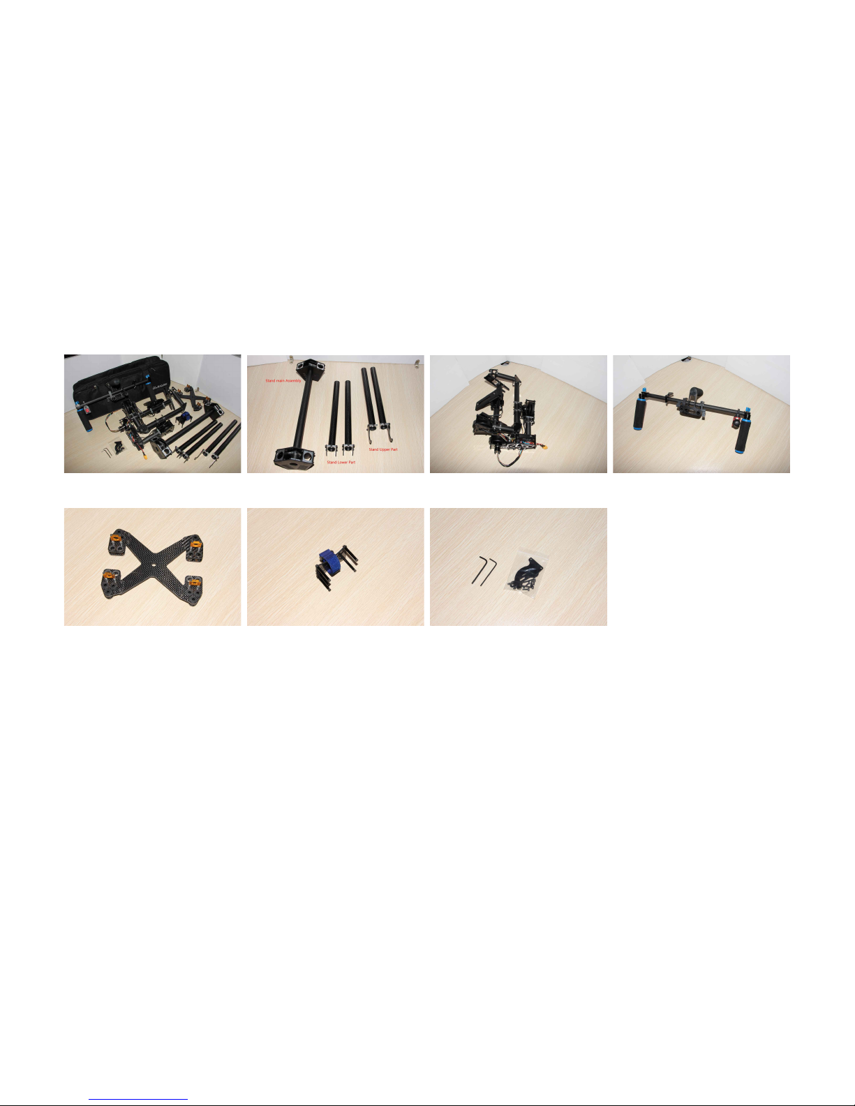
Check list.....................................................................................................................................................................3
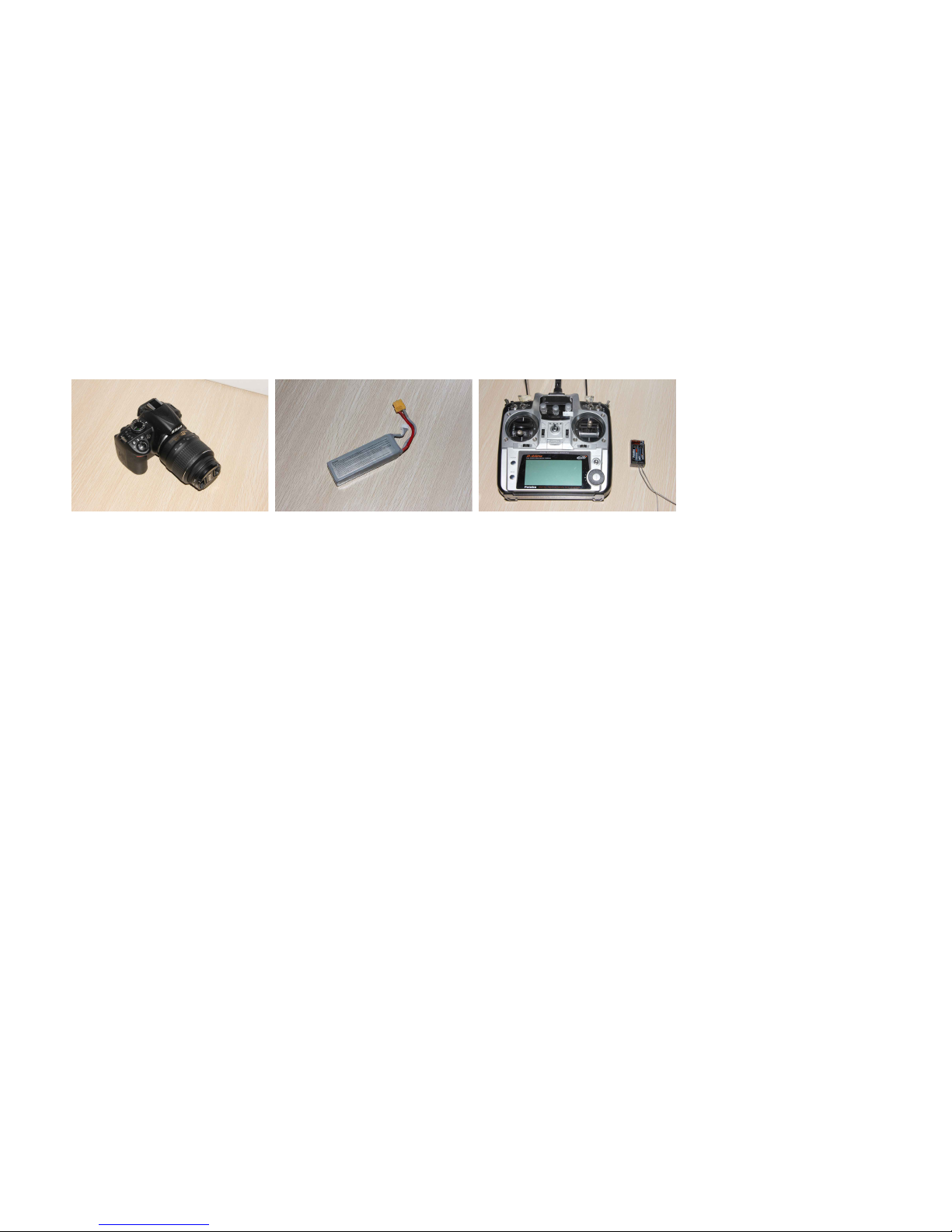
Equipment Required To Operate.................................................................................................................................4
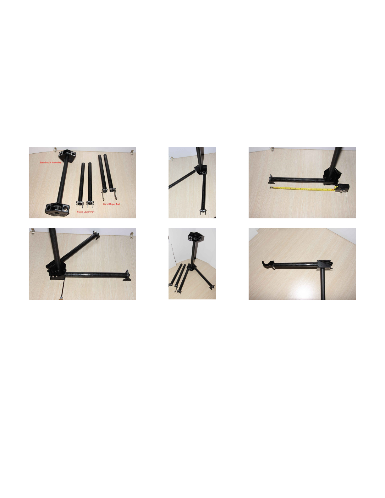
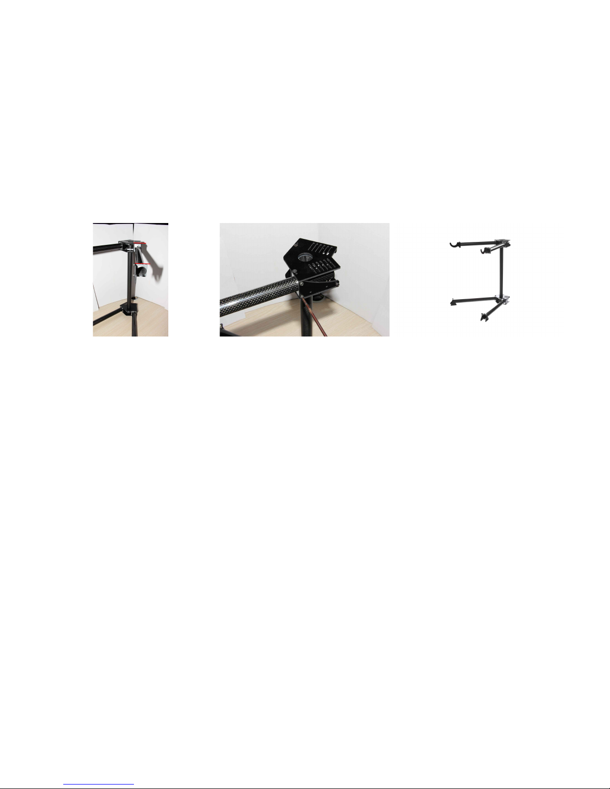
STEP 1: Stand Assem ly.............................................................................................................................................5
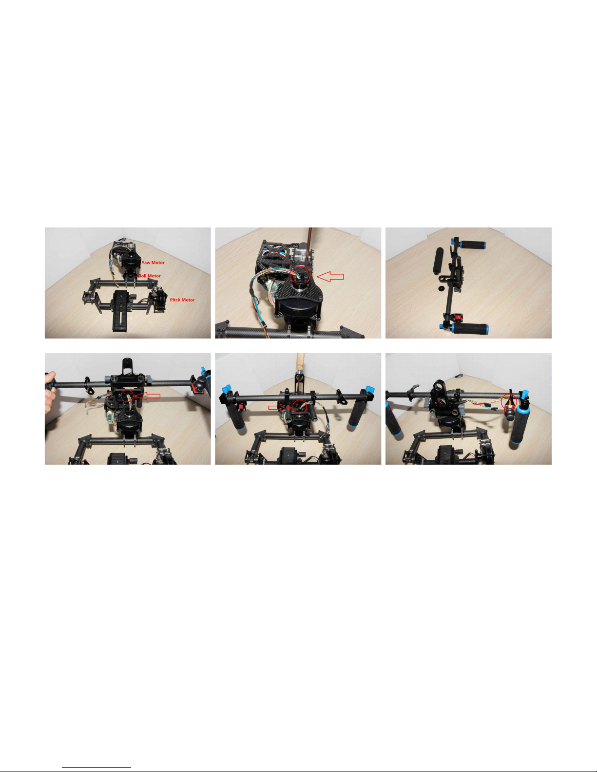
STEP 2: Gim al Assem ly..........................................................................................................................................7
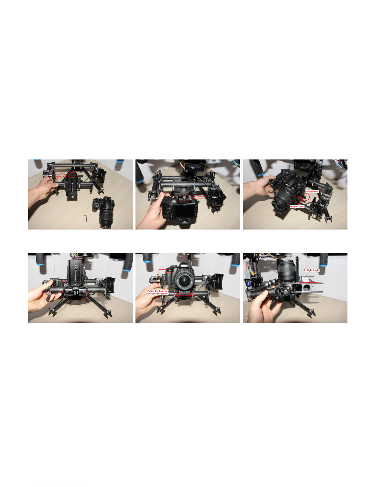
STEP 3: Gim al Balancing – Pitch Axis.....................................................................................................................9
STEP 5: Gim al Balancing – Roll Axis.....................................................................................................................12
STEP 6: Gim al Balancing – Yaw Axis....................................................................................................................14
STEP 7: Power On and Controling............................................................................................................................16
STEP 8: Converting to Aerial Mode..........................................................................................................................17
STEP 9: Gim al Tuning Software.............................................................................................................................19
STEP 10: Firmware Upgrade.....................................................................................................................................21
End of Manual...........................................................................................................................................................23
2

Check list
All the package should be packed and contain all the items as shown below. Please contact the vendor you purchased from if anything is missing at
once.
Alware Accessory Carry Bag and
with the Parts
Stand Assembly Parts Main Body Assembly Handle nit
X-Mounting nit Battery Holder Hexagon Screw Driver (1.5mm and
2.0mm) and Spare Parts
3

Equipment Required To Operate
DSLR Camera 3S 11.1V 2200mAh (or above) Lipo
with XT-60 Connector
3 Channel Radio and Receiver
(Optional)
4

STEP 1: Stand Assembl
Insert the Stand Lower Parts Around 265mm
Secure the Stand Lower Parts by Tighten one
screw.
Insert the Stand Upper Parts
5

Adjust the position to be Para e . Secure the Stand Upper Part by Tighten one
Screw
Comp ete Assemb y of Stand Unit
6

STEP 2: Gimbal Assembl
Put the Main Body Assemb y as shown. Take off four Mounting Screws. Re ease the Upper Hand e of the Hand e Unit.
Insert the Main Cab e through the ho e. Secure the Hand e Unit to the Yaw Motor
with 4pcs Screws.
P ug the 5-wires Cab e to the Joystick.
7

Insta back the Upper Hand e. Put the Gimba on the Stand. Re ease four Screws from the Battery Ho der.
Insert that four Screws to the frame as
Shown.
Secure the Battery Ho der. Tighten your Battery to the Gimba before
move on to next step.
8

STEP 3: Gimbal Balancing – Pitch Axis
Balancing the Center of Gravity (CG) for a Brushless Gim al is extremely import. The more accurate the CG, the etter the gim al
performance will e. Balancing require experience and time, so e patient.
Before start Ba ancing the Gimba , make sure
your Camera has a accessory(e.g. Battery, SD
Card etc.) insta ed.
Secure your Camera comp ete y. Adjust the Camera to the midd e position and
ock it by the Position Lock.
Loosen two Screws (Ho d the Camera at the
same time)
Adjust the Camera to be c oser to the Gimba
Frame.
Keep in 90 Degree ang e before tighten the
Screws.
9

Tighten these Screws. Ho ding the Side Fame of the Gimba . Ti t the Camera in about 45 degrees. Camera
shou d remain steady there when you re ease
you hand when the CG is correct.
Loosen tota 8pcs Screws as to adjust the Up-
Down position of the camera if the CG is not
correct. (Ho d the Camera at the same time)
Adjust the Camera (Up/ Down) and tighten
8pcs Screws again.
Test the CG again in about 45 degrees. Repeat
the previous Steps if the CG is sti not
accurate. (Be Patient Here)
10

Tighten a 8pcs Screws when the CG is we
tuned.
Make sure the Camera P ate is a ways set to
be 90 degree (right ang e).
Test the CG again with more ang es. Camera
shou d remain steady in any ang e if the CG is
set correct y.
11

STEP 5: Gimbal Balancing – Roll Axis
Loosen these 2 Screws. (Ho d the Camera at
the same time)
Adjust the Ro Assemb y to Left/ Right as to
ba ance the CG.
Set it to be Para e before tighten the Screws.
Tighten these 2 Screws. Test if the Ro Axis is ba anced we . The Ro
Assemb y(with Camera) shou d a ways remain
steady in any Ang e if it has correct CG.
Test on about 45 degree. Camera shou d
remain steady if the CG is correct. Repeat the
previous steps to get the correct CG. (Be
Patient Here)
12

Test again in another position. Test again in another position. Test again in another position.
13

STEP 6: Gimbal Balancing – Yaw Axis
Rotate the Gimba Main Assemb y as to
Para e to the Hand e Bar.
Ti t the Hand e Unit to test if the Yaw Axis has
correct CG. The Camera shou d remain steady
if the CG is correct.
Adjust the Gimba in this direction if the CG is
not correct.
Loosen these 2 Screws before the
adjustment.
Test again in the oppose position. Repeat the
previous steps if the CG is not correct. (Be
Patient Here)
14

Set the Gimba Main Assemb y to be around
45 degree. Ti t the Hand e, the Camera
shou d remain steady if the CG is correct.
If not, oosen these 2 screws and do the
adjustment.
Adjust the CG by given a sma rotation of the
assemb y.
Tighten the Screws and test again. The Camera shou d remain steady if it got the
correct CG position. If not, repeat the
previous steps and for the adjustment again.
(Be Patient Here)
15

STEP 7: Power On and Controling
P ace the Gimba on the Stand and set to this
recommended position.
Connect the 3S 11.1V Battery to the Gimba
and wait around 3-5 seconds for the
initia ization.
Gimba is now contro ab e by the Joystick.
Operation Modes cou d be refer to:
Operation Video
Beside then the Joystick, you are ab e to
contro the Gimba with the Mobi e App too.
Prepare a 3 Channe s Raido and Receiver if
you want to have wire ess contro of the
gimba .
Connect the Wire ess Contro Cab e to the
Receiver.
3-wires Cab e: Contro Lock and Fo ow Mode
(Connet to any 2-way or 3-way switch channe )
B ue wire: Contro Yaw movement
Green wire: Contro Pitch movement
16

STEP 8: Converting to Aeria Mode
Before Converting to Aeria Mode, main sure your Gimba is entered in the Mode 4. When the Gimba is powered on, Press 4 times of the
Joystick as to enter to Mode 4. Now you can turn off the Gimba and convert it to an Aeria Mode easi y.
Push the Joystick Re ease the Upper Hand e. Re ease the 4 Mounting Screws. Take off the Hand e Unit.
Prepare the X-Mounting Unit Insert the Main Cab e through the ho e of X-
mounting.
Secure the X-Mounting with 4 Screws. (App y
Litt e Thread-Locker to the Screws.)
17

Connect the RC Contro Cab e to three
channe s of your Receiver.
3-wires Cab e: Contro Lock and Fo ow Mode
(Connet to any 2-way or 3-way switch channe )
B ue wire: Contro Yaw movement
Green wire: Contro Pitch movement
Comp ete assemb y in Aeria Mode. Insta ing on Cyc one X8/ DJI S800/ 1000
mu ticopters.
18

STEP 9: Gimbal Tuning Software
Specification for the 32 its SimpleBGC Camera Sta ilizer System with [Lensman-Pro Gim al]:
Board: version 3.0
Firmware: v2.42 7 (Can e upgraded via the GUI software easily!)
Tuning Software: SimpleBGC GUI v2.42 7
Input Voltage: 11.1V 3S Lipo with XT-60 Connector (for the Default Setting)
Default PID and Power Setting suitable for: DSLR Camera with Lens 0.8-1.4kg
(Remarks: For other camera out of this range will need to have different PID setting.)
How to connect to the computer?
Step 1.
Download the newest software for 32 its Controller e.g. “ SimpleBGC_GUI_2_42 7.zip ” at the official we site
http://www. asecamelectronics.com/downloads/32 it/
Step 2.
Connect the Gim al Control Board to the computer. No attery is needed at the moment. Wait for around 1-2 mins for the driver to e
installed automatically. When the driver has een installed successfully, you will get a notice from your computer.
If your computer fail to install the Driver automatically, download the driver here and install it manually:
http://www.sila s.com/products/mcu/pages/us touart ridgevcpdrivers.aspx
19

Step 3.
Run the GUI Software (2_42 7): SimpleBGC_GUI_2_42 7 → SimpleBGC_GUI(.exe)
Step 1. Run the GUI.exe Software Step 2. Se ect the correct COM, then c ick
Connect
Step 3. If the Connection is successfu , you
wi see the current firmware. Before start
tuning the gimba , se ect the specific Profi e
(mean the Mode) and c ick “Write” button.
As to save your new parameters, a ways c ick the “WRTE” button.
Remarks: As to understand the working principle of PID/ other specific tuning, you can refer to the offical manual of the Gimbal ontroller:
Simp eBGC_32bit_manua _2_42_eng.pdf
20
Table of contents
Other Alware Camera Accessories manuals