Amate Audio Xamp3K User manual

User’s manual
Manual de usuario
Xamp3K
Power amplifier for bi-amplified Xcellence Speaker Systems
Amplificador de potencia para Sistemas de Altavoces Xcellence bi-amplificados
May 2016

Xamp3K May 2016
2 Amate Audio
ENGLISH
Safety Instructions
1. All safety instructions must be read before using this device.
2. The exclamation mark in the triangle indicates internal components which if
replaced can affect safety.
3. The lightning symbol within the triangle indicates the presence of dangerous
uninsulated voltages.
4. This device must not be exposed to rain or humidity.
5. Only clean the device with a dry cloth.
6. Do not situate the equipment where its ventilation system might be interfered with.
7. Do not install the device near heat sources such as radiators, heaters or other
heat-emitting elements.
8. The equipment must be repaired by qualified technical service personnel when:
A. The mains supply cable is damaged, or
B. Any object or liquid has damaged the device; or
C. The equipment does not function normally or correctly; or
D. The equipment has been exposed to the rain; or
E. The chassis is damaged
9. Disconnect the device in the case of electric storms or during long periods of
disuse.
10. The equipment shall not be exposed to dripping or splashing and no objects filled
with liquids, such as vases, shall be placed on the device.
11. Only use manufacturer recommended accessories.

Xamp3K May 2016
3 Amate Audio
1 INTRODUCTION
Amate Audio would like to thank you for the trust placed in our Xamp3K. We have
incorporated the highest technology into this product with the conviction that will give
you an optimum performance and operation, however adverse the working
conditions to which you may submit it. In order to achieve the best performance
and correct operation, it is important that you read the instruction manual carefully
before making any connections. In addition, we recommend that you read the
Warranty Certificate enclosed with this Equipment in case you may observe any
anomaly prior to or immediately after start up, and how to proceed on each case.
The Xamp3K is an amplifier with a dedicated design to drive two-way bi-amplified
speaker systems of the Xcellence series.
A 2400 W@4 Ohms Class H channel for low frequency plus a 600 W@4 Ohms
channel for high frequency offer flexible, reliable and powerful option for most
loudspeakers combinations.
Together with our DSP608 loudspeaker management controller, they are the perfect
match to drive your loudspeakers in applications where active solutions cannot be
deployed.
Shipped contents:
- Xamp3K unit
- AC power cord
- User Manual

Xamp3K May 2016
4 Amate Audio
2 MAIN FEATURES
The Xamp3K amplifier is modular in design. The rigid metal chassis provides easy
access to the electronic circuits. Fully independent safety circuits protect the
amplifier in the event of a short circuit of the loudspeaker output, abnormal increases
in temperature and/or excessive amplifier consumption.
The Xamp3K amplifier offers high dynamic performance with moderate average
energy consumption, as well as good damping factor, which results in clean
response to transients and high quality playback.
The power modules are integrated in a tunnel-shaped own developed heat sink,
which combines high dissipation power with an excellent thermal inertia, thanks to
the high extraction effectiveness of the incorporated fans.
Other features include:
- Separate input XLR, electronically balanced for each way (Low & High)
- Volume control, limiter and indicators VU for each way (channel)
- Output for both ways via one single 4-pole Speakon, with an additional LINK
Speakon (PARALLEL). Independent binding posts may be also used.

Xamp3K May 2016
5 Amate Audio
3 MAIN CONTROLS AND CONNECTIONS
3.1 The front panel
Fig. 1. Front panel view
A) Power Switch – On-Off switch with Led
B) Volume Controls – Potentiometers to independently control the output level for
each way.
C) Cooling outs – Forced air output for temperature regulation.
D) VU-Meters – Independent output signal indicators, with Leds for different relative
levels: -36dB, -24dB & -12dB.
E) Limiter – Led indicating the operation start of the anti-clipping or limiter systems.
F) Protection – Led indicating the operation of any of the protection system of one
or both channels. At power up normally it will turn ON momentarily. If it does not
turn OFF, indicates a problem of malfunction of the amplifier.
G) Panel screws – Detach (no tools needed) to access the internal panel
3.2 The internal front panel
Detach the front panel using the two screws (G) to access this panel.
Fig. 2. Internal front panel
H) Limiter adjust – Easy adjustment for the limiter threshold of each output. For
more information see Section “Limiter Adjustment”.

Xamp3K May 2016
6 Amate Audio
3.3 The rear panel
Fig. 3. Rear panel view
A) IEC power connector /Breaker – Input power supply 230VAC with overcurrent
protection of 10 A RMS.
B) XLR Input (LOW) – Electronically balanced for channel of 2400W @ 4Ohm.
C) XLR Input (HIGH) – Electronically balanced for channel of 600W @ 4Ohm.
D) XLR Link (Out LOW) – Signal link of the LOW channel (for another amplifier).
E) XLR Link (Out HIGH) – Signal link of the HIGH channel (for another amplifier).
F) Speakon Output – Loudspeaker output connection via 4-pole (bi-amp) Speakon.
Recommended output for connecting the amplifier with the acoustic system.
G) Speakon Link – Link of the loudspeaker output connection 4-pole Speakon. This
connector is connected in parallel mode with the Speakon Output.
H) Binding Posts – Separate outputs of each channel. This connector is connected
in parallel with the Speakon Output and they are recommended when requiring
separate ways or a wire section greater that the Speakon Output.
I) FANS – Forced ventilation turbines. Do not cover.
4 INSTALLATION
4.1 Connection to the mains
First, it is essential to ensure that the main voltage corresponds to the apparatus
voltage. It is not advisable to connect and disconnect the mains wire without first
making sure that the switch is in its OFF position. The amplifier is equipped with an
Inrush current limiter circuit, which avoids current excess when powering up. In
addition to that, a breaker switch located close to the IEC socket protects the
amplifier when the average current consumption is out of the specified range.

Xamp3K May 2016
7 Amate Audio
AC 220/240V – 50/60Hz
Average current draw: 3 A Musical Program
5 A Heavy Duty
WARNING: the connection to any other voltage different from the one
specified can damage the amplifier immediately.
4.2 Connection of the loudspeakers
The loudspeaker system should be connected to the Speakon or binding posts
connectors ensuring that the polarity is correct. It is very important to use a cable
fitting to the power of the amplifier in order to maintain the high damping factor these
units provide.
As a general guideline, we offer a table showing the recommended cable section for
different cable length, in order to keep power and damping factor loss in acceptable
values.
Max. recommended cable length
Cable Section
8 Ohm Load
4 Ohm Load
2.5mm2 (AWG14)
20 m
10 m
4mm2 (AWG12)
30 m
15 m
6mm2 (AWG10)
40 m
20 m
8 mm2 (AWG 8)
50 m
25 m
Table 1. Maximum recommended cable length
The following speaker outputs are available:
Fig. 4. Available loudspeaker connectors on the rear panel
Speakon sockets: Each pole can fit a maximum wire section of 4mm2 (12AWG).
• OUT Speakon: Loudspeaker output connection for both channels. The
Speakon connector (not included) has 4 terminal poles labelled as +1(+LOW),
-1(-LOW), +2 (+HIGH), and -2(-HIGH).
• LINK Speakon: This connector is connected in parallel with the Speakon
OUT.

Xamp3K May 2016
8 Amate Audio
Binding Posts: They accept direct cable connection up to 8mm2 section (8AWG).
The Binding Posts are marked with Red for the Positive Pole, and Black for the
Negative Pole. Separate outputs are available for each channel: 2 binding Post
(RED/BLACK) for LOW and 2 binding Post (RED/BLACK) for HIGH. This connector
is connected in parallel mode with the Speakon OUT.
The outputs are configured as following:
Output
LOW
HIGH
OUT
Positive
+1
+2
Negative
-1
-2
Binding
Post
Positive
LOW
(RED)
HIGH
(RED)
Negative
LOW
(BLACK)
HIGH
(BLACK)
LINK
Positive
+1
+2
Negative
-1
-2
Table 2. Configuration of loudspeaker connections
WARNING: high
risk
of malfunction or major damag
e!
As specified in the previous point, there is the possibility to use
simultaneously the different outputs, such as OUT SPEAKON, LINK
SPEAKON and the Binding Posts. Please make sure to check that the
total load connected to each channel is not below 4 Ohm, since all outputs are
connected in parallel.
Be extremely careful when performing the connections, as a short-circuit between
any of the positive pins (+1, +2) can damage the amplifier or even cause the
destruction of one or both power modules.
4.3 Connection of the inputs/auxiliary outputs
The inputs (BALANCED INPUTS) enable connection through XLR-3 connectors. The
amplifier incorporates balanced inputs for a high rejection of noise generated by long
signal cables, proximity to electric wires or sources causing them.
BALANCED Inputs/auxiliary outputs:
1. Shield
2. (+) Live
3. (–) Return
UNBALANCED Inputs/auxiliary outputs:
1. Not connected (* See Note)
2. (+) Live
3. Ground
Input
Link

Xamp3K May 2016
9 Amate Audio
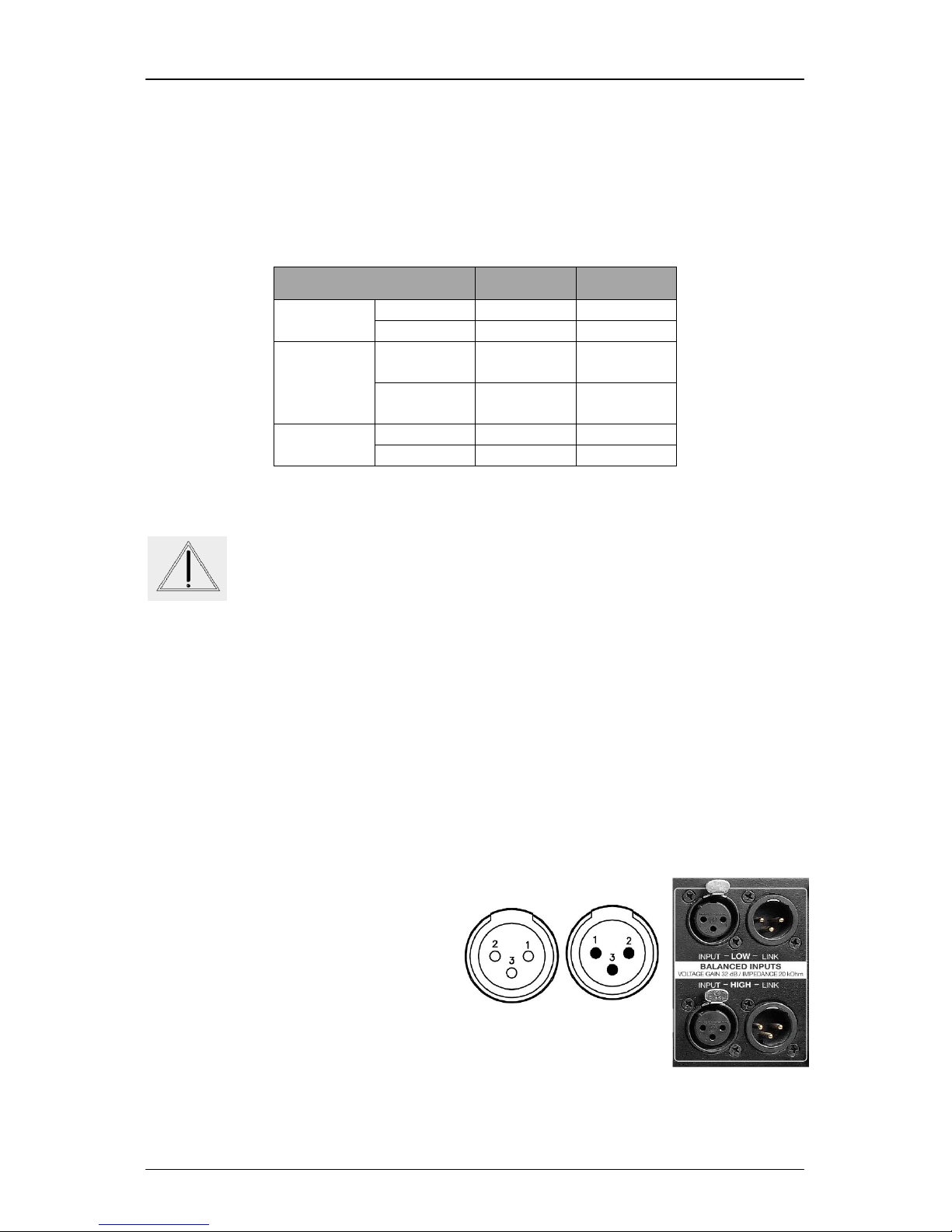
(*) NOTE: This amplifier follows the ground interconnection specification defined by
AES48-2005 standard of the Audio Engineering Society, on grounding and EMC
practices for audio equipment containing active circuitry. For that reason, when a
source with unbalanced outputs should be connected, it is recommended not
to use Pin1 of the XLR, and never connect it to Pin3. If a shielded cable is
available, the shield may be connected to Pin1 of the XLR to get some shielding,
leaving the other end unconnected. Pin1 connection is only advised if the equipment
with the unbalanced output has a dedicated connection for the shield, separate from
the audio signal ground reference.
Before powering up the unit, make sure that the input and output XLR cables are in
good state and following the above described pinning diagram, as defined by the
AES14 standard.
When connecting the XLR, please decrease the amplifier volume to the minimum
with front volume knobs until you configure the signal processing. Loudspeakers may
be damaged due to a wrong setup. It is advisable to first raise the volume of the high
frequency channels: in case they are connected to low frequency drivers by mistake,
they cannot be damaged. Otherwise, high frequency speakers may be damaged
because of trying to reproduce low frequencies. Then raise gradually the volume and
check that the system is properly connected. If so, proceed to increase the volumes
to its maximum position.
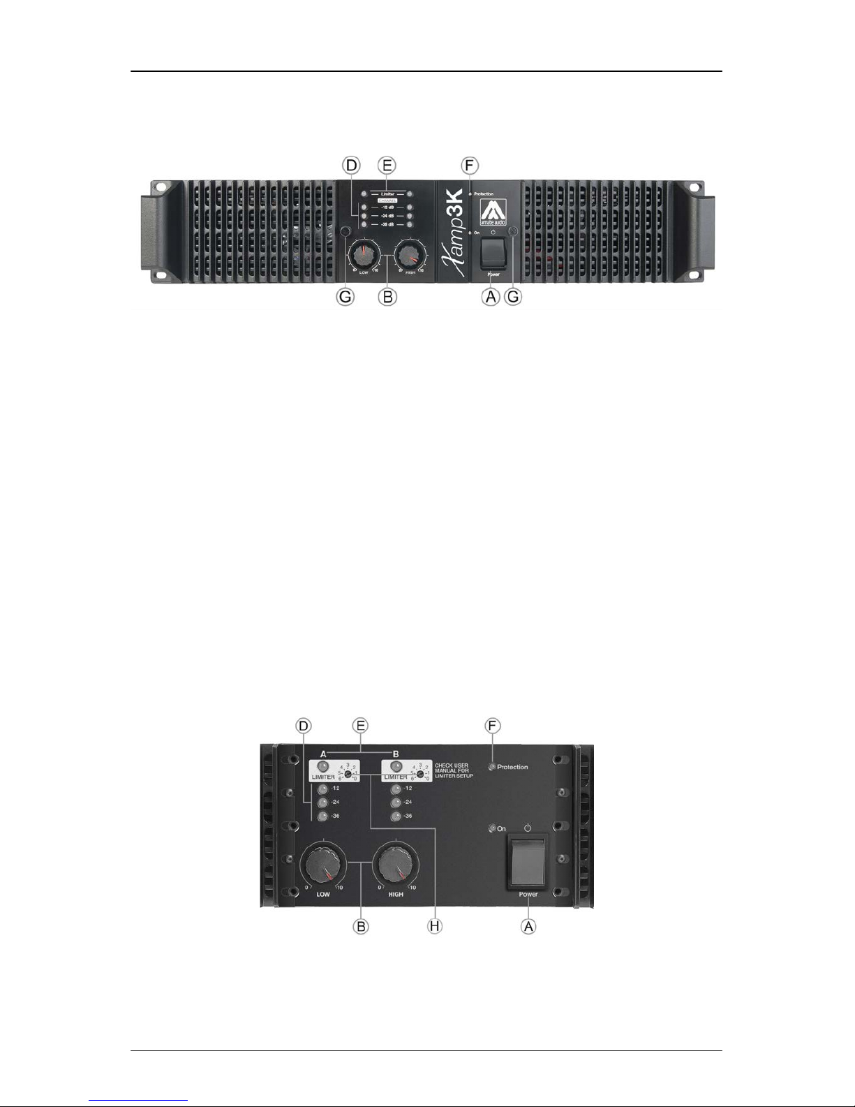
5 OPERATING THE AMPLIFIER
Along with this equipment it is necessary to use an external processing unit, for
example the DSP608, which provides to each channel the required processing to
control systems requiring independent settings for low and high (Bi-amplified).
This amplifier is designed to drive loads between 4 and 16 Ohms.
5.1 Start-up
Once the mains, loudspeaker and sound sources (input) connections have been
made correctly, start up the pre-amp sources and then press the ON/OFF switch.
Turn the volume controls clockwise to obtain the maximum gain. The amplifier is
equipped with a Soft Start circuit, which assures a gentle, pop free start up, avoiding
stress to the loudspeakers.
In order to obtain the maximum dynamic range from the amplifier, it is recommended
to set always the gain controls to the maximum, and control the output power by
regulating the signal level at the amplifier’s input using the processor gain control (in
this condition of the gain controls to the maximum, the amplification is fixed at 32dB
per channel).
5.2 Clip/Limiter
This circuit prevents the amplifier from delivering distortion at the loudspeaker
outputs. Its action is practically inaudible and protects the loudspeaker voice coils.

Xamp3K May 2016
10 Amate Audio
A LED on the front panel indicates the action of the anti-clipping limiter of each
channel. If the clip LED is lit intermittently, this may be interpreted as correct, but it
means that the amplifier is reaching its maximum power at this point.
Fig. 5. Limiter leds location on the front panel
WARNING: Make sure the LED LIMITER is not alight permanently!
No extra power is obtained in this way, losing dynamics and sound
quality.
5.3 Limiter adjustment
The amplifiers Xamp3K feature a limiter adjustment, in which the user, with an easy
adjust, can limit the output power of each output independently. Along with the DSP
input level controls and/or an external limiter, the use of this adjustment can be very
useful to protect the system in case of connection errors in XLR input or outputs
It is an easy access adjustment and it is located behind the front panel. The front
panel is fixed with two M4 screws with knurled head that can be loosen with the
fingertips. After removing the front panel you will find two LIMITER sections, one per
channel, they can be adjusted with a small flat-tip screwdriver.
Fig. 6. Limiter adjust potentiomenters on the internal front panel
The factory setting for this parameter is set to fully clockwise; this way the device
delivers its maximum power with minimum distortion thanks to its anti-clipping
system.
Each channel has an independent limiter adjustment; see the attached table of the
delivered output depending of the limiter adjustment:

Xamp3K May 2016
11 Amate Audio
Output Power
LOW Channel
HIGH Channel
16 Ω
640 W
160 W
8 Ω
1200 W
300 W
4 Ω
2400 W
600 W
16 Ω
520 W
130 W
8 Ω
950 W
250 W
4 Ω
1500 W
460 W
16 Ω
240 W
95 W
8 Ω
460 W
180 W
4 Ω
900 W
360 W
16 Ω
130 W
45 W
8 Ω
250 W
90 W
4 Ω
470 W
170 W
Table 3. Maximum output power delivery depending on limiter adjust
NOTE: The limiter adjustments and power that the amplifiers can deliver with this
adjustment are relative, because the Xamp3K amplifiers feature a dynamic limiting
system able to offers the best results.
The conditions to obtain the data in the tables have been created using 100 Hz sine
burst input signals with 100 ms at 0 dB and 400 ms at -20 dB. This condition is
considered as a standard / heavy duty in the Audio Industry.
5.4 Cooling
The Xamp3K is equipped with electronically controlled forced ventilation, which is
carried out by two turbines situated at the rear panel, one in front of each power
module. According to the temperature, two different fan speeds are set, and the hot
air is evacuated through the front panel. It is very important to favour the good air
circulation to keep the equipment in a stable temperature work pattern; therefore any
possible obstruction must be avoided both in the rear and front part. In addition, an
installation close to heat generator sources or lack of ventilation must be avoided
(closed cabinets).
WARNING: As the forced air circulation (from the back to the front) can
produce the introduction of dust and dirt in general over the internal
radiators, it is highly recommended to make an internal cleaning
operation at least once a year, depending on the particular
circumstances of each installation or use.
Any deterioration of the amplifier caused by an evident presence of dust and/or
internal humidity, will EXCLUDE of any right of application of the warranty for this
product.
5.5 Protections
Temperature
An inadequate installation or any other anomaly related to cooling may cause that
the amplifier’s temperature exceeds their safe limit (>90ºC), exposing its internal
components to failure. The temperature protection would activate the corresponding
limiters to reduce (balance) the output power with the over-temperature, in order to

Xamp3K May 2016
12 Amate Audio
keep the amplifier working safely without undesirable stops. In case the temperature
keeps rising, the corresponding protection circuit will cause a stop during a certain
time according to the seriousness of the anomaly detected. The PROTECTION and
LIMITER leds will light on at the same time, and the output of the affected channel(s)
will be disconnected.
In LOW channel, before the amplifier completely stops because of temperature
problems, it will reduce the output level by 6dB approximately. Once the temperature
reduces to normal parameters, the normal output level will be re-established.
Short circuit
In case of very low impedance or short circuit in any loudspeaker output, the
LIMITER led is activated and a significant descent of the output level of the affected
channel will be observed (loss of volume, but keeps working)
Direct Current
In the case that due to some malfunction the power module tries to deliver direct
current (DC) at the output, the protection circuit will immediately disconnect the
module to avoid damage to the loudspeakers. In that case, the PROTECTION and
LIMITER leds will light on at the same time and the output will be disconnected
Other causes that could prevent the normal work of the amplifier can also activate
the PROTECTION. Under those circumstances, the installation has to be revised
according to the basic principles described below:
• Disconnect all the connected peripheral equipment (sources, pre-amplifiers,
and loudspeakers). Leave the amplifier “alone” and verify if the anomaly
disappears or if it remains in only one channel or both.
• Temperature: Cooling (possible air obstruction. Check if the fans are working
and make an internal cleaning).
• Short circuit: Check the state of the loudspeaker line (possible short circuit,
disconnect and check if the anomaly disappears).
• C.C. at the output (DC): Possible serious breakdown. Contact an authorized
technical service.
In all cases it is recommended to go through all previous checkpoints before
contacting the authorized technical service and reporting the observed problem.

Xamp3K May 2016
13 Amate Audio
6 TECHNICAL SPECIFICATIONS
Xamp3K
Audio Input
Voltage Gain
32 dB
Input Impedance
20 kΩ
Slew Rate
+/-12 V/μs
Audio Output
Output Power (1 kHz - 0,1% THD) 1
4 Ω Load
2400 W
600 W
8 Ω Load
1200 W
300 W
LOW Channel
HIGH Channel
Frequency Response
20 Hz - 20 kHz (+0/-1 dB)
Damping Factor (1 kHz @ 8 Ω)
400
Crosstalk
65 dB
S/N Ratio (A-weighted)
108 dB(A)
Mains Supply
AC Input
220 – 240 V AC- 50/60 Hz
Average Current Draw 2
5 A @ 230 V AC
Enclosure
Dimensions (HxWxD)
88 x 482 x 440 mm
Weight
20 kg
Note (1): Continuous burst tone 20 ms (0 dB) / 480 ms (-20 dB) in accordance with
EIA RS-490 and IEC 60268-3 (IHF A-202).
Note (2): Heavy duty musical program.
Specifications subject to change without prior notice (May 2016)

Xamp3K May 2016
14 Amate Audio
ESPAÑOL
Instrucciones de seguridad
1. Todas las instrucciones de seguridad deben ser leídas antes de utilizar este
aparato.
2. El signo de exclamación dentro de un triángulo indica componentes internos cuyo
reemplazo puede afectar la seguridad.
3. El símbolo del rayo con la punta de la flecha indica la presencia de voltajes
peligrosos no aislados.
4. Este equipo no debe ser expuesto a la lluvia ni a la humedad.
5. Limpie el aparato sólo con paños secos.
6. No sitúe el equipo en lugares donde se interfiera la ventilación del aparato.
7. No instale el aparato cerca de ninguna fuente de calor, como radiadores, estufas
u otros aparatos que emitan calor.
8. Este equipo debe ser reparado por personal cualificado del servicio técnico
cuando:
A. El cable de red esté dañado, ó
B. Algún objeto o liquido haya dañado el aparato; ó
C. El equipo no funcione de una manera normal (correcta); ó
D. El equipo se haya expuesto a la lluvia; ó
E. El chasis esté dañado
9. Desconecte el aparato en caso de tormentas eléctricas o cuando no vaya a
emplearlo durante largos períodos de tiempo.
10. No cuelgue nunca el equipo por el asa.
11. Use sólo accesorios recomendados por el fabricante.

Xamp3K May 2016
15 Amate Audio
1 INTRODUCCIÓN
Amate Audio S.L. le agradece la confianza depositada en la compra de este
Xamp3K. Deseamos informarle de que todos nuestros productos incorporan las
más avanzadas tecnologías en todo su proceso de fabricación, así como la más
depurada selección de todos sus componentes, lo que nos permite garantizarle un
óptimo rendimiento y funcionalidad en cualquiera de las aplicaciones y condiciones
de trabajo a las que usted lo someta. No obstante y para obtener su máximo
rendimiento y un correcto funcionamiento, es importante leer detenidamente el
presente manual de instrucciones antes de cualquier conexión. Asimismo le
recomendamos que lea también la Carta de Garantía adjunta a este equipo por si
observara cualquier anomalía previa o inmediata a su puesta en marcha y como
proceder en su caso.
El Xamp3K es un amplificador con diseño específico para sistemas pasivos
bi-amplificados de dos vías de la serie Xcellence de Amate Audio.
Para ofrecer una configuración flexible, fiable y potente, el equipo está compuesto
de un canal en clase H de 2400 W@4 Ohms para las frecuencias bajas, más un
segundo canal de 600 W@4 Ohms para las frecuencias altas.
En combinación con el procesador de altavoces DSP608, conforman la mejor opción
para alimentar un sistema de altavoces bi-amplificado en instalaciones o situaciones
donde las soluciones autoamplificadas no son viables.
Contenido del embalaje:
- Unidad Xamp3K
- Cable de corriente AC
- Manual de usuario

Xamp3K May 2016
16 Amate Audio
2 CARACTERÍSTICAS PRINCIPALES
El diseño de nuestros amplificadores de potencia es modular. El chasis metálico de
gran rigidez y el elaborado diseño interior, permiten un fácil acceso a los circuitos
electrónicos. Los sistemas de protección, totalmente independientes, protegen al
amplificador en el caso de producirse un cortocircuito en la salida de altavoces, un
incremento anormal de la temperatura y/o un consumo excesivo del amplificador.
El amplificador Xamp3K posee una muy elevada potencia dinámica con un
moderado consumo energético medio, además de un factor damping alto, lo que se
traduce en una respuesta limpia a transitorios y una reproducción de gran calidad.
Los módulos de potencia integrados en un radiador-túnel de diseño propio, aúnan
un alto poder de disipación de calor con una excelente inercia térmica, gracias a la
gran efectividad de extracción que presentan los ventiladores incorporados
Otras características son:
- Entradas XLR balanceadas electrónicamente, para cada canal (Low & High).
- Control de volumen, limitador e indicadores VUmeter para cada vía (canal).
- Salida para cada vía mediante un único Speakon de 4 polos. Alternativamente
dispone de un Speakon adicional (en paralelo) y bornes (para cable directo).

Xamp3K May 2016
17 Amate Audio
3 CONTROLES Y CONEXIONES PRINCIPALES
3.1 El panel frontal
Fig. 7. Vista del panel frontal
A) Interruptor de puesta en marcha – Con Led indicador de “On”.
B) Control de volumen – Potenciómetros para ajustar el nivel independiente de
cada vía.
C) Salidas de ventilación – Salidas de aire forzado para refrigeración del equipo.
D) VU-Meters – Indicadores del nivel de salida independientes para cada canal, con
leds para indicar los niveles relativos de: -36dB, -24dB y -12dB.
E) Limitador – Led indicador de la función de limitador y anti-clipping.
F) Protección – Led que indica la activación de cualquiera de las protecciones
integradas, de uno o ambos canales. En la puesta en marcha es normal que se
ilumine brevemente. Si no se apaga, indica un problema en el amplificador.
G) Tornillos panel – Desenroscar (sin herramientas) para acceder al panel interno.
3.2 El panel frontal interno
Desmontar el embellecedor mediante los tornillos (G) para acceder a éste panel.
Fig. 8. Panel frontal interno
H) Ajuste del limitador – Ajuste fácil del umbral del limitador para cada canal. Para
más información ver el Capítulo “Ajuste del Limitador”.

Xamp3K May 2016
18 Amate Audio
3.3 El panel posterior
Fig. 9. Vista del panel posterior
A) Conector de red IEC / Interruptor Breaker – Entrada de red 230VAC con
protección de sobrecorriente de 10 A RMS.
B) Entrada XLR (LOW) – Balanceada electrónicamente para el canal de 2400W @
4Ohm.
C) Entrada XLR (HIGH) – Balanceada electrónicamente para el canal de 600W @
4Ohm.
D) XLR Link (Salida LOW) – Link de señal canal LOW (para otro amplificador).
E) XLR Link (Salida HIGH) – Link de señal canal HIGH (para otro amplificador).
F) Conector Speakon (OUT) – Salida para conexión de altavoces mediante
Speakon de 4 polos (bi-amp). Utilizar esta salida preferentemente.
G) Conector Speakon (LINK) – Conexión auxiliar mediante Speakon de 4 polos, en
paralelo con la principal (OUT).
H) Bornes – Salidas separadas para cada canal, conectadas en paralelo con las
salidas Speakon. Se recomienda utilizar los bornes en caso que se necesiten
cables de sección más elevada que la que admite el Speakon.
I) VENTILADORES – Turbinas para la ventilación forzada. No cubrir.
4 INSTALACIÓN
4.1 Conexión a la red
En primer lugar es necesario asegurarse de que el voltaje de red corresponde al del
equipo. Es recomendable verificar que el interruptor de puesta en marcha está en
posición apagado. El amplificador está dotado de un circuito “Soft-Start” de arranque
suave, que limita excesos de corriente en la puesta en marcha. Además, junto a la
toma de corriente se encuentra el interruptor Breaker, que protege al equipo en caso
que el consumo medio de corriente esté fuera de los parámetros normales

Xamp3K May 2016
19 Amate Audio
AC 220/240V – 50/60Hz
Consumo medio: 3 A Programa Musical
5 A Máxima Carga
PRECAUCIÓN: La conexión a un voltaje diferente del especificado
puede dañar inmediatamente el amplificador.
4.2 Conexión de altavoces
El sistema de cajas acústicas debe conectarse al conector Speakon o a los bornes,
asegurándose de que la polaridad sea la correcta. Es muy importante utilizar el
cable adecuado a la potencia del amplificador para mantener el elevado factor
damping que estas unidades ofrecen.
A título orientativo, ofrecemos una tabla de valores de la sección mínima
recomendada dependiendo de la distancia, para mantener las pérdidas de potencia
y de factor damping en valores aceptables.
Longitud cable max. recomendada
Sección del cable
Carga 8 Ohm
Carga 4 Ohm
2.5mm2 (AWG14)
20 m
10 m
4mm2 (AWG12)
30 m
15 m
6mm2 (AWG10)
40 m
20 m
8 mm2 (AWG 8)
50 m
25 m
Tabla 4. Máxima longitud de cable recomendada
Se dispone de las siguientes conexiones de salida para altavoces:
Fig. 10. Conexiones de salida para altavoces en el panel posterior
Conectores Speakon: Cada terminal puede alojar un cable de sección máxima de
4mm2 (12AWG).
• Speakon OUT: Salida principal de ambos canales. El conector speakon (no
incluído) dispone de 4 polos marcados como +1(+LOW), -1(-LOW), +2
(+HIGH), and -2(-HIGH).
• Speakon LINK: Conectado en paralelo con el Speakon OUT.

Xamp3K May 2016
20 Amate Audio
Bornes: aceptan conexión directa de cable hasta 8mm2 de sección (8 AWG). Los
Bornes están marcados con el color Rojo para el polo positivo del altavoz y con el
color Negro para el polo negativo. Se dispone de una salida separada para cada
canal: 2 bornes (rojo/negro) para LOW y otros 2 (rojo/negro) con el HIGH. Las
bornas están conectadas en paralelo con el Speakon OUT.
Las salidas están configuradas como se muestra en la tabla:
Salida
LOW
HIGH
OUT
Positivo
+1
+2
Negative
-1
-2
Bornes
Positivo
LOW
(ROJO)
HIGH
(ROJO)
Negativo
LOW
(NEGRO)
HIGH
(NEGRO)
LINK
Positivo
+1
+2
Negativo
-1
-2
Tabla 5. Configuración de los conectores de salida
PRECAUCIÓN: ¡alto riesgo de malfunción o avería
!
Según lo especificado en la configuración de las conexiones de
altavoces, existe la posibilidad de utilizar simultáneamente el OUT
SPEAKON, el LINK SPEAKON y los Bornes. Asegúrese que la carga
total conectada a cada canal no es inferior a 4 Ohms, ya que todas las salidas están
conectadas en paralelo.
Se deben extremar las precauciones al realizar las conexiones, ya que un
cortocircuito entre cualquiera de los polos positivos (1+, 2+) puede dañar el
amplificador u ocasionar averías graves como la destrucción de ambos módulos de
potencia.
4.3 Conexión de previos
Las entradas (BALANCED INPUTS) permiten la conexión mediante XLR-3. Los
amplificadores incorporan entradas balanceadas para un elevado rechazo de los
parásitos generados por cables de señal largos o cercanos a cables eléctricos o
fuentes que los provoquen, garantizando una perfecta respuesta en frecuencia.
Entradas (Input) /Salidas (Link) BALANCEADAS:
1. Malla
2. (+) Vivo
3. (–) Retorno
Entradas/Salinas NO BALANCEADAS:
1. No conectar (* Ver Nota)
2. (+) Vivo
3. Malla
Input
Link
Table of contents
Languages:
Other Amate Audio Amplifier manuals
Popular Amplifier manuals by other brands

Abbingdon Music Research
Abbingdon Music Research Dual Mono Pre-Main Amplifier AM-77 owner's manual

Inter-m
Inter-m PA-935A Operation manual

Plecter Labs
Plecter Labs Nano Biscotte v2.0 user manual

G-Wave
G-Wave BDA-PS7W-37/37-90-C Installation and operating manual

Audio-Opus
Audio-Opus Opus#11 Instruction book

Line Magnetic
Line Magnetic LM-805IA owner's manual