NITID N18W_N218W Oct 2017
3Amate Audio
1. INTRODUCTION
1.1. General
Amate Audio would like to thank you for your confidence in our NITID Series. We
suggest you to carefully read the following instructions in order to obtain the best
results in performance.
1.2. Features and presentation
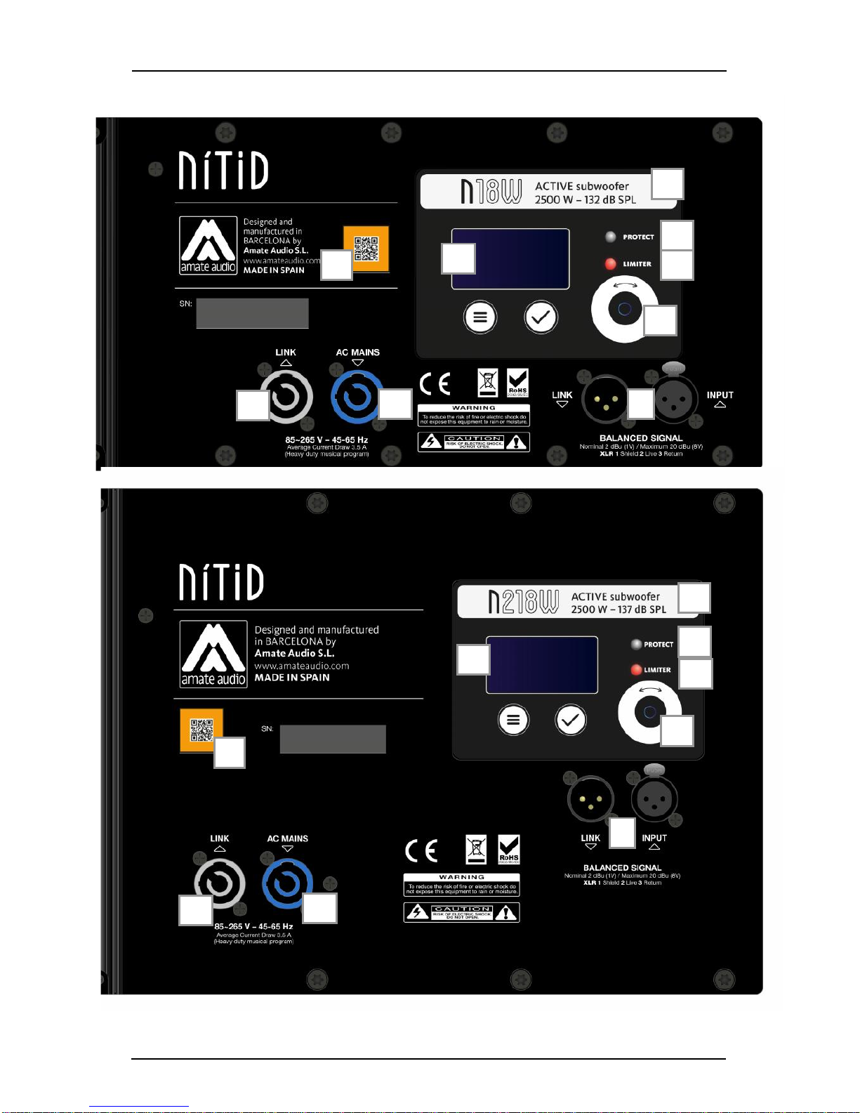
N18W
- Self-powered subwoofer
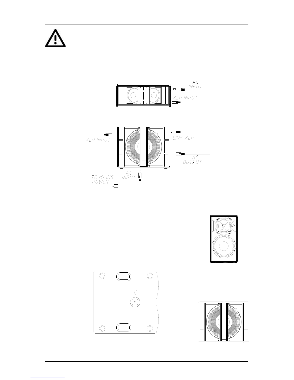
- XLR electronically balanced input & XLR parallel output
- AC PowerCon input and link
- 2500 W Class-D amplifier
- 24-bit AD/DA converters, 48 kHz sampling rate
- Self amplifier diagnostics: output power, temperature, clipping
- DSP Controls (delay, volume, PEQ, presets, polarity and limiter)
- 18” woofer with 4” voice coil
N218W
- Self-powered subwoofer
- XLR electronically balanced input & XLR parallel output
- AC PowerCon input and link
- 2500 W Class-D amplifier
- 24-bit AD/DA converters, 48 kHz sampling rate
- Self amplifier diagnostics: output power, temperature, clipping
- DSP Controls (delay, volume, PEQ, presets, polarity and limiter)
- 2 x 18” woofers with 4” voice coil
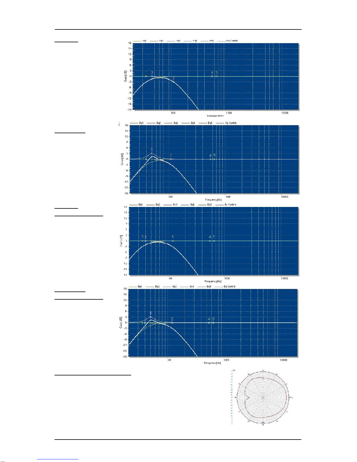
1.3. Presets on N18W, N218W
The N18W and N218W include several manufacturer presets for different types of
applications.
ATTENTION: When the N18W or N218W are used in conjunction with the Full-range
NITID systems in SPEECH or XOVER presets, the N18W and N218W must operate
in positive polarity.
When the N18W or N218W are used in conjunction with the Full-range NITID
systems in FLAT, NEARFIELD, LONGTHROW, SMOOTH, MONITOR presets, the
N18W and N218W must operate in negative polarity.
LPF80
80 Hz low pass filter