manuals.online logo
Brands
  1. Home
  2. •
  3. Brands
  4. •
  5. Ambassade de Bourgogne
  6. •
  7. Cooker
  8. •
  9. Ambassade de Bourgogne CG 731 G Configuration guide

Ambassade de Bourgogne CG 731 G Configuration guide

This manual suits for next models

2

Other Ambassade de Bourgogne Cooker manuals

Ambassade de Bourgogne CSG 420 R User manual

Ambassade de Bourgogne

Ambassade de Bourgogne CSG 420 R User manual

Ambassade de Bourgogne CG 721 GAGCF User manual

Ambassade de Bourgogne

Ambassade de Bourgogne CG 721 GAGCF User manual

Popular Cooker manuals by other brands

Logik LFTG50A12 installation manual

Logik

Logik LFTG50A12 installation manual

Smeg SUK61CMA5 user manual

Smeg

Smeg SUK61CMA5 user manual

Rayburn 200G/L Gas Fired Cooker Installation and servicing instructions

Rayburn

Rayburn 200G/L Gas Fired Cooker Installation and servicing instructions

VacPak-It SV158 manual

VacPak-It

VacPak-It SV158 manual

Electrolux N7E Installation and operating manual

Electrolux

Electrolux N7E Installation and operating manual

Electrolux EKE6100 Instruction book

Electrolux

Electrolux EKE6100 Instruction book

ARO SHC5065 instruction manual

ARO

ARO SHC5065 instruction manual

Baumatic BCE905SS user manual

Baumatic

Baumatic BCE905SS user manual

Bosch HCE744350R instruction manual

Bosch

Bosch HCE744350R instruction manual

Modena FC 7645 SGM User manual book

Modena

Modena FC 7645 SGM User manual book

Stanley Donard 60 Installation and operating instructions

Stanley

Stanley Donard 60 Installation and operating instructions

Bartscher 201TC manual

Bartscher

Bartscher 201TC manual

Parkinson Cowan 50 GR/BU installation instructions

Parkinson Cowan

Parkinson Cowan 50 GR/BU installation instructions

Creda S150E Installation and user instructions

Creda

Creda S150E Installation and user instructions

Creda HB48309 instructions

Creda

Creda HB48309 instructions

Bosch HCE743220F instruction manual

Bosch

Bosch HCE743220F instruction manual

Tricity Bendix SE545P manual

Tricity Bendix

Tricity Bendix SE545P manual

NEFF E1461A2/01 Instructions for use

NEFF

NEFF E1461A2/01 Instructions for use

manuals.online logo
manuals.online logoBrands
  • About & Mission
  • Contact us
  • Privacy Policy
  • Terms and Conditions

Copyright 2025 Manuals.Online. All Rights Reserved.

«CG 731-741 »
«CG 731 CF »
MANUEL GENERAL
GENERAL MANUAL
ALGEMENE HANDLEIDING
AMBASSADE
DE BOURGOGNE
Date de mise à jour : 07/10/2014 - FT006 - Révision 09- FR / GB / NL Page 1 sur 20
AMBASSADE
DE BOURGOGNE
CG 731 G/ CG 731 CF/ G 741 G
FR
Accessoires
GB
Accessories
NL
Accessoires
1 grille / shelf / inschuifrooster - 1 tôle pâtisserie / pastry tray / bakplaat
SOCIETE INDUSTRIELLE DE
LACANCHE
Tél. :03.80.90.35.00 - Fax : 03.80.84.24.92
Société anonyme au capital de 150.000 €
Adhérent SYNEG
FR
GB
DIMENSIONS
NL
AFMETINGEN
Dimensions extérieures (L x P x H)
External dimensions (L x W x H )
Uitwendige afmetingen (B x D x H)
700 x 650 x 900
Poids Brut / gross weight / Bruto gewicht
97 kg
Poids Net / Net weight / Netto gewicht
83 kg
Colisage
Packaging
Verpackking
Carton/ palette bois
Carton-woodenpalette
Karton-houden palet
FR
GB
CONSTRUCTION
NL
KONSTRUKTIE
Carosserie / Body / Karosserie
Acier inoxydable/ Stainless Steel / RVS
Table / Cooking surface /Kooktafel
Acier / Steel / Staal Z7CN 18.10
Façade / Front / Voorkant
Acier / Steel / Staal Z8C17
Four / Oven
Acier émaillé ou /Enamelled steel or / Geèmailleerd oderacier / steel / staal Z8C17
Arrière / Behind / Achterkant
Aluzinc AZ 150
Corps de brûleur / Burner body / Branderschacht
Aluminium AS 12
Tête de brûleur / Burner cap / Branderkop
Laiton / Brass / Messing
FR
GB
Directives
NL
Instrukties
Appareils à gaz
Gas appliances Gasapparaat
2009/12/CEE
Basse Tension / Low Voltage /
Zwakstroom
2006/95/CEE
CEM
2004/108/CEE
Raccordement gaz
Gas connection
Gasaansluiting
Raccordement électrique
Electric connection
Elektrische aansluiting
700
650
900
930
420
600
305
530
335
840
P / F
530
A
150 (175)
50
1020
90
Fig. 1
40
Date de mise à jour : 07/10/2014 - FT006 - Révision 09- FR / GB / NL Page 2 sur 20
FR
DONNES TECHNIQUES
GB
TECHNICAL DATA
NL
TECHNISCHE GEGEVENS
FOUR GAZ / GAS OVEN ( F )
Nombre / Number / Aantal
1
Dimensions (L x P x H) / Dimensions ( L x W x H)
Afmetigen (B x D x H)
530 x 460 x 305 mm
Nombre de niveaux / Number of levels / Aantal van niveaus
4 espacés de58 mm/ 4 with aspaceof 58 mm/ 4 onderlingeafstand 58 mm
Allumage / Ignition / Ontsteking
Manuel / Manuel / Handmatig *
Surveillance de flamme / Fire control / Vlamkontrole
Thermocouple / Thermokoppel
BRÛLEURS / BURNERS / BRANDERS (UR - I- R - SR)
Nombre / Number / Aantal CG 731 G/ CG 731 CF
3
Nombre / Number / Aantal CG 741 G
4
Allumage / Ignition / Ontsteking
Manuel / Manuel / Handmatig *
Surveillance de flamme / Fire control / Vlamkontrole
Thermocouple / Thermokoppel
PRESSIONS ET CONSOMMATIONS HORAIRE / PRESSURES AND HOURLY CONSUMPTION/
DRUKWAARDEN EN ENERGIEVERBRUIK PER UUR
Tableau 2, annexe 2 – Table 2, appendix 2 – Tabel 2, bijlage 2.
RACCORDEMENT GAZ / GAS CONNECTION / GASAANSLUITING
Tube Ø 15/21, filetage 1/2" gaz sur raccord femelle / Tube Ø 15/21, 1/2" gas thread, on female coupling.
Leiding Ø 15/21, schroefdraad 1/2" voor gasaansluiting, met vrl. koppeling.
FR
OPTIONS ELECTRIQUES
GB
ELECTRICAL OPTIONS
NL
ELEKRISCHE OPTIES
FOUR STATIQUE / STATIC OVEN / STATISCH OVEN
Dimensions (L x P x H) / Dimensions ( L x W x H)
Afmetigen (B x D x H)
530 x 460 x 305
Sole / Base / Bodemplaat
1,9 kW + 1,2 kW = 3,1 kW
Grill
2,85 kW
Sécurité / Safety / Veiligheid
Thermostat de sécurité / Safety thermostat / Begrenzingsthermostaat.
Alimentation / Supply / Voeding
230 V 1N~ 50 Hz + T / 400 V 3N~50 Hz + T.
FOUR VENTILÉ / VENTILATED OVEN / GEVENTILEERDE OVEN.
Dimensions (L x P x H) / Dimensions ( L x W x H)
Afmetigen (B x D x H)
530x405x305
Sécurité / Safety / Veiligheid
Thermostat de sécurité / Safety thermostat / Begrenzingsthermostaat.
Puissance / Rating / Kapaciteit
3,4 kW.
Grilloir / Grill (option / optie)
2,85 kW.
Alimentation / Supply / Voeding
230 V 1N~ 50 Hz + T / 400 V 3N~50 Hz + T.
RACCORDEMENT ELECTRIQUE / ELECTRIC CONNECTION / ELECTRISCHE AANSLUITING
Sur bornier au dos de l’appareil / On terminal block at the rear of the appliance / Op klemblok aan de achterkant van het apparaat.
ALLUMAGE ELECTRIQUE /ELECTRIC IGNITION / ELEKTRISCHE ONTSTEKING
*
Allumage électrique des brûleurs de table et de four par bouton poussoir / Pushbutton cooktop and oven electric
ignition / Elektrische ontstekingsknop voor kookplaat en oven
RACCORDEMENT ELECTRIQUE / ELECTRIC CONNECTION / ELECTRISCHE AANSLUITING
Sur bornier au dos de l’appareil / On terminal block at the rear of the appliance / Op klemblok aan de achterkant van
het apparaat.
FR
Accessoires
GB
Accessories
NL
Accessoires
Par four / Per oven / Met oven : 1 grille, une tôle pâtisserie –one shelf, one pastry tray per oven -een inschuifrooster, een
bakplaat.
Date de mise à jour : 07/10/2014 - FT006 - Révision 09- FR / GB / NL Page 3 sur 20
«CG 731-741 »
«CG 731 CF »
MANUEL D’INSTALLATION
INSTALLER’S MANUAL
INSTALLATIEHANDLEIDING
AMBASSADE
DE BOURGOGNE
FR
L’installation doit se faire selon les règles de l’art conformément aux instructions contenues dans
cette notice et les règlements en vigueur dans le pays d’installation.
Ce manuel sera remis à l’utilisateur après installation.
GB
Appliances must be installed in a workmanlike manner in accordance with the instructions in this
manual and locally applicable regulations.
This manual will be handed over to the user after installation.
NL
De apparaten moeten volgens de in het betreffende land geldende wetten en voorschriften worden
geïnstalleerd, met strikte inachtneming van de instrukties uit deze handleiding.
Deze handleiding moet na het installeren aan de gebruiker overhandigd worden.
Date de mise à jour : 07/10/2014 - FT006 - Révision 09- FR / GB / NL Page 4 sur 20
IMPLANTATION / SITING
PLAATSING
FR
Installer impérativement sous une hotte d’extraction.
Si cet appareil doit être mis en place près d’un mur, d’une cloison, d’un meuble, de bordures décoratives. Il est
recommandé que ceux -ci soient faits d’un matériau non combustible. Si ce
n’est pas le cas, ils doivent être recouverts
d’un matériau approprié, bon isolant thermique non combustible. Une attention toute spéciale étant accordée aux
réglementations de prévention des incendies.
GB
Must be installed under an extractor hood.
Do not install this unit near combustible walls, partitions, pieces of furniture or decorative material unless these are
covered with adequate thermal insulation of the noncombustible type. Making sure the resulting installation meets
local fire regulations.
NL
Moet verplicht onder een afzuigkap worden geplaatst.
Dit kooktoestel mag uitsluitend in de nabijheid van brandbare muren, scheidingswanden, keukenmeubels, sier- of
ander materialen worden geplaatst wanneer deze bedekt dan wel overtrokken zijn met brandwerend isolatiemateriaal.
De aldus ontstane installatie dient te voldoen aan de plaatselijke voorschriften t.a.v. brandveiligheid.
FR
Déballer, vérifier le bon état de l’appareil. En cas d’avaries, signifier les réserves sur le bordereau de livraison,
les confirmer, au plus tard sous 48 heures, par lettre recommandée avec accusé de réception auprès du transporteur.
GB
Unpack and check the appliance is in good condition. In case of damage, note any reservations on the delivery note
and confirm them within 48 hours by registered letter with confirmation of delivery to the carrier.
NL
Pak het apparaat uit en controleer of het in goede staat verkeert. Signaleer eventuele beschadigingen op de
leveringsbrief, en bevestig deze reserves binnen 48 uur per aangetekende brief met bericht van ontvangst aan de
transporteur.
FR
Avant toute utilisation, il est impératif d’enlever toute les protections plastiques intérieures et extérieures sous
peine de dommages irréversibles aux parois aciers.
GB
Before use, it is mandatory to remove all the internal and external plastic packing pieces, failure to do so will
cause irreversible damage to the steel walls.
NL
Voor elk gebruik moeten alle plastic beschermonderdelen aan binnen- en buite
nkant verwijderd worden, omdat
anders de stalen wanden onherstelbaar beschadigd raken.
FR
Toute intervention ou dépannage sur un appareil doit être effectuée par un installateur qualifié.
GB
All work on or repair of an appliance must be carried out by a qualified installer.
NL
Alle onderhouds-
en reparatiewerkzaamheden aan deze apparaten moeten worden uitgevoerd door een
gekwalificeerde installateur.
Date de mise à jour : 07/10/2014 - FT006 - Révision 09- FR / GB / NL Page 5 sur 20
Tableau
Type
Pression / Pressure / Druk
m3/h/kW
Table
G 20
20 mbar
1,46
Tabel
G 25
20 mbar
1,60
1
G 25
25 mbar
1,60
G 30
28-30 mbar
1,12
G 30
50 mbar
1,12
G 31
37 mbar
1,39
G 31
50 mbar
1,39
FR
L’ INSTALLATION DOITETRE REALISEE CONFORMEMENT AUXREGLEMENTATIONS ET NORMES EN VIGUEUR .
GB
THE APPLIANCE MUST BE INSTALLED IN ACCORDANCE WITH THE APPLICABLE REGULATIONS AND STANDARDS.
NL
DE APPARATENMOETENVOLGENS DE GELDENDE DE WEITTEN EN VOORSCHRIFTEN WORDEN GEINSTALLEERD.
FR
Nota : Cet appareil est de type Anon
raccordé à un conduit d’évacuation.
GB
Note : This is a type A
appliance and is not
connected to a ventilating flue.
NL
N.B.: Dit apparaat is van het type A- niet
aangesloten op een afvoerleiding.
GAZ / GAS IMPORTANT/ BELANGRIJK
 Avant raccordement / Before connection / Voor het aansluiten Vérifier / Check / Eerst
controleren :
FR
Le parfait état de propreté des canalisations, afin d’éviter l’obstruction des injecteurs et le
dysfonctionnement des têtes magnétiques. Le gaz pour lequel l’appareil à été réglé : plaquette signalétique (A fig. 1) et
marquage. La compatibilité
de la section des canalisations d’alimentation avec la puissance de l’appareil (voir annexe
2). La conformité du débit d’air neuf (voir tableau 1).
GB
Pipework is perfectly clean in order to prevent the injectors becoming blocked and malfunctioning of the
magnetic heads. The gas for which the appliance was set up: rating plate (A fig. 1) and markings. Cross-
sectional area
of gas supply pipework is compatible with the appliance’s thermal output (see Appendix 2).
Correct fresh air flowrate
(See table 1).
NL
Of de buisleidingen volkomen schoon zijn, om verstopping van de injectors en storingen in de
werking van
de magneetkoppen te voorkomen. Voor welk soort gas het apparaat is ingesteld: zie konstruktieplaatje (A
fig. 1) en
markering. Of de doorsnede van de t
oevoerbuizen afgestemd is op het vermogen van het apparaat (zie bijlage 2).
Juiste doorvoerhoeveelheid verse lucht (zien tabel 1).

Raccordement / Connection / Aansluiten
FR
Raccord femelle Ø 15/21, filetage 1/2” gaz (fig. 1). L'arrivée de gaz n'est pas réversible.
GB
Female coupling Ø 15/21, 1/2” gas thread (fig. 1). The gas supply connection is non-reversible as supplied.
NL
Vrl. koppeling Ø 15/21, schroefdraad 1/2” gas (fig. 1). De gasaansluiting wordt niet-omkeerbaar geleverd.
2a
2b
3
Date de mise à jour : 07/10/2014 - FT006 - Révision 09- FR / GB / NL Page 6 sur 20

Ouverture du dessus / To remove top / Blad losnemen
FR
Dévisser les vis (fig. 2a, 2b). Dévisser les vis (fig. 3) situées près des ouvertures des brûleurs.
GB
Unscrew the screws (fig. 2a, 2b). Unscrew screws (fig. 3) near the burner openings.
NL
Draai de schroeven (fig. 2a, 2b). Neem de schroeven (fig. 3) naast de branderopeningen los,

Après raccordement / After connection / Na het aansluiten
FR
Lever le dessus et c
ontrôler la pression d’alimentation sur prise de
pression (A, fig. 4 ).
GB
Raise the top and check the supply pressure o
n pressure connection
(A, fig. 4).
NL
Trek de bovenplaat eraf, los en controleer de toevoerdruk op
drukmeetnippel (A, fig. 4).
4
A
Date de mise à jour : 07/10/2014 - FT006 - Révision 09- FR / GB / NL Page 7 sur 20
CHANGEMENT DE GAZ / CHANGE OF GAS/
OVERSCHAKELEN OP ANDERE GASSOORT
FR
En cas d’utilisation avec un gaz autre que celui du réglage initial, il est impératif
de procéder à l’échange des
injecteurs et de reprendre les réglages comme définis ci-après
GB
In case of use with a gas other than that for which the appliance was initially set up, it is crucial
to replace the
injectors and modify the adjustments as defined below and.
NL
Als een ander gas gebruikt wordt dan dat waarvoor het apparaat oorspronkelijk was ingesteld, is het absoluut
noodzakelijk de injectors te verwisselen en het apparaat opnieuw in te stellen volgens onderstaande instrukties.
FR
L’appareil est prévu pour fonctionner avec les gaz
du tableau 4 (Annexe 2).
GB
The appliance is designed to operate with the gases
in Table 4 (Appendix 2)..
NL
Het apparaat werkt op de in onderstaande tabel 2
(Bijlage 4) aangegeven gassoorten.
IMPORTANT / BELANGRIJK
FR
Fermer le robinet de barrage avant toute
intervention .
GB
Close the mains gas tap before carrying out any
work.
NL
Draai de afsluitkraan dicht voordat de volgende
handelingen worden uitgevoerd.
IMPORTANT / BELANGRIJK
BRULEURS DE TABLE / HOB BURNERS / KOOKTAFELBRANDERS
B
C
E
D
F
5
G

FR
Spécial U.K :
L’appareil prévu pour être relier à un circuit en gaz naturel est équipé d’un régulateur de pression gaz permettant à
cet appareil de fonctionner sous une pression de 15 mbar.
Dans le cas d’un changement de gaz, il est nécessaire de retirer ce régulateur de pression et d’alimenter l’appareil en
gaz butane ou propane directement au point de raccordement de l’alimentation gaz de l’appareil.
Procéder, comme lors de tout changement de gaz, aux nouveaux réglages (injecteurs, air primaire, …). Voir annexe
technique 2.

GB
Spécial U.K :
The oven is designed to run on natural gas and is therefore fitted with a pressure regulating valve that allows it to be
used at a pressure of 15 mbar.
If a different type of gas is to be used, this pressure regulating valve must be removed and the gas supply connected
directly to a source of butane or propane.
As always when changing the type of gas, the injectors, primary air, etc. must be adjusted. See technical appendix 0.
Date de mise à jour : 07/10/2014 - FT006 - Révision 09- FR / GB / NL Page 8 sur 20
Changement de l’injecteur / Changing nozzle / Spuitstuk vervangen (fig. / afb 5) :
FR
Relever les bagues d’air B. Remplacer les injecteurs Csuivant tableau 5 en annexe 2 ( Ø en 1/100mm).
Les corps des brûleurs latéraux sont maintenus par une traverse D. Pour les dégager, dévisser les vis Epuis la vis F.
Nota : Lors du remplacement d’un (des) injecteur(s), remplacer également la rondelle d’étanchéité (voir
schéma de
gazage).
GB
Lift the air ring B. Replace the injectors Cin accordance with Table 5 in appendix 2 (Ø in 1/100 mm).
The side burner bodies are kept in place by a transversal bar (D). In order to take them out, unscrew screws Ethen F.
Note : When one or more nozzles are changed, the sealing ring should be changed as well (see gas circuit diagram).
NL
Verwijder luchtring B. Vervang de spuitstukken C
aan de hand van tabel 5 bijlage 2 (diameters zijn in
honderdsten van millimeters).
De zijbranders worden met een dwarsbalk (D) op hun plaats gehouden. Neem eerst schroef Een daarna schroef Flos
om de branders los te nemen.
N.B. : Wanneer een of meer spuitstukken vervangen worden moet de dichtingsring eveneens vervangen worden (zie
het gascircuitschema).

Réglage de l’air primaire / Adjustment of primary air / Instellen van primaire luchtstroom
FR
Reposer corps et chapeaux de brûleurs dans leur cuvette respective, régler la bague d’air du brûleur (voir fig. 5, tableau
6, annexe 2). Nota:Des flammes normales ont une couleur bleu-vert, sauf pour le gaz naturel où elles sont violettes.
GB
Refit the burner bodies and burner caps in their respective recesses, adjust the air ring of the burner (see fig. 5, table
6, appendix 2). Note : Normal flames are bluish green except for natural gas flames which are violet.
NL
Plaats schacht en dop van elke brander in de betreffende opening, en stel de luchtring van de branders in (zie fig. 5, tabel
2, bijlage 2). N.B.:Normale vlammen hebben een groenblauwe kleur. Aardgas geeft een paarse vlam.

Réglage du débit réduit des brûleurs de table / Adjustment of reduced flowrate of hob burners /
Instellen van minimumstand kooktafelbranders
FR
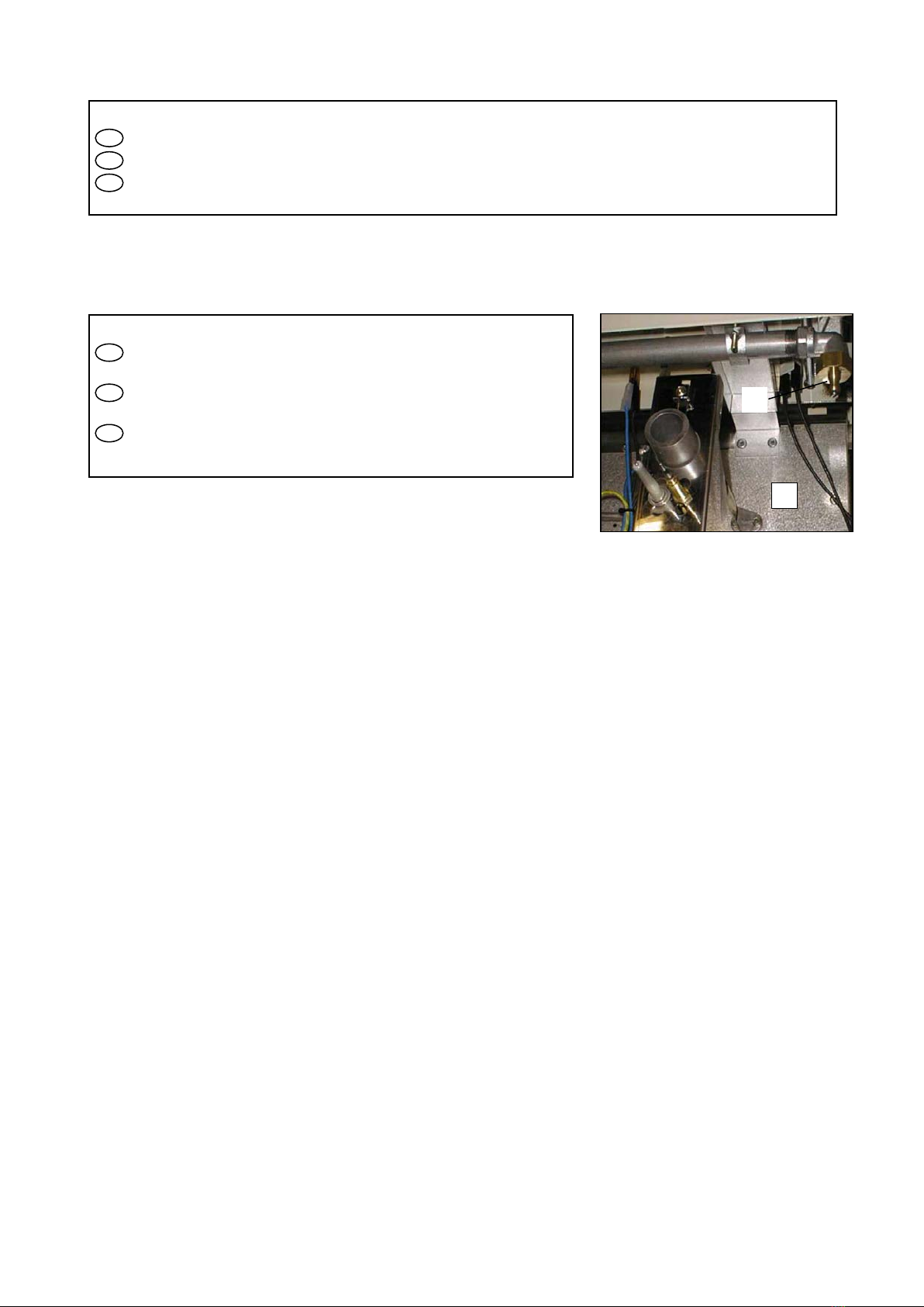
Après raccordement ou changement de gaz, il est impératif
de reprendre ce réglage. Déposer la manette,
allumer le brûleur, passer en position min., puis agir à l’aide d’un tournevis sur la vis de réglage H (fig. 6).
Nota: les flammes sont réduites au ¼ de leur taille en position mini, le brûleur ne doit pas s’éteindre en passant de la
position maxi à la position mini.
GB
After connection or change of gas, it is crucial to modify this adjustment. Remove the control knob, light the
burner, adjust to minimum setting, then use a screwdriver to set the adjusting screw H(fig. 6).
Note: flame is reduced to ¼ of its size in the minimum setting, the burner must remain lit when changing from
maximum setting to minimum setting.
NL
Na het aansluiten of na het overschakelen op een andere gassoort, is het absoluut noodzakelijk de
minimumstand van elke brander opnieuw in te stelle
n. Verwijder de bedieningsknop, steek de brander aan, zet hem op
minimumstand en draai de stelschroef Hin de gewenste stand met behulp van een schroevedraaier (fig. 6).
N.B.: in minimumstand worden de vlammen teruggebracht tot een 1/4 van hun grootte. Bij
het overgaan van
maximum- naar minimumstand mag de brander niet uitgaan.
H
6
BRULEURS DE FOUR / OVEN BURNERS /
OVENBRANDERS
Injecteur de four / Oven injector
FR
Retirer la sole, ATTENTION
lors de la repose, bien la
ramener sous le pli de la façade (fig. 7).
Désaccoupler la tubulure, dévisser la vis du porte injecteur I
(fig. 6).
Echanger l’injecteur J(tableau n° 7, annexe 2).
GB
Remove the base, CAUTION:
when refitting place the base
underneath the groove on the fascia (Figure 7).
Disconnect the connection piece, unscrew screw on the injector
holder I (Figure 6). Replace the injector J(Table 7, appendix 2).
NL
Verwijder de bodemplaat. LET OP: bij hermontage de plaat
juist aanbrengen, onder de frontrichel (fig. 7).
Koppel de buisleiding los, draai schroef van de injectorhouder Ilos
(fig. 6). Verwissel de injector J(tabel n° 7, bijlage 2).
Date de mise à jour : 07/10/2014 - FT006 - Révision 09- FR / GB / NL Page 9 sur 20
Réglage de l’air primaire four / Adjustment of oven primary airflow Instellen van primaire luchtstroom oven
FR
Dévisser la vis de maintien de la bague d’air K, procéder au réglage (voir fig. 8, tableau 7, annexe 2).
GB
Loosen the screw that secures the air ring Kand then adjust (see fig. 8, table 7, appendix 2).
NL
Verwijder de bodemplaat. Draai de borgschroef van de luchtring Klos en stel de luchtstroom in (zie fig. 8, tabel 7,
bijlage 2).
Réglage du débit réduit de four Adjustment of oven reduced flowrate Instellen van minimumstand oven
FR
IMPERATIF après raccordement et tout changement de gaz.
Vis de réglage accessible après dépose de la
manette de commande (fig. 9).
Allumer le brûleur co
rrespondant, préchauffer le four environ 1/4 d’heure (thermostat 10), passer en position mini
(thermostat 1), puis agir à l’aide d’un tournevis sur la vis L(agir
rapidement avant que le thermostat ne réagisse
et que le brûleur ne repasse au débit maximun). Nota: les flammes sont réduites au ¼ de leur taille en position maxi, le
brûleur ne doit pas s’éteindre en passant de la position maxi à la position mini.
GB
Adjustment is VITAL after connection or any change of gas. The adjusting screw is accessed by removing the
control knob (Figure 9).
Light the appropriate burner, pre-
heat the oven for roughly 1/4 hour (thermostat 10), adjust to minimum setting
(thermostat 1), then use a screwdriver to set the adjusting screw L(do this quickly before the thermostat
responds and
the burner returns to the maximum setting). Note: flame is reduced to ¼ of its size in the maximum setting, the burner
must remain lit when changing from maximum setting to minimum setting.
NL
ABSOLUUT NOODZAKELIJK na het aansluiten of na het o
verschakelen op een andere gassoort.
Stelschroef toegankelijk na het verwijderen van de bedieningsknop (fig. 9).
Steek de betreffende brander aan, verwarm de oven een kwartier voor (thermostaat 10), en zet hem vervolgens op
minimumstand (thermostaat 1). Draai nu de stelschroef L
in de gewenste stand met behulp van een kleine
schroevedraaier (dit moet snel gebeuren, voordat de thermostaat reageert en de brander overschakelt op
maximumstand). N.B.: de vlammen worden teruggebracht tot 1/4 van hun grootte in maximumstand.
Bij het
overschakelen van maximum- naar minimumstand mag de brander niet uitgaan.
Réglage des sécurités par thermocouple Adjustment of thermocouple safety cut-outs Instellen van de
thermokoppelbeveiligingen.
FR
Si le brûleur s’éteint, après avoir maintenu enfoncée à fond la manette une vingtaine de secondes; vérifier : Le
serrage (modéré) de la tête magnétique sur le robinet, que la pointe du thermocouple Gsoit bien léchée p
ar la flamme
(fig. 5 &8) et le bon état de propreté des thermocouples et têtes magnétiques.
GB
If the burner goes out, having kept the control knob pushed in for roughly twenty seconds, check : (Moderate)
tightening of magnetic head on the valve, the thermocouple Gtip actually touches the flame (Figure 5 &8). and the
thermocouples and magnetic heads are clean.
NL
Als de brander uitgaat nadat u de knop twintig sekonden lang ingedrukt hebt gehouden moet gecontroleerd
worden : Of de magneetkop goed op de kraan is vastgedraaid (matig vast), of de vlam goed aan de punt van het
thermokoppel Glekt (fig. 5 &8). en of thermokoppels en magneetkoppen volkomen schoon zijn.
Dépose
Videre
insetzen
Sistemazione
Repose
Herausnehmen
Rimozione
7
8
L
9
Date de mise à jour : 07/10/2014 - FT006 - Révision 09- FR / GB / NL Page 10 sur 20