ambiq micro Apollo3 Blue Plus User manual

Apollo3 Blue Plus EVB Quick Start Guide
Ultra-Low Power Apollo MCU Family
QS_A3P_1p1 Page 1 2020 Ambiq Micro, Inc.
All rights reserved.
Apollo3 Blue Plus EVB
Board Revision 1.0
Quick Start Guide
Doc. ID: QS_A3P_1p1
Document Revision 1.1
July 2020

Apollo3 Blue Plus EVB Quick Start Guide
Ultra-Low Power Apollo MCU Family
QS_A3P_1p1 Page 2 2020 Ambiq Micro, Inc.
All rights reserved.
Table of Content
Introduction ................................................................................................................. 5
Document Revision History......................................................................................... 5
Overview of the Apollo3 Blue Plus EVB...................................................................... 6
Debug Interface .......................................................................................................... 8
Software Development Tools.................................................................................... 10
Power Supply Options and Measuring Current......................................................... 11
FTDI Interface........................................................................................................... 14

Apollo3 Blue Plus EVB Quick Start Guide
Ultra-Low Power Apollo MCU Family
QS_A3P_1p1 Page 3 2020 Ambiq Micro, Inc.
All rights reserved.
List of Figures
Apollo3 Blue Plus EVB, Revision 1.0.......................................................................... 6
Apollo3 Blue Plus EVB Parts Location........................................................................ 6
Apollo3 Blue Plus EVB’s Cortex DEBUG IN Header (J1)........................................... 8
Apollo3 Blue Plus EVB’s DEBUG OUT Header (J2)................................................... 9
Apollo3 Blue Plus EVB’s DEBUG OUT LED (D3)....................................................... 9
Voltage Selection on Header P19............................................................................. 11
Header P19 Configured for 3.3V Operation - No Current Measurement .................. 12
Header P19 Configured for 3.3V Operation - With Current Measurement ............... 12
Solder Bridge SB1 .................................................................................................... 13

Apollo3 Blue Plus EVB Quick Start Guide
Ultra-Low Power Apollo MCU Family
QS_A3P_1p1 Page 4 2020 Ambiq Micro, Inc.
All rights reserved.
List of Tables
Document Revision History......................................................................................... 5
Jumper Configuration for Power Selections.............................................................. 11

Apollo3 Blue Plus EVB Quick Start Guide
Ultra-Low Power Apollo MCU Family
QS_A3P_1p1 Page 5 2020 Ambiq Micro, Inc.
All rights reserved.
1. Introduction
This document provides guidance in setting up the Apollo3 Blue Plus Evaluation Board (EVB), part number
AMA3B2EVB, revision 1.0, to get started executing code examples, measuring power consumption in
various configurations, and beginning software development.
RF Certification Information
Model PIN: AMA3B2EVB
Product Name: AMA3B2EVB
FCC ID: 2APPJ2102154167100
CMIIT ID: 2020DP3158(M)
TELEC No.: 201-200123
Ambiq Micro, Inc.
2. Document Revision History
Rev # Date Description
1.0 December 2019 Document initial public release
1.1 July 2020 RF certification information added
Table 1: Document Revision History
ᜠಸ⛉㸦῝ᆆ㸧䔜⬷㛰昷⅓⏟

Apollo3 Blue Plus EVB Quick Start Guide
Ultra-Low Power Apollo MCU Family
QS_A3P_1p1 Page 6 2020 Ambiq Micro, Inc.
All rights reserved.
3. Overview of the Apollo3 Blue Plus EVB
The Apollo3 Blue Plus EVB features Arduino-compatible headers and an integrated J-Link debugger:
Figure 1. Apollo3 Blue Plus EVB, Revision 1.0
Figure 2. Apollo3 Blue Plus EVB Parts Location

Apollo3 Blue Plus EVB Quick Start Guide
Ultra-Low Power Apollo MCU Family
QS_A3P_1p1 Page 7 2020 Ambiq Micro, Inc.
All rights reserved.
The EVB has these additional features:
▪ Low power reference design
▪ Apollo3 Blue Plus MCU in the BGA package (AMA3B2KK-KBR)
▪ Multiple power/clock options
▪ Micro USB Type C connector for power/download/debug
▪ On-board PCB (MIFA) antenna
▪ FTDI USB-to-SPI adapter/interface
▪ RF switch/connector (J1 - Murata MM8430-2610RA1) for BLE PHY testing
▪ Segger J-Link debugger
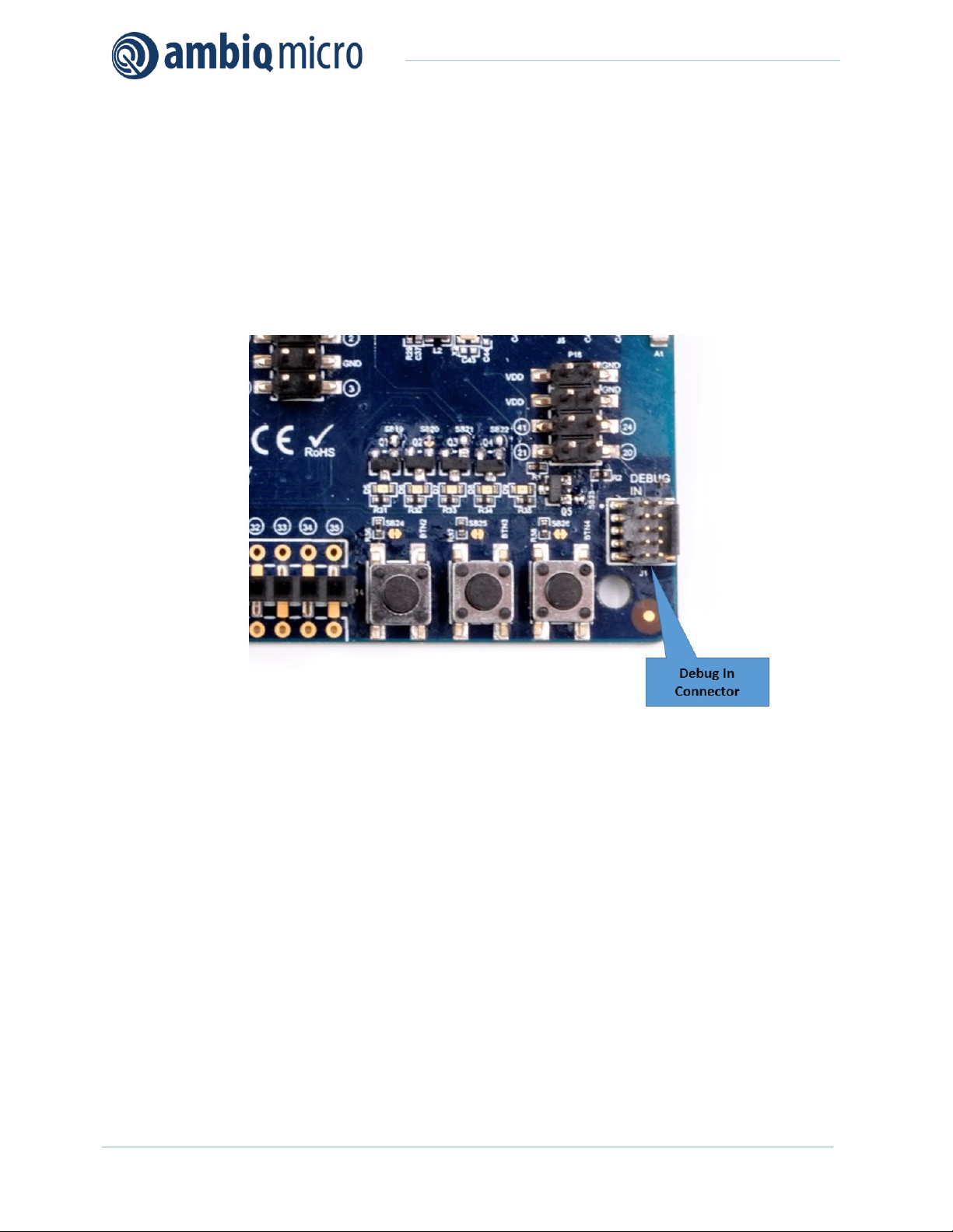
▪ Debugger-in port
▪ Debugger-out port with connection-indication LED
▪ Five user-controlled LEDs
▪ Three push buttons for application use, plus a reset push button
▪ Power slide switch with LED power indicator
▪ Five 8-12 pin Arduino-style headers for pin/power access to shield board(s)
▪ Multiple test points for power measurements
▪ CE Mark and RoHS compliant
Caution: The EVB has components loaded on the back of the board. Care should be taken to not damage
these components. Rubber feet have been applied to the bottom of the board to prevent direct contact
between the components and a desk surface.
3.1 Secure Boot on the Apollo3 Blue Plus MCU
Apollo3 Blue Plus MCU parts from the Ambiq Micro factory are preprogrammed with a Secure Bootloader
and an uninitialized Customer InfoSpace, referred to as INFO0. Initial provisioning of the part would include
programming a valid INFO0 and programming the main firmware image in the flash. The Apollo3 Blue Plus
EVB is shipped with the INFO0 configuration preprogrammed with optimal settings for the EVB layout.
For your reference, the following settings are programmed into INFO0 on the Apollo3 Blue Plus MCU
resident on the EVB:
▪ Simo Buck is enabled, which provides lowest Apollo3 Plus power consumption in both active and sleep
modes.
▪ Secure Bootloader (SBL) interface is configured to UART using GPIO22 and GPIO23, which allows
secure boot to be performed over the J-Link COM interface of the EVB.
▪ SBL override pin is configured to GPIO16 which is BTN1 on the EVB.
▪ All Flash and Debugger protection features are disabled.
For information on changing the INFO0 settings as well as using the Secure Bootloader, please refer to the
Apollo3 Blue Getting Started Guide, which can be found in the Ambiq Micro SDK documentation and
example scripts located in the \tools\apollo3_blue_scripts folder. This folder contains a number of python
scripts to demonstrate generation of INFO0 settings, customer main images, and the creation of images
for the Wired Update protocol over UART.

Apollo3 Blue Plus EVB Quick Start Guide
Ultra-Low Power Apollo MCU Family
QS_A3P_1p1 Page 8 2020 Ambiq Micro, Inc.
All rights reserved.
4. Debug Interface
The debug interface is supported by standard J-Link drivers from Segger. Please refer to “Software
Development Tools” on page 10 for more details on J-Link debug support.
4.1 Use of External Debugger
This EVB also supports the use of an external Cortex SWD debug interface through a standard 10-pin
debug header (DEBUG IN - J1) as shown in Figure 3.
Figure 3. Apollo3 Blue Plus EVB’s Cortex DEBUG IN Header (J1)
No jumper changes are required to use an external debug adapter. Simply connect the external debug
adapter with a 10-pin ribbon cable connector to the “DEBUG IN” header.
4.2 Use of J-Link Adapter as an External Target Board Debugger
The EVB also offers the ability to be used as a J-Link debug adapter for any target board that has an
Apollo family MCU.

Apollo3 Blue Plus EVB Quick Start Guide
Ultra-Low Power Apollo MCU Family
QS_A3P_1p1 Page 9 2020 Ambiq Micro, Inc.
All rights reserved.
Figure 4. Apollo3 Blue Plus EVB’s DEBUG OUT Header (J2)
To utilize this functionality, use a 10-pin low-pitch standard debug connector to connect the “DEBUG OUT”
header (J2) on the EVB to the debug header on the target board. The EVB will automatically detect when
the “DEBUG OUT” header is connected to another target board and reconfigure the integrated J-Link to
connect to this external board rather than the on-board Apollo3 Blue Plus.
Note: A voltage on pin 1 of the J2 header is required for the above mentioned automatic switch to occur.
Also, if the target VDD doesn't match the on-board voltage (either 3.3V or 1.8V), and to avoid possible
voltage level conflicts on the debug I/O port, VDDIO of the J-Link processor may need to be changed to the
target voltage by cutting SB5 and shorting SB6.
An LED (D3) is on the board to indicate the presence of VDD_EXT_DBG on pin1 of the J2 header. When
D3 is ON, the debugger is debugging external target board. When D3 is OFF, the debugger is debugging
the on-board Apollo3 Blue Plus MCU.
Figure 5. Apollo3 Blue Plus EVB’s DEBUG OUT LED (D3)

Apollo3 Blue Plus EVB Quick Start Guide
Ultra-Low Power Apollo MCU Family
QS_A3P_1p1 Page 10 2020 Ambiq Micro, Inc.
All rights reserved.
5. Software Development Tools
The standard Segger J-Link debug interface is used on the Apollo3 Blue Plus EVB. Please install the latest
Segger J-Link software, and configure your preferred development IDE (Keil, IAR, or Eclipse) to use J-Link
debug interface.
Links to development tools that support Apollo3 Blue Plus:
▪SEGGER J-Link Software (6.48b Beta or later): https://www.segger.com/downloads/jlink
▪ KEIL uVision 5 (MDK5.25 or later): https://www.keil.com/demo/eval/arm.htm
▪ New Keil Pack (Also used by Eclipse): http://www.keil.com/dd2/pack/#/third-party-download-dialog
▪ IAR Version (8.10.1 or later): https://www.iar.com/iar-embedded-workbench/tools-for-arm/arm-cortex-m-
edition/
▪ GCC 5.3.1: https://gcc.gnu.org
Regardless of preferred IDE, please install the Segger J-Link software. All of the above development
environments support J-Link, but you must have the latest J-Link software installed. Most alternate
development environments also are supported by J-Link.
Please refer to the AmbiqSuite Getting Started Guide (AMSDKGS) at https://ambiqmicro.com/wp-content/
uploads/2017/09/AMSDKGS-v1_1.pdf for more details on setting up development IDEs to use J-Link.

Apollo3 Blue Plus EVB Quick Start Guide
Ultra-Low Power Apollo MCU Family
QS_A3P_1p1 Page 11 2020 Ambiq Micro, Inc.
All rights reserved.
6. Power Supply Options and Measuring Current
There are three power supply options for the Apollo3 Blue PlusEVB:
▪ Operate at 3.3V as provided by the on-board power supply
▪ Operate at 1.8V as provided by the on-board power supply
▪ Provide externally supplied power
Figure 6 shows header P19 which is used to select a power configuration through jumper installations, as
well as the option to measure the supply current to the MCU with an ammeter. Solder bridge SB15 can be
filled instead of jumpering from pin 1 to pin 2 if current measuring is of no interest.
Figure 6. Voltage Selection on Header P19
Table 2 shows valid jumper configurations for P19. All other configurations are invalid. Note that a jumper
across pins 7 and 8 is not necessary and does not do anything - the pins are available only for easy access
to ground.
Table 2: Jumper Configuration for Power Selections
Jumper
1-2
Jumper
3-4
Jumper
5-6 Power Source
In In Out 3.3V operation from internal regulator
In In In 1.8V operation from internal regulator
Out In Out Intended for current measuring across pins 1 and 2
during 3.3V operation from internal regulator
Out In In Intended for current measuring across pins 1 and 2
during 1.8V operation from internal regulator
In Out Out Externally-provided supply voltage within the allowable
range (1.755-3.60V) on pin 3 or 5
Out Out Out
Intended for current measuring across pins 1 and 2
during externally-provided supply voltage within the
allowable range (1.755-3.60V) on pin 3 or 5
_1.8V

Apollo3 Blue Plus EVB Quick Start Guide
Ultra-Low Power Apollo MCU Family
QS_A3P_1p1 Page 12 2020 Ambiq Micro, Inc.
All rights reserved.
As an example for setting the jumpers on P19, Figure 7 shows the EVB configured for 3.3V operation with
jumper across VDD_PS and VDD_MCU for no current measurement.
Figure 7. Header P19 Configured for 3.3V Operation - No Current Measurement
Figure 8 shows the EVB configured for 3.3V operation with current measuring leads across VDD_PS and
VDD_MCU for current measurement.
Figure 8. Header P19 Configured for 3.3V Operation - With Current Measurement
Measuring the current consumption of the target MCU on the board using equipment with a sensing
resistor will create a burden voltage over the resistor on VDD_MCU. In some cases the burden voltage
may be too high and may cause a brown-out event on the target MCU at 1.8V. SB1 on the board can be

Apollo3 Blue Plus EVB Quick Start Guide
Ultra-Low Power Apollo MCU Family
QS_A3P_1p1 Page 13 2020 Ambiq Micro, Inc.
All rights reserved.
cut to make U8 (VDD_PS_LDO generator) output 1.9V instead of 1.8V in the low-voltage configuration.
This will enable current consumption measuring using equipment with a sensing resistor, such as a digital
multimeter.
Figure 9. Solder Bridge SB1

Apollo3 Blue Plus EVB Quick Start Guide
Ultra-Low Power Apollo MCU Family
QS_A3P_1p1 Page 14 2020 Ambiq Micro, Inc.
All rights reserved.
7. FTDI Interface
The on-board FTDI chip (FT4222H) is a SPI to USB data streaming interface from the Apollo3 Blue Plus to
the connected PC. Transfer speed can exceed 200KBytes/sec, and the user can send generic data and
audio data to the PC over the interface at same time. Audio data is supported in raw PCM (16bit/16Khz),
SPP and OPUS formats. Complete instructions for using the interface with provided software can be found
in an article in the Ambiq Micro Support Community Knowledge Base -
https://support.ambiqmicro.com/hc/en-us/articles/360037829251.

Apollo3 Blue Plus EVB Quick Start Guide
Ultra-Low Power Apollo MCU Family
QS_A3P_1p1 Page 15 2020 Ambiq Micro, Inc.
All rights reserved.
Contact Information
Address Ambiq Micro, Inc.
6500 River Place Blvd.
Building 7, Suite 200
Austin, TX 78730-1156
Phone +1 (512) 879-2850
Website https://ambiqmicro.com/
Sales [email protected]
Technical Support https://support.ambiqmicro.com
Legal Information and Disclaimers
AMBIQ MICRO INTENDS FOR THE CONTENT CONTAINED IN THE DOCUMENT TO BE ACCURATE AND RELIABLE. THIS CONTENT MAY, HOW-
EVER, CONTAIN TECHNICAL INACCURACIES, TYPOGRAPHICAL ERRORS OR OTHER MISTAKES. AMBIQ MICRO MAY MAKE CORRECTIONS
OR OTHER CHANGES TO THIS CONTENT AT ANY TIME. AMBIQ MICRO AND ITS SUPPLIERS RESERVE THE RIGHT TO MAKE CORRECTIONS,
MODIFICATIONS, ENHANCEMENTS, IMPROVEMENTS AND OTHER CHANGES TO ITS PRODUCTS, PROGRAMS AND SERVICES AT ANY TIME
OR TO DISCONTINUE ANY PRODUCTS, PROGRAMS, OR SERVICES WITHOUT NOTICE.
THE CONTENT IN THIS DOCUMENT IS PROVIDED "AS IS". AMBIQ MICRO AND ITS RESPECTIVE SUPPLIERS MAKE NO REPRESENTATIONS
ABOUT THE SUITABILITY OF THIS CONTENT FOR ANY PURPOSE AND DISCLAIM ALL WARRANTIES AND CONDITIONS WITH REGARD TO
THIS CONTENT, INCLUDING BUT NOT LIMITED TO, ALL IMPLIED WARRANTIES AND CONDITIONS OF MERCHANTABILITY, FITNESS FOR A
PARTICULAR PURPOSE, TITLE AND NON-INFRINGEMENT OF ANY THIRD PARTY INTELLECTUAL PROPERTY RIGHT.
AMBIQ MICRO DOES NOT WARRANT OR REPRESENT THAT ANY LICENSE, EITHER EXPRESS OR IMPLIED, IS GRANTED UNDER ANY PAT-
ENT RIGHT, COPYRIGHT, MASK WORK RIGHT, OR OTHER INTELLECTUAL PROPERTY RIGHT OF AMBIQ MICRO COVERING OR RELATING TO
THIS CONTENT OR ANY COMBINATION, MACHINE, OR PROCESS TO WHICH THIS CONTENT RELATE OR WITH WHICH THIS CONTENT MAY
BE USED.
USE OF THE INFORMATION IN THIS DOCUMENT MAY REQUIRE A LICENSE FROM A THIRD PARTY UNDER THE PATENTS OR OTHER INTEL-
LECTUAL PROPERTY OF THAT THIRD PARTY, OR A LICENSE FROM AMBIQ MICRO UNDER THE PATENTS OR OTHER INTELLECTUAL PROP-
ERTY OF AMBIQ MICRO.
INFORMATION IN THIS DOCUMENT IS PROVIDED SOLELY TO ENABLE SYSTEM AND SOFTWARE IMPLEMENTERS TO USE AMBIQ MICRO
PRODUCTS. THERE ARE NO EXPRESS OR IMPLIED COPYRIGHT LICENSES GRANTED HEREUNDER TO DESIGN OR FABRICATE ANY INTE-
GRATED CIRCUITS OR INTEGRATED CIRCUITS BASED ON THE INFORMATION IN THIS DOCUMENT. AMBIQ MICRO RESERVES THE RIGHT
TO MAKE CHANGES WITHOUT FURTHER NOTICE TO ANY PRODUCTS HEREIN. AMBIQ MICRO MAKES NO WARRANTY, REPRESENTATION
OR GUARANTEE REGARDING THE SUITABILITY OF ITS PRODUCTS FOR ANY PARTICULAR PURPOSE, NOR DOES AMBIQ MICRO ASSUME
ANY LIABILITY ARISING OUT OF THE APPLICATION OR USE OF ANY PRODUCT OR CIRCUIT, AND SPECIFICALLY DISCLAIMS ANY AND ALL
LIABILITY, INCLUDING WITHOUT LIMITATION CONSEQUENTIAL OR INCIDENTAL DAMAGES. “TYPICAL” PARAMETERS WHICH MAY BE PRO-
VIDED IN AMBIQ MICRO DATA SHEETS AND/OR SPECIFICATIONS CAN AND DO VARY IN DIFFERENT APPLICATIONS AND ACTUAL PERFOR-
MANCE MAY VARY OVER TIME. ALL OPERATING PARAMETERS, INCLUDING “TYPICALS” MUST BE VALIDATED FOR EACH CUSTOMER
APPLICATION BY CUSTOMER’S TECHNICAL EXPERTS. AMBIQ MICRO DOES NOT CONVEY ANY LICENSE UNDER NEITHER ITS PATENT
RIGHTS NOR THE RIGHTS OF OTHERS. AMBIQ MICRO PRODUCTS ARE NOT DESIGNED, INTENDED, OR AUTHORIZED FOR USE AS COMPO-
NENTS IN SYSTEMS INTENDED FOR SURGICAL IMPLANT INTO THE BODY, OR OTHER APPLICATIONS INTENDED TO SUPPORT OR SUSTAIN
LIFE, OR FOR ANY OTHER APPLICATION IN WHICH THE FAILURE OF THE AMBIQ MICRO PRODUCT COULD CREATE A SITUATION WHERE
PERSONAL INJURY OR DEATH MAY OCCUR. SHOULD BUYER PURCHASE OR USE AMBIQ MICRO PRODUCTS FOR ANY SUCH UNINTENDED
OR UNAUTHORIZED APPLICATION, BUYER SHALL INDEMNIFY AND HOLD AMBIQ MICRO AND ITS OFFICERS, EMPLOYEES, SUBSIDIARIES,
AFFILIATES, AND DISTRIBUTORS HARMLESS AGAINST ALL CLAIMS, COSTS, DAMAGES, AND EXPENSES, AND REASONABLE ATTORNEY
FEES ARISING OUT OF, DIRECTLY OR INDIRECTLY, ANY CLAIM OF PERSONAL INJURY OR DEATH ASSOCIATED WITH SUCH UNINTENDED
OR UNAUTHORIZED USE, EVEN IF SUCH CLAIM ALLEGES THAT AMBIQ MICRO WAS NEGLIGENT REGARDING THE DESIGN OR MANUFAC-
TURE OF THE PART.
Table of contents
Other ambiq micro Motherboard manuals
Popular Motherboard manuals by other brands

NXP Semiconductors
NXP Semiconductors FRDM-HB2000-EVM user guide

AOpen
AOpen AX45 PRO-533 Easy installation guide

Intel
Intel BLKDP67BG Technical product specification

EVGA
EVGA P67 FTW Specifications

Supermicro
Supermicro C7B250-CB-ML Quick reference guide

Arbor Technology
Arbor Technology ITX-i67M0 Quick installation guide