Ameba DVR-R216 User manual

- 1 -
16CH Digital Video Recorder
Thank you for purchasing our product. Please read this Users Manual before using the product.
16 Channel Digital Video Recorder
V.1.0

- 2 -
SAFETY PRECAUTIONS
CAUTION
RISK OF ELECTRIC
SHOCK. DO NOT OPEN!
CAUTION : TO REDUCE THE RISK OF ELECTRICAL SHOCK, DO NOT OPEN COVERS.
NO USER SERVICEABLE PARTS INSIDE. REFER SERVICING TO QUALIFIED
SERVICE PERSONNEL.
This label may appear on the bottom of the unit due to space limitations.
The lightning flash with an arrowhead symbol within an equilateral triangle is intended
to alert the user to the presence of uninsulated “ dangerous voltage” within the
product’s enclosure that may be of sufficient magnitude to constitute a risk of electric
shock to persons.
The exclamation point within an equilateral triangle is intended to alert the user to
presence of important operating and maintenance (Servicing) instructions in the
literature accompanying the appliance.
WARNING : TO PREVENT FIRE OR SHOCK HAZARD, DO NOT EXPOSE UNITS NOT
SPECIFICALLY DESIGNED FOR OUTDOOR USE TO RAIN OR MOISTURE.
Attention: installation should be performed by qualified service Personnel only in
accordance with the National Electrical Code or applicable local codes.
Power Disconnect. Units with or without ON-OFF switches have power supplied to
the unit whenever the power cord is inserted into the power source ; however, the unit
is operational only when the ON-OFF switch is in the ON position. The power cord is
the main power disconnect for all unites.

- 3 -
Contents
1BEFORE READING THIS DOCUMENT .............................................................5
2UNIT DESCRIPTION..............................................................................................6
2.1FRONT PANEL .....................................................................................................................................6
2.2REAR PANEL .......................................................................................................................................7
2.3CONTROLLER......................................................................................................................................8
3INSTALLATION ......................................................................................................9
3.1CAMERA CONNECTION ....................................................................................................................9
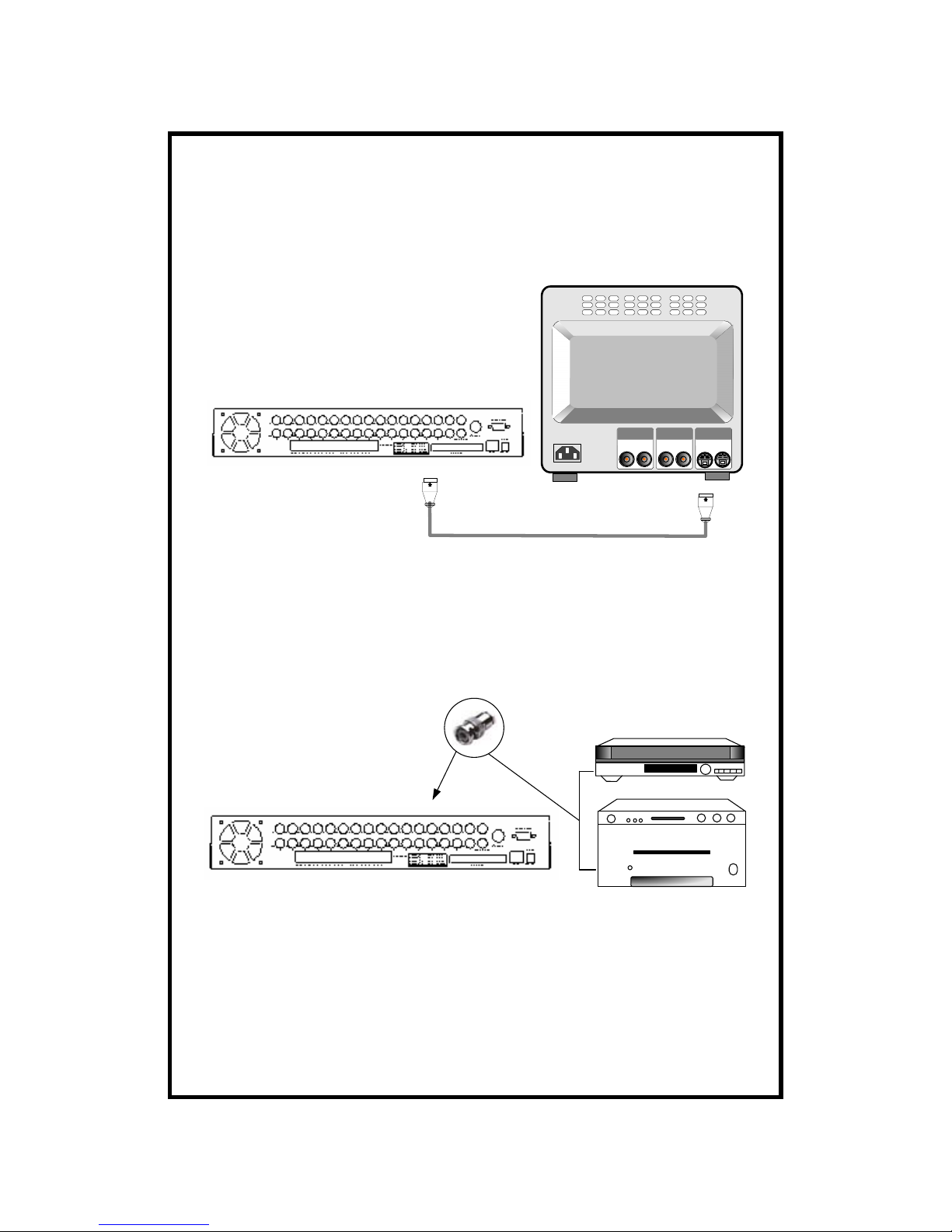
3.2MONITOR CONNECTION (COMPOSITE MONITOR).....................................................................9
3.3MONITOR (S-VHS) CONNECTION..............................................................................................10
3.4VCR&VIDEO PRINTER CONNECTION.................................................................................10
3.5NETWORK CONNECTION................................................................................................................11
3.6HDD CONNECTION.........................................................................................................................12
3.7POWER CONNECTION......................................................................................................................13
4OPERATION...........................................................................................................14
4.1BASIC DISPLAY.................................................................................................................................14
4.2DVR SYSTEM LOG-IN ................................................................................................................16
4.3RECORDING.......................................................................................................................................17
4.4PLAYBACK.........................................................................................................................................20
5SETUP......................................................................................................................24
5.1BASIC OPERATION ...........................................................................................................................24
5.2CAMERA SETUP .........................................................................................................................25
5.3ADJUST COLOR ..........................................................................................................................26
5.4MOTION SETUP ..........................................................................................................................27
5.5SET TIME/DATE...........................................................................................................................29
5.6REC SETUP ....................................................................................................................................30
5.7HDD MANAGEMENT ...............................................................................................................32
5.8MISCELLANEOUS SETUP .....................................................................................................33
6HDD BOX ................................................................................................................39
7SPECIFICATION AND CONFIGURATION ......................................................40

- 4 -
Remote Viewer Software
MANUAL FOR REMOTE VIEWER SOFTWARE ..............................................44
1.GENERAL DESCRIPTION.................................................................................................................44
2.TCP/IP SETUP IN DVR UNIT.....................................................................................................44
3.STATIC IPAND DYNAMIC IP.........................................................................................................45
4.LIVE VIEW VIA IP NETWORK........................................................................................................47
5.SEARCH RECORDED PICTURES VIA IP NETWORK .................................................................51

- 5 -
1Before reading this document
(1) This document is intended for both the administrator and users of stand
alone DVR Model.
(2) This manual contains information for configuring, managing and using
stand alone DVR Model.
(3) To prevent fire or electrical shock, do not expose the product to heat or
moisture
(4) Be sure to read this manual before using stand alone DVR Model.
(5) For questions and technical assistance of this product, contact your local
dealer.
recommendation on installation of the DVR unit
(1) Check electricity at the place you want to install the DVR unit is stable
and meets our electricity requirements. Unstable electricity will cause
malfunction of the unit or give critical damage to the unit.
(2) Several chips on the main board of the DVR unit and hard disk drive
inside the unit generate heat, and it must be properly discharged. Do not
put any objects just beside exhaust port(fan) on the left side of the unit and
do not close up an opening (fresh air in-take) on the right side of the unit.
(3) Put the DVR unit at well-ventilated place and do not put heat-generating
objects on the unit. When it is installed inside 15 inch mounting rack
together with other devices, please check built-in ventilation fan of the
rack is properly running.

- 6 -
2Unit Description
2.1 Front Panel
10 11121314 15 16
1 2 3 4 5 67 8 9
1. LED (overwrite/Rec/Play/Setup)
2. 1~16CH Camera
3. REC:REC image data on hard disk drive
4. STOP: stop Recording or playback
5. REW: High speed playback in reverse direction in playback mode, or moving to
the start of Record data when it is in stop mode.
6. PLAY: Play-Back
7. FF: High speed playback in forward direction in playback mode, or moving to the
last of Record data when it is in stop mode.
8. PAUSE: pauses when it is in playback mode
9. ENTER: Used as selection key in system setup or changes contents displayed in
live display.
10. MODE: MODE represents multi-screen division and used to change to
4-split,9-split,16-split screen.
11.FRZ:On-off switch to freeze pictures in live mode
12SEQ: In full screen, this button shows pictures in rotation.
13.ZOOM:In full screen ,this button enlarges pictures two times
14.PIP: In full screen, this button creates PIP in rotation
15.P/T: Enter into or exit from PAN/TITL control mode.
16.MENU: used to change menu in system setup.

- 7 -
2.2 Rear Panel
nopqrstu v
nFAN
oALARM INPUT/OUPUT
1 ALARM 1 13 ALARM 11
2 ALARM 2 14 ALARM 12
3 ALARM 3 15 GND
4 ALARM 4 16 ALARM 13
5 GND 17 ALARM 14
6 ALARM 5 18 ALARM 15
7 ALARM 6 19 ALARM 16
8 ALARM 7 20 GND
9 ALARM 8 21 RELAY OUT-N.O.
10 GND 22 RELAY OUT-N.C.
11 ALARM 9 23 RELAY OUT-COM
12 ALARM 10
pCAMERA CONNECTION
qVIDEO OUT
rHDD BOX
sS-VIDEO
tRJ-45
uRS-232
vDC POWER

- 8 -
2.3 Controller
1REC:REC image data on hard disk drive
2STOP: stop REC or playback
3REW: High speed playback in reverse direction in playback mode, or
moving to the start of REC data when it is in stop mode.
4PLAY: Play-Back
5FF: High speed playback in forward direction in playback mode, or moving to
the last of REC data when it is in stop mode.
6PAUSE: pauses when it is in playback mode
7ENTER: Used as selection key in system setup or changes contents displayed in
live display.
8MODE: MODE represents multi-screen division and used to change to
4-split,9-split,16-split screen.
9FRZ: On-off switch to freeze pictures in live mode
10 SEQ: In full screen, this button shows pictures in rotation.
11 ZOOM: In full screen ,this button enlarges pictures two times
12 PIP: In full screen, this button creates PIP in rotation
13 P/T: Enter into or exit from PAN/TITL control mode.
14 MENU: used to change menu in system setup.

- 9 -
3Installation
3.1 Camera Connection
Connect camera to the CAMERA INPUT(1~16)on the rear panel of unit.
3.2 Monitor Connection (Composite monitor)
Connect the monitor to the MONITOR OUT on the rear panel of unit.

- 10 -
3.3 Monitor (S-VHS) Connection
Connect S-VIDEO monitor to MONITOR OUT(S-VHS)on the rear panel of unit.
3.4 VCR&VIDEO PRINTER Connection
Connect VCR or Video printer to VCR OUT on the rear panel of unit.

- 11 -
3.5 Network connection
RS-232C:Connected to PC to operate with key board
RS-485:Connected to P/T Controller or Speed Dome Camera
RJ-45:Connected to LAN,WAN or internet.
Notice: Teratray connection port must be used for connecting HDD Bay and
can not be used for connecting other device. Connection must be done while
p
ower supply to DVR unit is cut.

- 12 -
3.6 HDD Connection
Connect main board and HDD using IDE HDD cable and power cable included
in the package. If you install just a unit of HDD, jumper setting of HDD MUST
BE ON mater, as specified by HDD manufacturer , and you can install it at any
location of HDD1 or HDD2.
In case you install 2HDD, HDD1 must be master and HDD2 is slave, and jumper
setting must be done properly as specified by HDD manufacturer.
Fix HDD on the bottom of DVR case using screws included in the package.
Screws must be inserted from outside of the bottom.
Notice: Formatting before installation is not required, because DVR system
automatically detects HDD and formats. In the first operation after installation of
HDD, first clear all data on HDD and set at FACTORY DEFAULT in SETUP
menu of DVR system.

- 13 -
3.7 Power connection
Connect DC 12V power to the power connection on the rear panel of DVR unit.
DC 12V
~Selection of video system(NTSC/PJAL system)
You can set video system in the process of booing. according to video system of
camera, set video system as follows.
~NTSC system: While you press MENU button and LEFT button at the same
time, turn DC power switch on. Press two buttons until you hear beep sound from
DVR unit.
~PAL system: While you press MENU button and RIGHT button at the same
time,turn DC power switch on. Press two buttons until you hear beep sound from
DVR unit.
From next booting, it is not necessary to set as above .DVR system memorize video
setting. In the process of booting, DVR system displays ”VIDEO SYSTEM
SETTING TO NTSC(OR PAL)” on bottom of screen to inform you video system
you selected.
~Turn on the power and log on the system
Follow direction of log-in part of this manual to input own password and start the
system. Just press enter button if you do not want to input own password.
~Detail setup in system setup
Refer to system setup of this manual
Notice: To connect HDD Bay to DVR unit, first turn off power to both DVR unit and
HDD Bay. then turn on power to HDD bay first and then DVR unit after more than
5 seconds.

- 14 -
4Operation
4.1 Basic display
Turn on the power switch, and DVR system shows live display from 1 to 16 as
following figure. DVR system already started to REC picture data automatically.

- 15 -
(1).First operation
After power supply, DVR system automatically starts to REC on Timer
Recording mode.
A. If press PLAYBACK button shortly, playback starts from last stop
point. If
Press PLAYBACK button once more in playback mode, direction of
Playback is reversed. if press PLAYBACK button in long time while
DVR system is in stop mode, you can enter into go to menu. for details,
refer to playback part of this manual.
B. If press FF button in playback mode,(1X)is displayed, and you can
select speed of playback higher thanx1.If press FF button repeatedly,
speed of playback is increased from 1,2,4,8,16,32,UP to 64.To the
contrary, if press REW button in playback in x1 speed, playback speed
is decreased to 1/2 and then 1/4.
C. To go back to menu, press MENU button while in stop mode.
(2).Set time when you first operate DVR unit.
Refer to time/data setup in system setup in this manual.
(3).To enter into 4-spjlit,9-sjplit screen during live monitoring or playback, press
MODE button first and then 1,2 or 3 respectively.
(4).Display of camera channel
In 16-split screen, camera title is shown in numbers by the system from 1 to
16 and in 4-split and 9-split screen, camera title set y user is shown.
(5).Shows how much space in HDD is Record
A. REC indicates percentage of HDD space used until now.
B. Play indicates starting point from which next playback will start. it is the
point where last playback stopped. To start playback from the first of
Recording ,press REW button to set play at 0.00% and then press
playback button. To replay reverse direction from the end of
Recording ,press FF button to move to the end of Recording, and then
press playback button.

- 16 -
4.2 DVR SYSTEM Log-in
(1)After system starts to operate, press MENU button to enter into system
menu.
(2)Login DVR system is displayed as shown on the left.
(3)If you want to input for your own password, just press ENTER button.
(4)Then press ENTER button.
~If password you entered is consistent with password already set, ”PASSWORD
OK” is displayed, and you enter into system setup. if it is not, system goes back to
live display mode.
~Factory default password is ENTER
~We recommend users to set own password in the first operation. For details refer to
password setup in system setup-miscellaneous setup.
~Be careful to memorize own password to operate DVR unit properly.

- 17 -
4.3 Recording
(1)Basic Recording method
Press REC button, then Recording icon is displayed on the top of screen. If
DVR system is booted again, it is not necessary to set Recording settings,
because Recording setting remains unchanged and memorized.
(2)FRZ
Ifpress FRZ BUTTON,”FRZ” is displayed on top left.
Then press number of channel you want to freeze. Picture of channel you
selected is freeze. picture of channel you selected freeze, and (F)icon is
displayed on the left of camera title. Press FRZ button again to exit.
(3)SEQ
Ifpress SEQ button in live display when it is in full screen of any channel,
it shows full screen pictures in rotation.
Rotation time interval can be set in system setup-miscellaneous setup-timer
setup.

- 18 -
(4)ZOOM
Ifpress ZOOM button in full screen of one of 16 channel, system enlarges
this picture two times. using direction keys on the left of front panel, you can
select area to be enlarged.
(5)PIP
While you see picture of specific channel in full screen, you can see small size
pictures of remaining channels in rotation, if you pres PIP button. Time
interval of PIP can be set in system setup-miscellaneous-timer setup.
If press SEQ button while it is in PIP mode, picture in full screen and PIP
are all rotate.

- 19 -
(6)P/T
You can connect PTZ camera or speed dome camera to DVR unit, and you
must input protocol of camera to control camera while you see live pictures,
using buttons on the front of DVR unit or remote controller.
A. Basic control button: Enter-transmit command while pressed
UP/DOWN-Selection of menu item
B. LEFT/RIGHT-Select command
Fordetails,refertosystem setup-miscellaneous-PAN/TITL CMD setup.
Operation:1.Press P/T BUTTON.
2.Selectdeviceusing buttons.
3.Selectcommandusing button to exit.
~Maximum numbers of PTZ camera can be connected to DVR unit is 4.
(7)REC setting
A. Timer Recording: Recording by time
Example: REC all images at set Recording rate and overwrite when HDD
is full.
1. Log-in to system setup.
2. Move to REC setup item and enter.
3. Using direction keys as figure-b

- 20 -
B. Motion Recording: Recording when motion is detected.
Example: Just REC for 30 seconds whenever motion is detected, and stop
Recording when HDD is full.
Log-in to system setup
Mover to REC setup and enter.
Using direction keys, ser as figure-b
C. Alarm Recording: Recording when alarm is activated very similar to
motion
Recording.
(8)Cautions
A. When you are in system setup, Recording is stopped.
B. While DVR system is in playback mode, Recording is stopped.
C. No Recording is done in channel to which you did not connect camera.
4.4 Playback
(1)Basic operation
A. If press PLAYBACK button shortly, DVR system starts to replay.
B. If press PLAYBACK button once again, direction of playback is
reversed.
C. If press PLAYBACK button in long time when DVR system is in
stop mode, you can enter go to menu.
Table of contents
Other Ameba DVR manuals
Popular DVR manuals by other brands

Q-See
Q-See QSD2316L Quick installation guide

HIK VISION
HIK VISION DS-8000HSI-S Series Technical manual

ICRealtime
ICRealtime Mobile DVR Installation instruction guide

HIK VISION
HIK VISION DS-7300HI-S Series quick start guide

HIK VISION
HIK VISION DS-8104HMI-B Series Technical manual

HIK VISION
HIK VISION DS-72 Series Installation guide and quick start guide