Ameba R204 User manual

Digital Video Recorder
4 Channel Digital Video Recorder
V1.1
1

SAFETY PRECAUTIONS
CAUTION
RISK OF ELECTRIC
SHOCK. DO NOT OPEN!
CAUTION : TO REDUCE THE RISK OF ELECTRICAL SHOCK, DO NOT OPEN COVERS.
NO USER SERVICEABLE PARTS INSIDE. REFER SERVICING TO QUALIFIED
SERVICE PERSONNEL.
This label may appear on the bottom of the unit due to space limitations.
The lightning flash with an arrowhead symbol within an equilateral triangle is intended
to alert the user to the presence of uninsulated ?dangerous voltage?within the
product enclosure that may be of sufficient magnitude to constitute a risk of electric
shock to persons.
The exclamation point within an equilateral triangle is intended to alert the user to
presence of important operating and maintenance (Servicing) instructions in the
literature accompanying the appliance.
WARNING : TO PREVENT FIRE OR SHOCK HAZARD, DO NOT EXPOSE UNITS NOT
SPECIFICALLY DESIGNED FOR OUTDOOR USE TO RAIN OR MOISTURE.
Attention: installation should be performed by qualified service Personnel only in
accordance with the National Electrical Code or applicable local codes.
Power Disconnect. Units with or without ON-OFF switches have power supplied to
the unit whenever the power cord is inserted into the power source ; however, the unit
is operational only when the ON-OFF switch is in the ON position. The power cord is
the main power disconnect for all unites.
- 2 -

1.Before reading this document...............................................................5
2.Unit Description.....................................................................................6
2.1Front Panel........................................................................................................6
2.2Rear Panel.........................................................................................................7
2.3Controller..........................................................................................................8
3.Installation..............................................................................................9
3.1Camera Connection...........................................................................................9
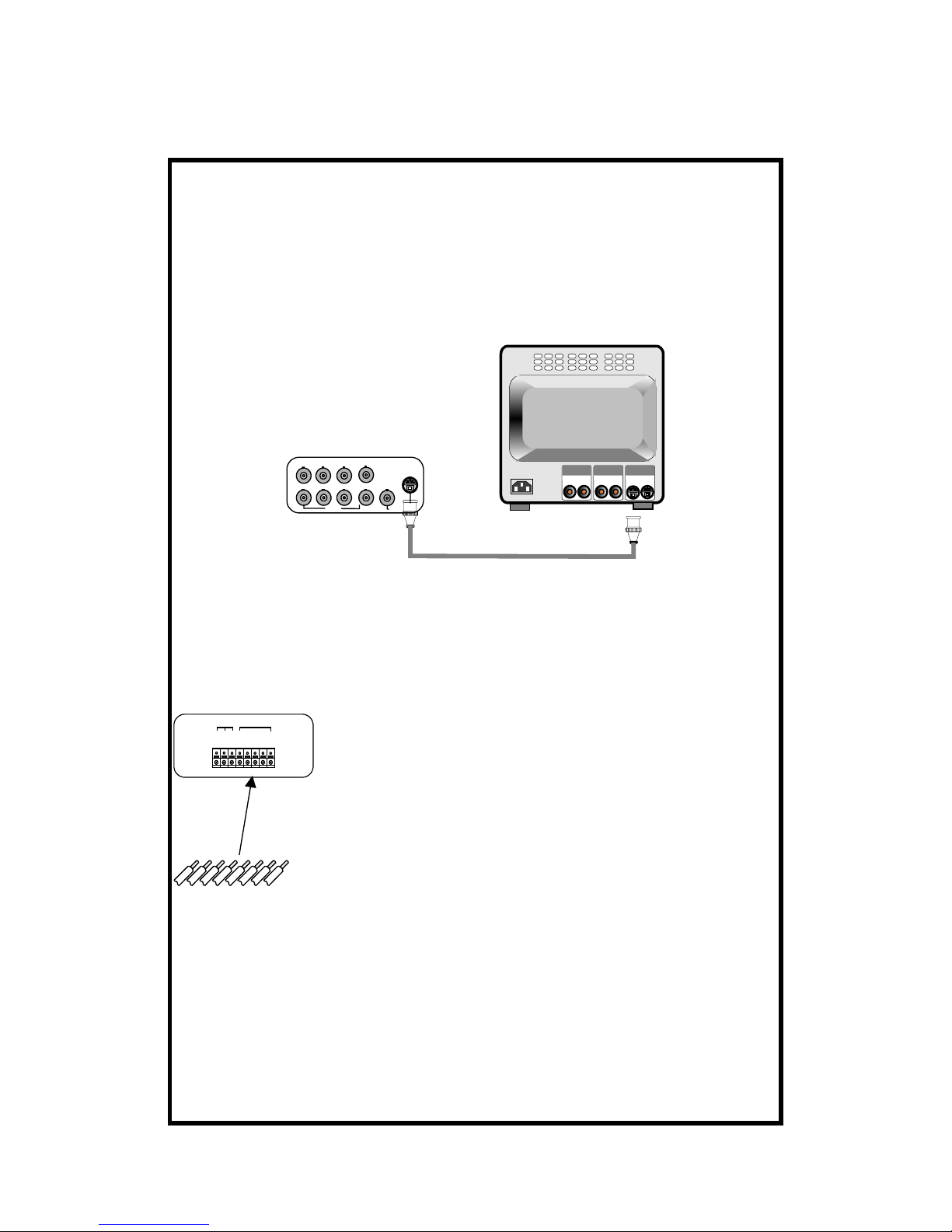
3.2Monitor Connection (Composite monitor) .......................................................9
3.3Monitor (S-VHS) Connection.........................................................................10
3.4VCR&VIDEO PRINTER Connection............................................................10
3.5Network connection........................................................................................11
3.6HDD Connection ............................................................................................11
3.7Power connection............................................................................................12
4.Operation..............................................................................................13
4.1LOG-IN...........................................................................................................13
4.2Record.............................................................................................................14
4.3Play .................................................................................................................18
5.SETUP...................................................................................................21
5.1 Basic Operation..............................................................................................21
5.2 DISPLAY SETUP..........................................................................................23
5.3 CAMERA SETUP .........................................................................................24
5.4 TIME/DATE SETUP .....................................................................................26
5.5 ALARM/MOTION SETUP...........................................................................27
5.6 RECORD SETUP..........................................................................................30
5.7 TCP/IP SETUP...............................................................................................31
5.8 MISCELLANEOUS SETUP.........................................................................32
6.HDD BAY..............................................................................................36
6.1 HDD EXTENSION .......................................................................................36
6.2 HDD BAY......................................................................................................36
7.Specification and configuration..........................................................38
- 3 -

Manual for Remote Viewer Software....................................................41
1.General description...........................................................................................41
2.TCP/IP SETUP in DVR unit.............................................................................41
3.Static IP and Dynamic IP..................................................................................41
4.Live view via IP network..................................................................................42
5.Search recorded pictures via IP network...........................................................46
- 4 -

1.Before reading this document
1. This document is intended for both the administrator and users of stand alone
DVR Model.
2. This manual contains information for configuring, managing and using stand
alone DVR Model.
3. To prevent fire or electrical shock, do not expose the product to heat or moisture
4. Be sure to read this manual before using stand alone DVR Model.
5. For questions and technical assistance of this product, contact your local dealer.
※Strong recommendation on installation of the DVR unit
1. Check electricity at the place you want to install the DVR unit is stable and meets
our electricity requirements. Unstable electricity will cause malfunction of the unit
or give critical damage to the unit.
2. Several chips on the main board of the DVR unit and hard disk drive inside the
unit generate heat, and it must be properly discharged. Do not put any objects just
beside exhaust port on the left side of the unit and do not close up an opening on
the right side of the unit.
3. Put the DVR unit at well-ventilated place and do not put heat-generating objects
on the unit. When it is installed inside 15 inch mounting rack together with other
devices, please check built-in ventilation fan of the rack is properly running.
- 5 -

2.Unit Description
2.1Front Panel
12 11
14 12345678910 15 13
※If the Input window is covered, the remote controller may not work
If several buttons are simultaneously or incorrectly pressed, the system may
not function properly.
1.CH1:Camera 1 In Full Screen.
2.CH2:Camera 2 In Full Screen.
3. CH3:Camera 3 In Full Screen.
4. CH4:Camera 4 In Full Screen.
5.QUAD:Changes to quarterly split screen or Full display screen.
6.REC:Video Recode.
7.PIP/MARK:Assigns PIP(Picture in picture)or MARK IMAGE to protect selected
image rom being overwitten.
8.FRZ:Display screen is pause while playback.
9.SPEED/SEQ:The display screen automatically rotates,and playback speed and
direction.
10.ZOO:Enlarges the display screen by 200%
11.PLAY/ENTER:Play-Back
12.MENU:into system SETUP and change item.
13.Dirtection button
14.Lamp
15.Remote Controller Sensor Input window
- 6 -

2.2Rear Panel
12345678
1. RS232 Connection
2. Sensor Input/Output
3.TCP/IP Connect
4. Camera Connection
5.BNC Out
6.S-Video
7.DC Power
8.Fan
※When connecting with other applications, be sure to turn off the system.
- 7 -

2.3Controller
1. 1:Camera 1 In Full Screen.
2. 2:Camera 2 In Full Screen.
3. 3:Camera 3 In Full Screen.
4. 4:Camera 14In Full Screen.
5.QUAD:Changes to quarterly split screen or Full display screen.
6.PIP/MARK:Assigns PIP(Picture in picture)or MARK IMAGE to protect selected
image room being overwritten.
7.FRZ:Display screen is pause while playback.
8.SPEED/SEQ:The display screen automatically rotates, and playback speed and
direction.
9.ZOO:Enlarges the display screen by 200%
10.PLAY/ENTER:Play-Back
11.MENU:into system SETUP and change item.
- 8 -

3.Installation
3.1Camera Connection
Connect the camera to the CAMERA INPUT on the Rear Panel of the system.
CH1 CH2 CH3 CH4
CH1 CH2 CH3 CH4
MONITOR
LOOP
VIDEO
LENS VIDEO
DC
AC24V/DC12
V.P
DC
LEVEL
Rear part of CAMERA
3.2Monitor Connection (Composite monitor)
Connect the monitor to the MONITOR OUT on the Rear Panel of the system
CH1 CH2 CH3 CH4
CH1 CH2 CH3 CH4
MONITOR
LOOP
VIDEO A
IN OUT
VIDEO C
IN OUT
VIDEO B
IN OUT
- 9 -

3.3Monitor (S-VHS) Connection
Connect S-VIDEO Monitor to MONITOR OUT(S-VHS) on the Rear Panel of the
system.
CH1 CH2 CH3 CH4
CH1 CH2 CH3 CH4
MONITOR
LOOP
VIDEO
A
IN OUT
VIDEO
C
IN OUT
VIDEO
B
IN OUT
3.4VCR&VIDEO PRINTER Connection
Connect the Sensor to the SENSOR INPUT/OUTPUT on the Rear Panel of the
system
C
O
M
N
CN
OG
N
D
D
3D
2D
1
D
4
ALARM
RELAY
Terminal block
Pin 1 Alarm1
Pin 2 Alarm2
Pin 3 Alarm3
Pin 4 Alarm4
Pin 5 GND
Pin 6 NO( Normal Open )
Pin 7 NC( Normal Close)
Pin 8 COM
NO
NC
GND
COM
D1
D2
D3
D4
(1)Relay output : COM+NC, COM+NO OR COM+NC+NO
(2)Alarm input : Short-circuit between Alarm1, Alarm2, Alarm3 or Alarm4 and
GND is recognized as alarm.
- 10 -

Internal Circuit
D1
5
V
※Thus, there is a danger of damage, when the sensor input goes to a
Negative level or voltage higher than 5V.
3.5Network connection
Connect LAN
ETHERNET
3.6HDD Connection
Main board
HDD
(Default) HDD
(Option)
(1)Please make it sure to leave HDD cable as folded up small (tied up)
(2)when you connect single HDD to I/O Board of DVR unit, and place port 1 at
connector of I/O Board and connect HDD to port 3 as shown above picture.
(3)When you connect 2 HDD to I/O Board of DVR unit, first unfold HDD cable
and place port 2 at connector of I/O Board, and connect no.1 HDD
(4)Select jump: Second HDD in slave position
- 11 -

3.7Power connection
Connect the power to the POWER CONNECTION on the Rear Panel of the
system, system will work.
DC 12V
.
- 12 -

4.Operation
4.1LOG-IN
1.Press MENU button to enter the system menu after starting the system.
2.LOGIN DVR SYSTEM window appears as shown on the left.
3.Use 1.2.3.4 button to enter password that has 1 to 8 numbers.
4. Use MARK button to change.
5. After entering the password, press MENU button to go back to the system menu.
※If password entered does not match previously set number ※CURENT PW
INPUT ERROR§ message
※Factory default password is as below. The system is equipped with two
passwords.
ADMIN(Administrator): 1
(1)We recommend you to change the password.
(2)Be sure to memorize the changed password.
(3)When logged into USER MODE, only DISPLAY SETUP and TIME/DATE
TYPE SETUP is possible.
- 13 -

4.2Record
1. PLAY
Changes to Playback Mode from Recording.
2. MODE
When MODE button is pressed, the full screen of each channel and
quarterly split screen is played by turns. With 1.2.3.4 button, select full
screen of each camera.
2002 / APR / 01 PM
01:00:00
60FPS REC
CAM1 CAM2
CAM3 CAM4
RecordingBasicScreen
Indicates recording speed
60FPS : 60 Fields/sec
MOTION : records when
motion
is detected
Indicates recording mode
REC : represents recording in
Field Switch Mode
Nothing displayed in Quad
Mode
Indicates recording
conditions
ALARM : records when alarm
condition is
detected
Indicates
camera
channel
3. PIP
(1) Press PIP button.
(2) Use button to choose the ADDRESS of the PIP camera.
(3) Use button to select the command for PIP
(4)With Play/Enter button, select ON/OFF.
(5)Press PIP button to come back to recording screen
- 14 -

2002 / APR / 01 PM 01:00:00
60FPS REC
CAM1 CAM2
CAM3 CAM4
P/T CH1 FOCUS FAR
EXIT : PRESS [P/T]
1.Indicatesaddressofcamera
001~255 2.Select
Command
FOCUS FAR
FOCUS NEAR
FOCUS AUTO
PAN RIGHT
PAN LEFT
TILT UP
TILT DOWN
ZOOM IN
ZOOM OUT
AUTO PAN
LIGHTCMD
WIPER CMD
PUMP CMD
POWER CMD
FUNTION1
FUNTION2
FUNTION3
3. Set ON/OFF
forselected
command
PAN/TILTControlScreen
(Ex:DRX-502Amodel)
4. PICTURE IN PICTURE (PIP)
(1) Use1.2.3.4button to select a camera and set a full screen.
※PIP is not available in quarterly split screen.
(2) Press PIP/MARK button.
(3) With button, select the camera channel in full screen, and with button or
1.2.3.4 button, select the channel of smaller screen.
(4) Press SEQ/SPEED button to make the image in smaller screen rotate.
2002/APR/1 PM09:22:06
60FPS REC PIP FL
PIP WINDOWS MOVE : OFF
MOVE ON/OFF: PRE SS PRZ
CAM1
Indicates if“SEQ” button
selection. Indicates※FRZ §key
selection.
PICTUREINPICTUREScreen
※To change the location of smaller screen, press FRZ button and use
button to move to desired
- 15 -

5. FRZ
(1)Live full screen pauses when FRZ button is pressed.
(2) To pause quarterly split screen, press FRZ button, and with 1.2.3.4button
select channel. On the right of the camera name, message appears and the LIVE
screen of that channel will pause. When pressed once more, it will come back to
LIVE screen.
※When FRZ selected,1.2.3.4button or QUAD button do not work.
To move to full screen of each camera, press FRZ button once more to end
Freeze mode.
CAM1 FRZ CAM2
CAM3 CAM4
2002 / APR / 01 PM 01:00:00
60FPS REC FRZ
Indicates if “FRZ”
buttonselection.
When#1camerais
pausedinQUADscreen
PauseScreen
- 16 -

6.SEQ
(1)In LIVE full screen, press SEQ/SPEED button to make picture from each
channel rotate.
(2) It does not operate in quarterly split screen.
(3) During automatic rotation, press SEQ/SPEED button to stop automatic rotation.
(4) During automatic rotation, press QUAD button to stop automatic rotation and
move to quarterly split screen.
※To change the time interval of the automatic rotation It is possible to select
between 1 second to 99 seconds.
CAM1 CAM2
CAM3 CAM4
2002 / APR / 01 PM 01:00:00
60FPS REC
Quarterly split (Quad) screen
2002 / APR / 01 PM 01:00:00
60FPS REC SEQ
Automaticrotation ofthe FullScreen
AB
CD D
C
B
A
Fullscreen
automatically rotatesby
thevalueof
SEQUENCE
INTERVAL in A/B/C/D/
A/B/C..
7. Sensor Recording
(1) When there is sensor input, the recording starts.
8. Scheduled Recording
Records by date and by day of the week.
9. Recording by MOTION DETECTION
※Recording is stopped during SYSTEM SETUP.
※Recording is stopped during playback, or search in playback mode.
※Recording is not possible if no camera is connected.
- 17 -

4.3Play
1. Playback setup
(1) Press Play/Enter button to begin playback.
(2) Display screen as shown on the right will appear
(3) Press Play/Enter button again to start playback from START picture.
(4) To come back to recording mode. press Play button.
START : 2002/APR/12 AM 07:40:38
END : 2002/APR/20 PM 02:11:56
GOTO : 2002/AP R/15 AM 00:00:00
Timerecordingstarted.
Timerecording
ended.
Indicate timeto be
played.
Play searchMode
1
2
3
2. GOTO time setting
(1)Use button to choose the date or time of GO TO.
(2)Use button, set desired time
(3) Press Play/Enter button to replay from the GO TO time.
Press Play/Enter button to replay from the GO TO time.
- 18 -

※During playback or setting GO TO time, recording is stopped
※When value that is out of the ran
g
e of start and end is entered, it starts from
START time
※When value is in the range of START and END, but there is no recorded
pictures at the set time, it moves to the closest time of the recorded pictures.
3. Pausing and single frame advanced
(1) During playback, press FRZ button to pause.
(Will replay when pressed once more)
(2) After pressing FRZ, press SEQ/SPEED button and use button to advance
single frame to the right or left.
4. Playback Speed Setup
(1) During playback , press SEQ/SPEED button.
(2) Display screen will appear as on the right.
2002/APR/12 AM 07:40:38
1X PLAY SPEED
CAM1 CAM2
CAM3 CAM4
Chosen
1XPLAYSPEED
2XPLAYSPEED
4XPLAYSPEED
8XPLAYSPEED
16XPLAYSPEED
32XPLAYSPEED
60XPLAYSPEED
Chosen
1XPLAYSPEED
1/2REWPLAYSPEED
1/4REWPLAYSPEED
1/8REWPLAYSPEED
1/16REWPLAYSPEED
1/32REWPLAYSPEED
1/60REWPLAYSPEED
Playbackspeed
FixPlaybackSpeed
(3) Display screen will appear as on the right. backward (REW).
(4) Use button to select the speed rate. (High speed up to x60 and slow speed up
to 1field/60sec is possible.)
※We recommend you to install 7200rpm EIDE hard disk drive.5400rpm
EIDE hard disk drive is not good enough to retrieve recorded data in high
speed and slow speed playback mode.
- 19 -

※During playback at 60x speed, blue screen comes into view instantaneously
once in a while and you could not see some pictures at that moment even
thou
g
h all the
y
were recorded correctl
y
, due to limitation in speed of readin
g
data on a hard drive, and it is not a critical error in operation of DVR unit.
To see pictures you could not see, just go back for same seconds and replay
at a little lower speed than before.
5. Display Enlargement:
(1) Choose camera by pressing 1.2.3.4button.
(2) Press ZOOM button, during Playback or PAUSE mode.
(3) The display will enlarge by 200%
(4) Use button to move the area enlarged.
(5) Press ZOOM to go back to Playback or FRZ mode.
ZOOM
Press(X2Enlargement)
Press
※Execute in FULL SCREEN of each channel.
6. MARK IMAGE (Internal backup) SETUP
During Playback, press PIP/MARK button and choose pictures using button
to protect selected pictures from Being overwritten when hard disk is full
- 20 -
Table of contents
Other Ameba DVR manuals
Popular DVR manuals by other brands

Advanced Technology Video
Advanced Technology Video VLDVR4 Quick setup guide

Grundig
Grundig GV9000 Service manual

Daewoo
Daewoo DSD-9502T user guide

Safety Basement
Safety Basement SB-CC5210 instruction manual

Sheng Jay Automation Technologies
Sheng Jay Automation Technologies SJ-K10 manual

SEON
SEON Trooper TL-HD user guide