page 8
AK and 3K Series Installation and Service Instructions
4211-139-A 08-14-2009
The pressure relief valve must be
installed in such a fashion that the
risk of scalding is reduced to a
minimum. Draining the pressure
relief valve into the steam room may
present a scald hazard.
Boiling water may be discharged from
the drain. Proper precaution should
be taken too insure safety.
Draining the tank into the steam room
may present a scald hazard and/or
damage materials used to construct
the steam room.
Electrical shock hazard - Disconnect
all electrical power before servicing
the generator. All wiring should be
installed by a licensed electrical
contractor in accordance with local
and national codes.
The generator is designed for hookup
with copper wire only.
1. CONTROL CABLE ROUGH-IN
The low voltage control can be mounted up to 7,6 M
from the generator either inside or outside the steam
room for the K30, K60 or R30K control but with a built
in temperature sensor, the KT60 must be mounted
inside the steam room, also see #6 optional second-
ary generator control. String the 7,6 M cable from the
control location through 13 mm holes in the wall
studs or ceiling joists to the generator. Note: Do not
staple through or damage cable. Use factory supplied
cables only. Optional for tile rooms, a 2 gang rough-
in box may be installed at the desired control mount-
ing location. A mounting plate with proper diameter
hole is included with the control kit. Tile up to the hole
in mounting plate as indicated in diagram 13 or 14.
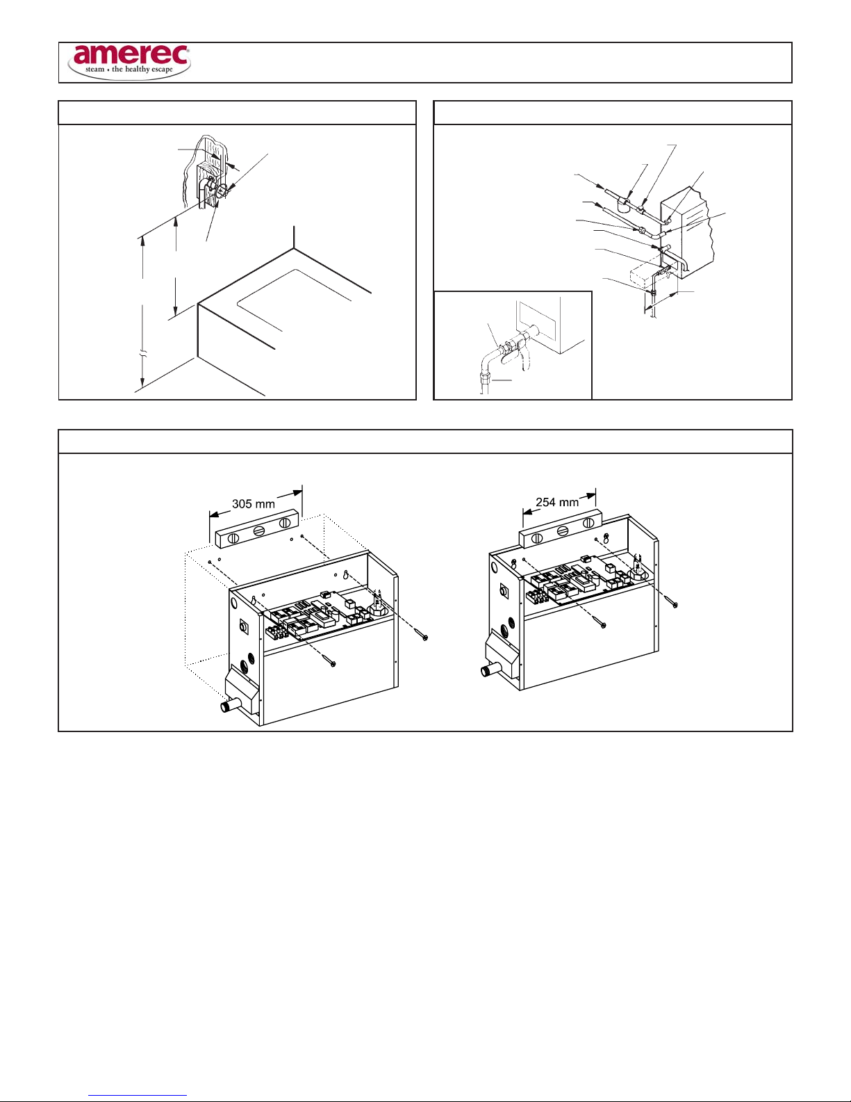
2. TEMPERATURE SENSOR CABLE ROUGH-IN
(REQUIRED FOR K60 OR K30 ONLY)
It is recommended that the sensor be mounted in the
steam room 150 mm from the ceiling, but not directly
over the steam dispersion head or more than 2,1 M
above the floor. String the sensor cable from the
sensor location through 13 mm holes in the wall
studs or ceiling joists to the generator location. Leave
305 mm of slack at the sensor location. Note: Do not
staple through or damage cable. Use factory supplied
cables only.
3. ELECTRICAL ROUGH-IN
Size wire for the generator as indicated by the Elec-
trical Information Chart on page 8. Use correct size
and type to meet electrical codes. Leave 1,2 M of
slack wire at generator location for finish hookup.
Connect the generator to a dedicated circuit breaker.
A GFI device is not required by UL. One may be
installed if required by local codes or the owner. A GFI
device will tend to nuisance trip due to heater element
aging.
4. ELECTRICAL FINISH
Materials (locally available):
- 3/4" Strain relief for supply wire.
A. Route the copper supply wire with appropriate
strain relief through the hole marked POWER ENTRY.
B. Connect the supply wires to terminals marked
230V and N (230V ~ Models) or L1,L2, L3, and N
(400V ~ 3N Models)
C. Connect the ground to the earth ground lug (
).
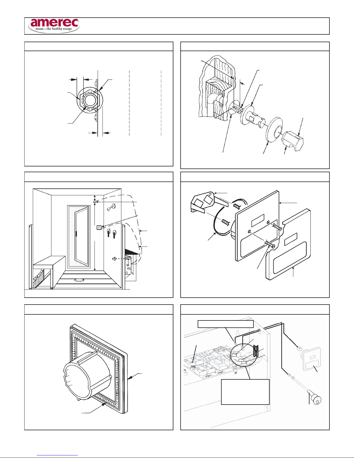
5. INSTALL GENERATOR CONTROL (K30,K60,KT60)
The low voltage controls can be mounted directly to
a finished wall either inside or outside the steam
room with the exception of the KT60 control which
must be mounted inside the steam room. Using a 50
mm hole saw, drill a hole in the finished wall where
the control is to be mounted (the control cable should
already be roughed-in to this location). With the
decorative cover removed from the control switch
assembly, insert the two control mounting screws
through the control housing (may need to punch
through skinned holes) and screw 0,6 mm into the
mounting bracket. Locate the control cable and plug
it into the back of the control housing. See diagram
8. Run a bead of 100% silicon caulk in-between the
2 ridges around the perimeter on the back of the
control housing. See diagram 9. Insert the mounting
bracket into the wall cavity by first pushing with the
control housing and then with a hard flat surface on
the control housing mounting screws which extend
out through the control face. Once the mounting
bracket has been inserted into the finished wall,
center the control and tighten the mounting screws
to draw the control housing securely against the
finished wall. Do not over tighten the mounting
screws. Install the decorative cover plate by sliding
the top of the cover plate over the tab on the top of the
control housing and pushing on the bottom of the
cover plate to complete the snap fit. See diagram 11.
Route the generator end of the control cable through
the generator hole marked CONTROL WIRING EN-
TRY using the strain relief provided. Plug the control
cable into the connector on the printed circuit board
assembly. Insert cable into connector S30 if a K30
control is used or connector S60A if a K60 or KT60
control is used. See diagram 10.
5A. INSTALL GENERATOR CONTROL (R30K)
The low voltage control can be mounted directly to a
finished wall either inside or outside the steam room.
Using a 45 mm hole saw, drill a hole in the finished
wall where the control is to be mounted (the control
cable should already be roughed-in to this location).
Locate the control cable, pull it out through the
45 mm hole and plug the connector on the back of the
control housing. Run a bead of 100% silicone caulk
around the perimeter on the back of the control
housing. See diagram 13. Insert the control into the
wall cavity.
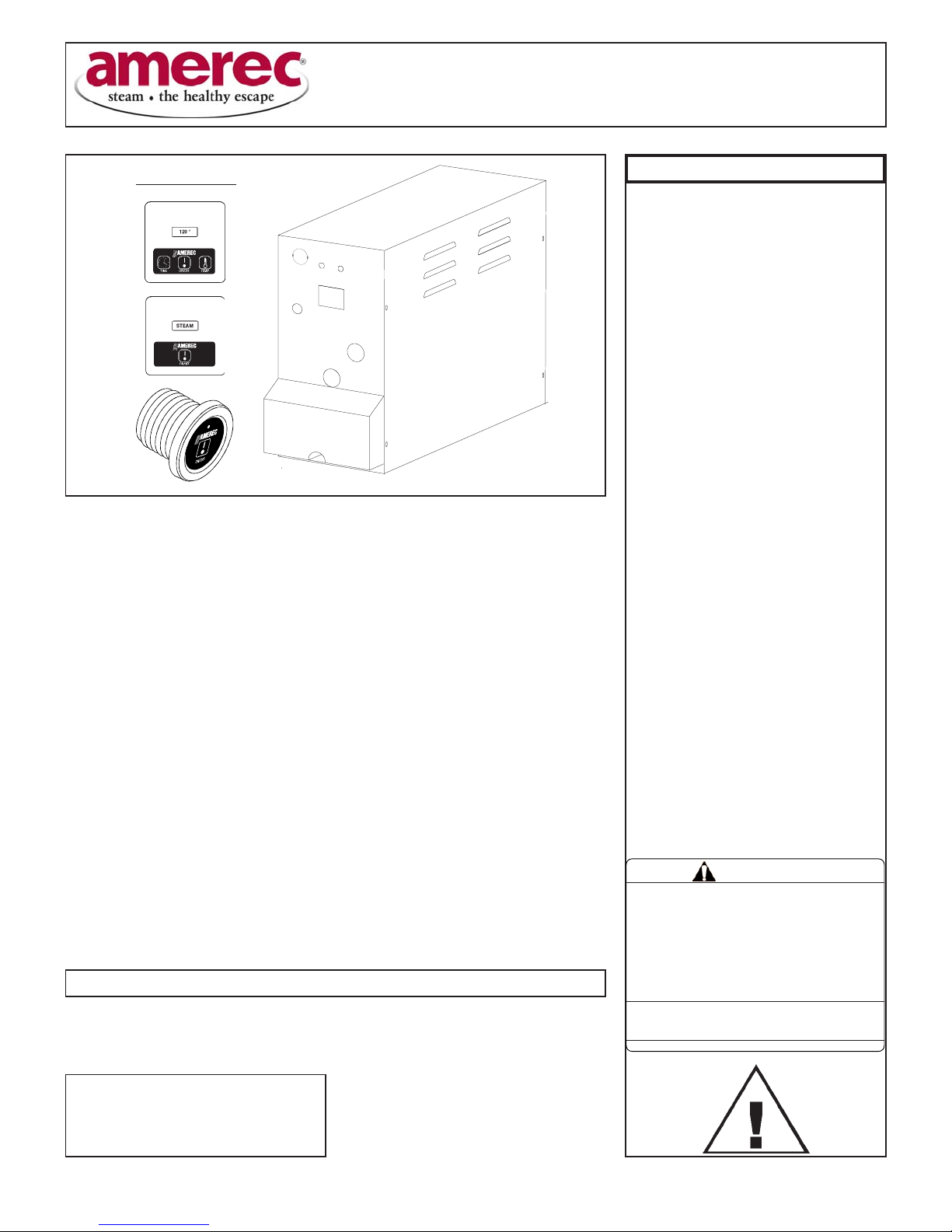
WARNING
SECTION 6: WIRING INSTRUCTIONS
SEE ELEC. INFO. CHART AND WIRING DIAGRAM