AMERI-CAN MACHINERY CS400A User manual


2
WHO IS IT FOR
This manual is intended for the machine user and for the persons in charge of moving, installation, using,
surveillance, maintenance and final dismantling of the machine.
AIMS OF THE MANUAL
The manual explains the correct use of the equipment, as foreseen at the design stage and in the technical data. It
includes instructions for moving the machine as well as for its correct and safe installation, assembly, adjustment and
use, as well as supplying information concerning maintenance interventions and how to order replacement parts.
LIMITS OF USE
This manual is valid only for the machine with the code number it expressly mentions. No information contained in this
manual may be applied of other machine models from different ranges. All of the necessary indications shaJl be taken
from this manual and not from any similar manuals, similar equipment or from other manufacturers.
SYMBOLS
In order to draw greater attention to certain points, this manual contains the following symbols that are divided as
follows:
PROHIBITION WARNING
INFORMATION SPECIALISTS
SPECIALIST ONLY
RESPECT OF LEGISLATION
As well as the regulations specified in this manual, the Customer shall respect the relevant legislative dispositions
concerning accident prevention in the workplace.
CONSERVATION OF THIS MANUAL
This manual is considered to be an integral part of the machine and as such, must be kept in good condition until the
machine is disposed of This manual must be kept in a safe, dry place, away from direct sunlight and it must always be
easily available for consultation in the workplace.
HOW TO REQUEST A FURTHER COPY OF THE MANUAL
In the event that the original copy of the manual is damaged in any way, Customers may, at their own expense, request
an additional copy from the Manufacturer.
INFORMATION FOR THE USER
a) This manual refers to technical conditions at the time of
the sale of the machine.
The Manufacturer reserves the right to modify
products and manuals without the obligation to
upgrade previous products or manual.
b) The characteristics of this manual may be modified at
any time in accordance with technical developments and
with no prior notification.
c) In the event that the equipment is sold on, the
Manufacturer should be informed of the address of the
1. MANUAL USE AND CONSERVATION

3
new owner in order to facilitate the sending of any
additional parts to be integrated into the manual.
d) For further information or clarifications, it is possible to
contact the Assistance Service (see section 13.2)
The Manufacturer declines all responsibility in the event of the following:
■Incorrect use of the machine
» Use of the machine by untrained personnel
» Any use of the machine that contravenes that which is stated in this manual
-Any use of the machine that contravenes the laws and standards in force
» Any use with defect of primary alimentation
■Exceeded of limits service
-Excessive mechanicals stress
The user is required to guarantee that:
■All operations for transport, connection, use, maintenance and repair will be carried out by qualified
personnel
■Qualified personnel are understood to be (as per IEC 364} persons who, in terms of their training,
experience, knowledge of standards, prescriptions, accident prevention provisions and conditions of use
and service, are able to cany out all necessary interventions and to recognise and avoid all possible
danger and/or damage.
" These persons will avail of all of the relevant information and training required, including any local
prescriptions, to which they will adhere when carrying out any operations,
■Unqualified personnel will be prohibited from carrying out any operation even directly on the machine
or equipment.
■During the stages of installation, any local or special prescriptions and/or in any case, all prevention
conditions that have not been discharged will be met using additional safeguards.
2.
MARKING DATA AND DELIVERY CHECKS
Ensure that the equipment shows no signs of damage and that no parts are missing. In the event of damage,
contact the relevant insurance company or the Manufacturer. In the event that the supplied goods are
incomplete, contact the Manufacturer directly. Each machine has an identification plate.
2.1
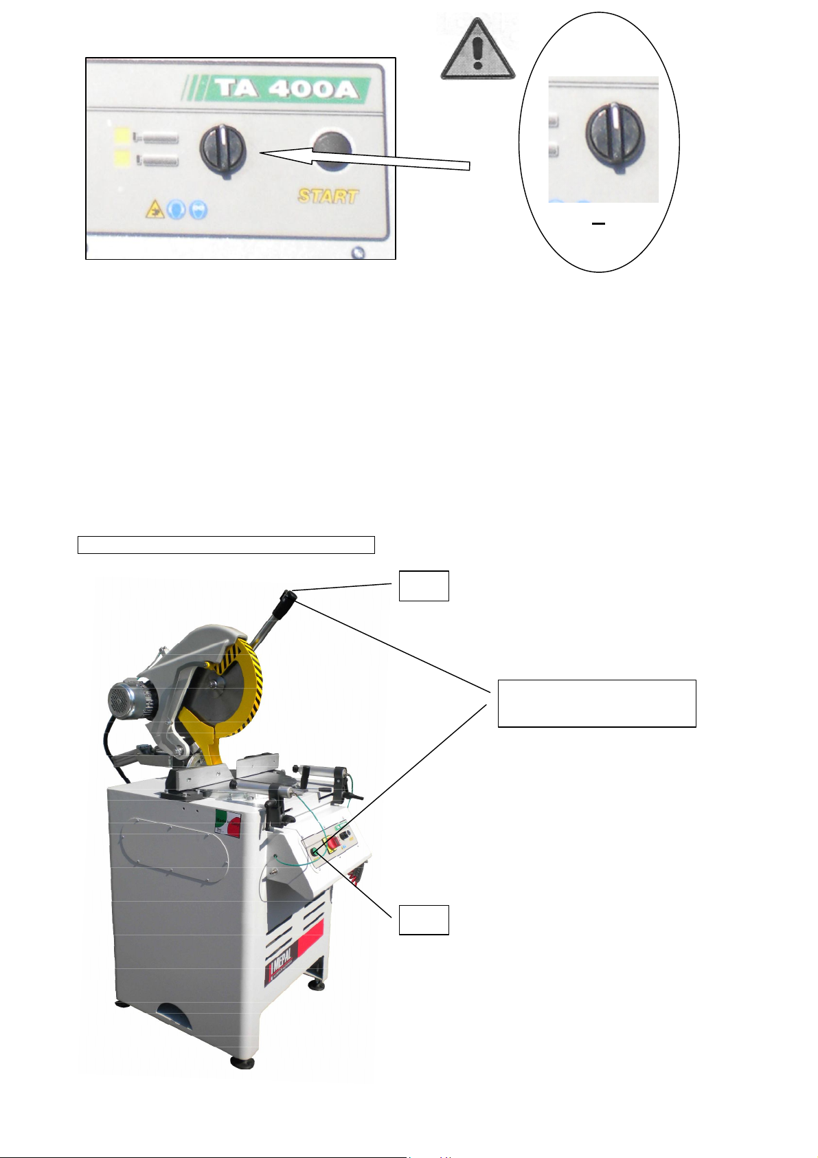
MACHINE IDENTIFICATION PLATE
This plate contains information about the Manufacturer as well as the
model and progressive serial number of the machine. For any
communication.regarding the machine (problems, interventions under
guarantee, replacement parts, etc.) always refer to this plate and to the
information it contains.
2.2 CE
MARKING
The CE marking on the machine means that it conforms to the European Community Directives with regard to Health
and Safety in the workplace.
3.1 HANDLING
Machines are delivered in a protective plastic covering or packed on pallets with crates - wooden crates
cardboard coverings, according to the requirement stated at the time of order.

4
WARNING!!
Once the packing has been removed, the machine may only be moved using a suitable truck.
4. OPERATION NECESSARY FOR THE
INSTALLATION
It is necessary to make sure that the machine is correctly positioned in order to guarantee its stability and to ensure the
correctness of the operator's working position. The machine must be placed in a sufficiently large area to permit the
handling of the material to be machined. The machine must be placed on a flat, horizontal and stable surface that is able
to support the weight of the machine adequately. Furthermore, the machine must be situated in a place that allows its
entire structure to be lit evenly.
4.2
CONNECTIONS
The
sawing machine
must be supplied from two sources: electric and
pneumatic.
The pneumatic inlet (FIG.A) must be connected to a supply of compressed
air using a pipe that withstand a minimum working pressure of 7 bar. A
filter with an automatic condensation discharge outlet must be installed
between pipe and the compressor, as must a tap to intercept the
pneumatic supply. The entire supply system must guarantee a minimum
internal passage with a diameter of 6mm. The machine is supplied pre-
calibrated and if necessary, use the pressure reducing valve (FIG.C) to
adjust the pressure from a minimum of 6 bar to a maximum of 7 bar.
The electrical connections
(FIG.B) must be carried out by specialist
personnel. The connection requirements are as follows: double insulation
cable of type N1WK-3P+T with a section of 2,5 mm2 and a 16 3P+T socket
compliant with EC standards with a thermo magnetic cut-out switch 16A
and ICC short circuit current that is equal to or more than 10 kA. The
electrical connection must be made to a three-phase alternate current, line
50Hz with a voltage of 380.
All stages of installation must be carried out
by qualified personnel
4.1
POSITIONING
A

5
WARNINGI BEFORE SUPPLYING POWER TO THE
MACHINE, MAKE SURE THAT THE CONNECTIONS
HAVE BEEN MADE CORRECTLY IN ORDER TO
PREVENT THE OCCURRENCE OF SITUATIONS THAT
MAY ENDANGER THE OPERATOR.
WARNING! CHECK THE ROTATION OF THE
BALDE.VERIFICARE IL SENSO DI ROTAZIONE DELLA
LAMA. IN CASE THE ROTATION WOULD RESULT ON
THE CONTRARY DIRECTION THEN INVERT TWO OF
THE THREE CABLES L1/L2/L3
5. MACHINE SAFETY AND INTENDED USE
5.
MACHINE SAFETY
WARNING!
Sawing machines, like all other equipment with moving parts, can be sources of serious danger if not correctly used,
protected and maintained.
Safeguards may not be removed under any circumstances
a) The machine has not been designed, built or tested to operate in damp or wet environments, environments with
a high degree of pollution from gaseous chemical substances such as chlorine,ammonia or similar, or in areas at
risk from fire or explosion.
b) The machine has been designed for the use by a single operator.
c) Simultaneous use of the same machine by more than one operator is not permitted.
d) During operation people other than the operator are not allowed to remain in the vicinity of the machine.
5.1
INTENDED USE
These CUTTING OFF MACHINE S are intended for professional use only, they are specially designed and
built to machine light-alloy profiles. Any other type of material is not compatible with the specifications
of the machine.
5.2
WORK PLACE
No particular precautions with regard to the physical or chemical safety of the operator are required for the workplace.
However, the use of suitable gloves to protect against the burrs of the profiles and the shards that are produced during
machining, as well as of safety glasses and head-cuffs, is recommended.
B

6
The machine has not been designed and built to carry out any machining other than that described in this manual. The
operator must avoid carrying out any unsafe operations or operations that are not foreseen as part of machine use and
which could compromise personal safely.
Under any circumstances mav anv machine part {attachments, boring, finishing) be modified or adapted for use with other
devices. MEPAL ITALIA S.R.L. declines all liability in the event of any malfunction caused by failure to respect the above.
Any modifications must be directly requested to and expressly authorized by MEPAL ITALIA SRL
5.4
SWITCHING OFF AND PUTTING OUT OF SERVICE
The equipment is switched off by cutting off the pneumatic and electric power supplies. The machine is put out of service
by removing the air supply pipe and protecting the inlet against dust, shavings, etc... Furthermore, the power cable must
also be removed from the mains electricity.
Several labels have been applied to the router to draw the operator's attention to the care to be taken when using the
machine
5.3
FORBIDDEN USE
5.5
MACHINE BOARD SAFETY LABELLING

7
6. MACHINE COMPONENTS LIST
10
9
11
1
2
5
4
3
7
6
8
18
12
13
14
15
16
17

8
6.1
CONTROL PANEL
A MAIN SWITCH
B OPEN/ CLOSE CLAMPS BUTTON
C START BUTTON A
DESCENDING
CUTTING OFF
MACHINE
1
PROTECTION COVER
10
GENERAL ELECTRIC SWITCH
2
HORIZZONTAL CLAMPS
11
HORIZZONTAL
GONIOME
TER
3
VERTICAL SQUARE
12
START
BUTTON A
4
ROTATING WORKING TABLE
13
START
BUTTON B
5
ROTATION HANDLE
14
OPEN/ CLOSE CLAMPS BUTTON
6
T
ABLE ROTATION LOCKING
15
RETURN CYLINDER
7
AIR PLUG
16
LEGS
8
BLADE LOCKING NUT
17
ROLLING TABLE PREDISPOSITION
9
CONTROL PANEL
18
VERTICAL
GONIOMET
ER
A
B
.
C

9
D START BUTTON B
7.1
PRELIMINARY WORK SEQUENCE
To turn on the cutting off machine
the switch must be activated (A)
7. HOW TO USE
A
.
D

10
Then it is necessary to close the clamps otherwise the blade motor will not run. To close the clamps the
CLAMPS CLOSING BUTTON (B) must be pressed.
IMPORTANT!!!
Start the work sequences below only after a complete reading of this manual
and the consciousness that you understand the correct use of the machine. If
the above mentioned conditions are not respected, serious damage can be
caused to persons and property.
7.2 W
ORKING COMMANDS ACTIVATION
B
BIMANUAL
START
BUTTONS
13
12

11
After the clamps are closed and the switch is activated, it will be possible to start
the blade motor. Press both the (13) and (12) buttons to start working. If one of the
two buttons is released the blade will stop and return to the original position. This
is necessary because the machine must stop if both the hands are not used.
7.3
WORKING PHASE
Press both the (12) and (13) start buttons, the blade protection cover will open while the blade
descends. When the cutting is completed release the (13) start button following the blade rising
without releasing the lever.
When the head will be in the original position and protection blade cover will be closed, the
clamps can be opened and the piece removed.
Move the angle of the rotating table
and leave it in the desired cutting
position. Lock the profile with the
clamps.
When the working is completed, leave
the head in the original position and
unlock the clamps to remove the
profile.
8. CLAMPS

12
As previously said, for security
reasons, it is not possible to start
the machine if the clamps are not
closed.
WARNING!!!
BE SURE IN EVERY WAY OF THE CORRECT POSITIONING OF THE PROFILE BETWEEN WORKING
TABLE AND CLAMPS.
9
9.1
VERTICAL CLAMPS
REGULATION:
:
To regulate the vertical clamp movement :
Unscrew the jackart (A)
Move the clamp support (B) up or
down till the desired position is
reached then lock the jackart (A).
9
.
CLAMPS REGULATIONS
9.2 HORIZZONTAL CLAMPS
REGULATION:
To regulate the horizzontal clamp movement:
Unscrew the jackart (A)
Move the piston (B) forward or bakward
till the desired position is reached then
lock the jackart (A).
A
B
C
B

13
10.WORKING TABLE REGULATION
Example. Rotate the table till it is
positioned to the 45°reference (B) if you
need a 45° cutting.
If the machine does not cut properly
in one of the imposted angles
(0°/45°/-45°), regulate with a key the
locking eccentric pin (D) till the cut
will be the most accurate.
To cut at intermediate angles just leave
the table in the intermediate position
then turn the lever (A) in the arrow
direction.
B
D
D
D
A

14
12.
TECHNICAL DATA
DESCENDING
CUTTING OFF
MACHINE
HEICHT H
mm
1
72
0
MAX PRESSURE bar
10
WIDTH L mm
73
0
BLADE MOTOR rpm
2800
DEPTH P
mm
110
0
MOTOR POWER Hp
2
WEICHT kg
140
AUTOMATIC MOTOR MOVING
WORKING TABLE HEIGHT mm
97
0
WORKING PRESSURE bar
7
BLADE SHAFT mm
30
MIN PRESSURE bar
7
11.
REPLACING THE BLADE
To replace the blade follow these instructions:
Be sure that the head is in the original position (the
(A) cylinder must be closed) and the main switch
must be turned off.
- Remove the locking sieger (D) of the lever so the
blade protection cover (C) will be free to enter inside
the head and a passage will opened for the blade.
-Remove the belt cover on the other side.
-Lock the blade with the allen wrench and remove the
nut (E) with a 19 mm open wrench.
-Remove the blade flange (B), remove the blade and
replace it.
-Follow the same operations in the opposite order to
lock the blade.
H
P
L
B
C
A
D
E

15
13.
CUTTING DIAGRAMS

16
WARNING!!
It is important that qualified personnel carry out periodical maintenance, inspections
and servicing of the unit used in order to avoid those breakdowns that may, directly or
indirectly, cause damage to people, animals or property.
1
4
.1
SETTING UP FOR MAINTENANCE
Before proceeding to carry out any maintenance, it is necessary to cut off the electrical and pneumatic supplies to
the machine ( remove the plug from the mains electricity and remove the pneumatic supply pipe).
14.2
MAINTENANCE PROGRAM
It is important to carry out the following maintenance operations on a regular basis:
-Clean the machine regularly in order to guarantee good working order and paying particular attention to
the organs in movement,
WARNING!!! DO NOT USE JETS OF WATER TO CLEAN THE MACHINE AND ESPECCIALLY ON
ELECTRICAL PARTS.
Lubricate the machine tools with coolant cutting fluid so that these will never operate when dry. In this way the
machining finishes are improved and the useful life of the tools is greatly increased,.
Variations in normal working conditions (noise, vibration, etc.) are indicative of incorrect machine operation, In
the event of problems or the need for repair interventions, contact our assistance service or that of our dealer, In
any case, follow the instructions contained in this manual for any type of maintenance and/or repair
intervention,
For anything not expressly contained in this manual it is necessary to contact the local Assistance Service
(section 14.2).
14.3
SPECIAL MAINTENANCE
Contact the Assistance Service directly (section 14,2)
14.4
ROUTINE MAINTENANCE
The routine maintenance that are usually requested on this machine are:
14.
INSTRUCTIONS FOR MAINTENANCE
Periodically replace the cooling lubricant that is
contained in the relevant tank (B). failure to observe
this rule will invariably cause machining to be
rougher and the mills to wear out more rapidly In
the event that increased tool lubrication is required,
use the regulator (C) of the exit of the cooling
soupape which is placed inside of the machine near
the blade.
BC

17
15.1
COMMON PROBLEM LIST
PROBLEMS CAUSE SOLUTION
THE MACHINE DOES NOT START
Main switch not enabled
Enable switch
THE MACHINE STOPS DURING
OPERATIONS
Missing phase
Enable phase
Thermal overload
Find the cause and eliminate it
BAD CUTTING
Worn blade
Replace blade
Insufficient lubricant
Ad
d lubricant
THE LUBRICANT DOES NOT ARRIVE
Lubricant finished
Replace lubricant
Lubricant circuit blocked
Check oil cleanness or blow
compressed air through the atomiser
connection
ANOMALOUS WEAR OF
PNEUMATIC PARTS
Lack of lubricant in the pneumati
c
system
Add lubricant
Compressed air not purified
Replace filter
Water in the pneumatic system
Check and clean outlets
THE MACHINE DOES NOT CUT
PROPERLY AT 90°
Eccentric pin moved
Section 11
THE MACHINE DOES NOT CUT
PROPERLY AT 45°
Eccentric pin moved
Section 11
15.2
CUSTOMER CARE
The Assistance Service network is available both nationally and internationally. For specific problems, pis contact THESE
NUMBERS:
TEL.:
FAX:
15.HOW TO SOLVE ORDINARY PROBLEMS

18
WARNING!!
WHEN THE MACHINE IS TO BE DECOMMISSIONED BECAUSE IT HAS BECOME OBSOLETE OR IT HAS
IRREMEDIABLY BROKEN DOWN, IT MUST FIRST OF ALL BE PUT OUT OF SERVICE BY BEING
RENDERED INOPERATIVE AND ANY DANGERS REMOVED. DISCONNECT THE MACHINE FROM THE
MAINS ELECTRICITY, DISCONNECT THE AIR PIPES AND REMOVE ALL TOOLS AND ADDITIONAL
PARTS. COVER THESE ELEMENTS WITH PROPERLY SEALED WRAPPING. SEAL THE MACHINE INSIDE
STURDY PACKAGING AND PROCEED TO ITS DISPOSAL IN CONFORMITY WITH THAT SPECIFIED IN
THE STANDARDS AND REGULATIONS IN FORCE. CONTACT THE RELEVANT LOCAL BODIES FOR THIS
OPERATION.
ELECTRIC DIAGRAM

19
PNEUMATIC DIAGRAM
This manual suits for next models
1
Table of contents