IMER COMBl 250/1000 VA Guide
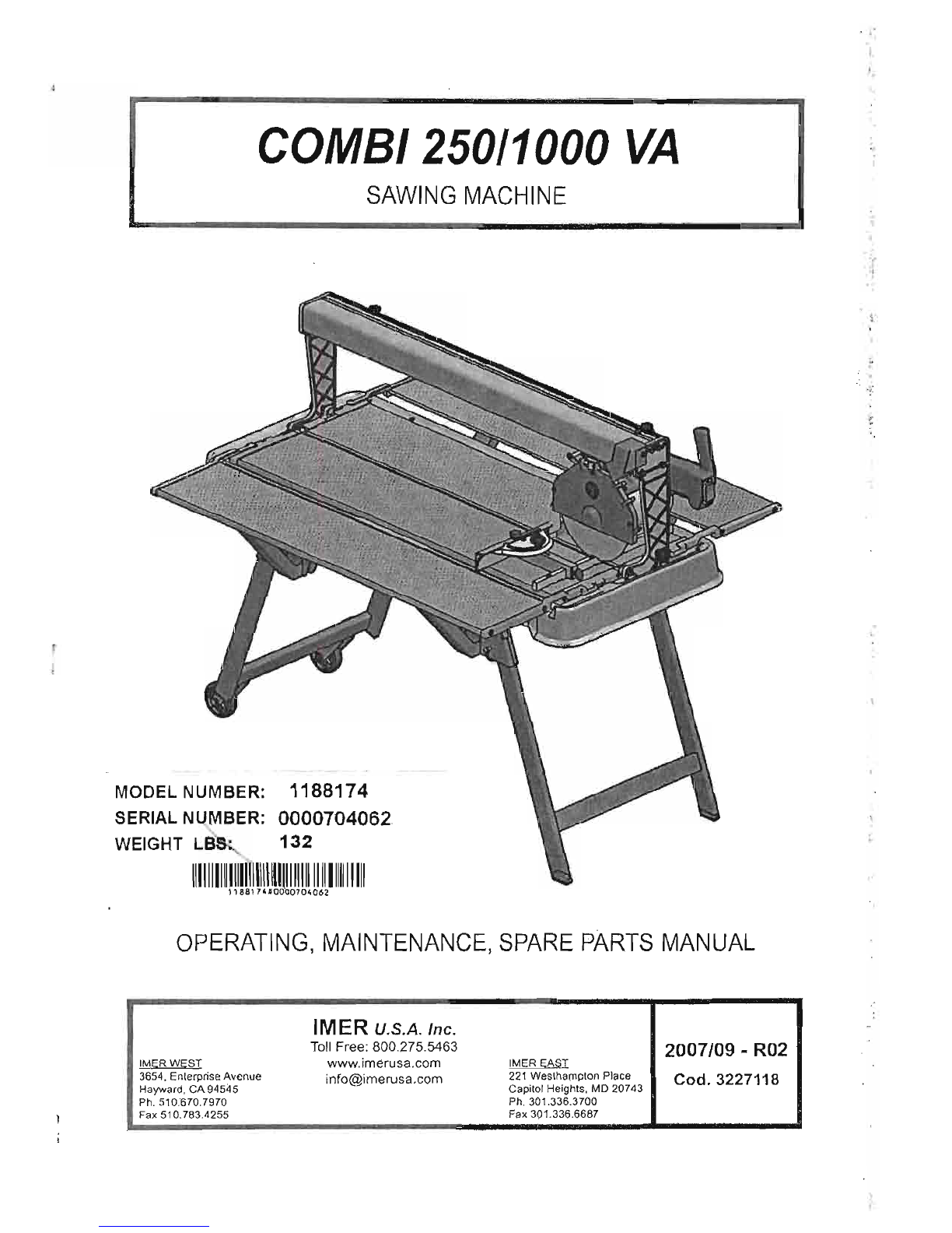
COMBl250l1000
VA
I
SAWING
MACHINE
'188174'0000704062
OPERATING,
MAINTENANCE,
SPARE
pARTS
MANUAL
1IIIIIIIIIIIIIUlI\li~1l11l111111111111111111
MODEL NUMBER:
SERIAL NUMBER:
WEIGHT LBS;.
1188174
0000704062
132
.'
.
"
~:
'.
IMER U.S.A. Inc.
Toll
Free: 800275.5463 2007/09 -R02
IMERWEST
www.imerusa.com IMER EAST
3654, Enterprise Avenue [email protected]
221
Westha!T1plon Place Cod. 3227118
Hayward,
CA
94545 Capitol Heights, MD 20743
Ph. 510.670.7970 Ph. 301.336.3700
Fax 510.783.4255 Fax 301.336.6687

~J
.'
~
IMER INTERNATIONAL S.p.A.
COMBI 25011000
VA
available
for
consullalion.
Dear
Customer,
Congratulations
on
your
choice
of
purchase:
(MER
saws
ore
the
resull
of
years
of
experience
and
are
equipped
with
all
Ihe
lalesl technical
innovations.
Lt
-
WORKING
IN
SAFETY
To
work
in
complete
safety,
read
the
following
instructions
carefully
be-
fore
using
the
machine.
To
work
in
complete
safety.
read
the
(ollowing
instructions
carefully
be-
fore
using
the
machine.
This
OPERATION
AND
MAINTEi'JANCE
manual
must
be
kept
on
site
by
the
person
in
charge,
e.g.
the
SITE
FOREMAN.
and
must
always
be
. .
I
Featur.
Power(1<W)
Ra~ed
'1ollage
M
Frequency
(Hz)
Absorbed
curranl
Number
01
poles
rpm
Service
type
Insulation
category
Proteclion
calegory
Capacitor
(~F)
Tabre
2
MOlor
(115VI60Hz)
1.1
115
60
14.4
2
3400
S640%
F
IP55
--
110
(0
50x\20)
.,.
•
t
:."
,'-,,'
.'
.f
.
.'
~.
"
"
t~.
'
!.
;
;'.\
,.
The
manual
is
to
be
considered
integral
part
of
the
machine
and
must
be
kept
for
future
reference
(EN
12100(2)
unlillhe
machine
is
disposed
of.
If
the
manual
is
damaged
or
lost,
a
replacement
may
be
requested
from
the
manufacturer.
The
manual
contains
important
information
regarding
site
preparation,
machine
use,
maintenance
procedures,
and
requests
for
spare
parts.
Nevertheless,
the
installer
and
the
operator
must
both
have
adequate
experience
and
knowledge
of
the
machine
prior
to
use,
To
guarantee
complete
safely
of
the
operator,
safe
operation
and
long
life
of
equipment,
follow
th.e
instructions
in
this
manual
carefully,
and
observe
all
safety
standards
currently
In
force
for
the
prevention
of
ac-
cidents
al
work
(use
of
safety
footwear
and
suitable
clothing,
helmets.
gloves,
goggles
etc.).
Lt
-
Make
sure that al/ signs are legible.
Lt
-It is strictlyforbidden
to
cany
O!it any form
of
modification
to
thCl
steelstructure.or working parts
of
the machine.
IMER
INTERNATIONAL
declines
all
responsibility
for
failure
10
com-
ply
with
laws
and
standards
governing
the
use
of
this
equipment,
in
particular;
improper
use,
defective
power
supply.
lack
or
maintenance,
unauthorised
modifications,
and
partial
or
tolal
failure
to
observe
Ihe
instructions
contained
in
thiS
manual.
IMER
INTERNATIONAL
reserves
Ihe
right
10
modify
features
of
thll
saw
and
contents
of
this
manual,
without
the
obligation
to
update
previous
machines
and/or
manuals,
1,
TECHNICAL
DATA
Technical
dala
are
stijted
in
lable
1
and
electrical
specifications
in
table
2.
i
Table
1•
TECHNICAl.
DATA
Model
Combi
25011000
VA.
i
Max.
blade
dlameler
10
inches
Diamond
Blade
hole
diameter
5/8
inches
Single
·pheslr
115V/60Hz
motor
power
1,1
kW
Max.
blade
mUllion
speed
3400
rpm
i
Culling
lnble
dimension5
1115x500mm
Length
of
90'
culs
(thickness=<
10mm)
Length
or
culs
from
aboye
950mm
1.000
mm
I
Maximum
cul·depth
with
single.
stroke
I
Maximum
cut
depth
with
lWo
stroke
6Gmm
105mm
Waler
pump
now
rale
13Vmln
Waler
tank
capacity
40
L
Machina
dimensions
1420x636x619
Packed
machine
dimensions
1455x670x653
mm
Weight
with
packaging
65
kg
2
DESIGN
STANDARDS
Combl
250/1
OOOVA
saws
have
been
designed
and
manufactured
accor-
ding
to
the
foilowing
standards:
EN
12100-1-2;
EN
60204-1;EN
12418.
3
SOUND
PRESSURE
LEVEL AND
VIERA
TlONS
Table
3
shows
the
sound
pressure
level
measured
load
less
allhe
ope·
ralor's
ear
(L.
A)
and
of
the
vibrations
transmitted
during
operation.
Table
3
Sawing
machine
I
Typa
of
motor
L,.,
A
...
II
Combi
250/1000
VA
I
Electric
I 86dS I
2.57
mis'
4,
GENERAL
SAW
DES~B.lEIlQti.
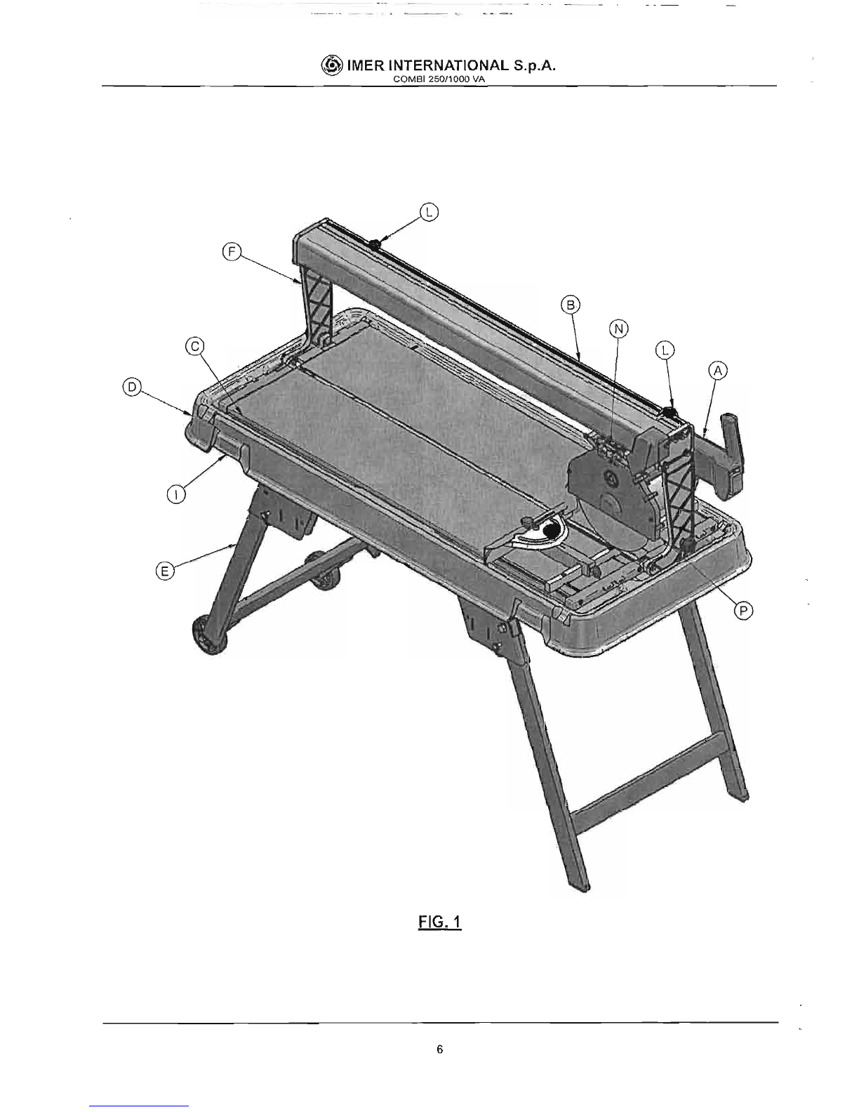
41 General description
The
Combi
250/1000
VA
is
a
saw
comprising
the
following
main
sub-
groups:
•
culter
hea\!
(reLA,fig.l)
•
runner
guide
and
anns
(ref,B,
fig,l)
•
cutting
tables
and
heads
(reLC,
fig.1)
•
water
collection
tank
(ref.D,
fig.
1)
'frame
(ref.E,
fig,1)
The
culling
head
is
mounted
on
a
reinforced
aluminium
profile
and
is
equipped
with
horizontal
and
vertical
movement
facilities.
The
alumi-
nium
profile
is
hinged
onto
die-cast
arms
(ref.F,
fig.1)
and
01e
entire
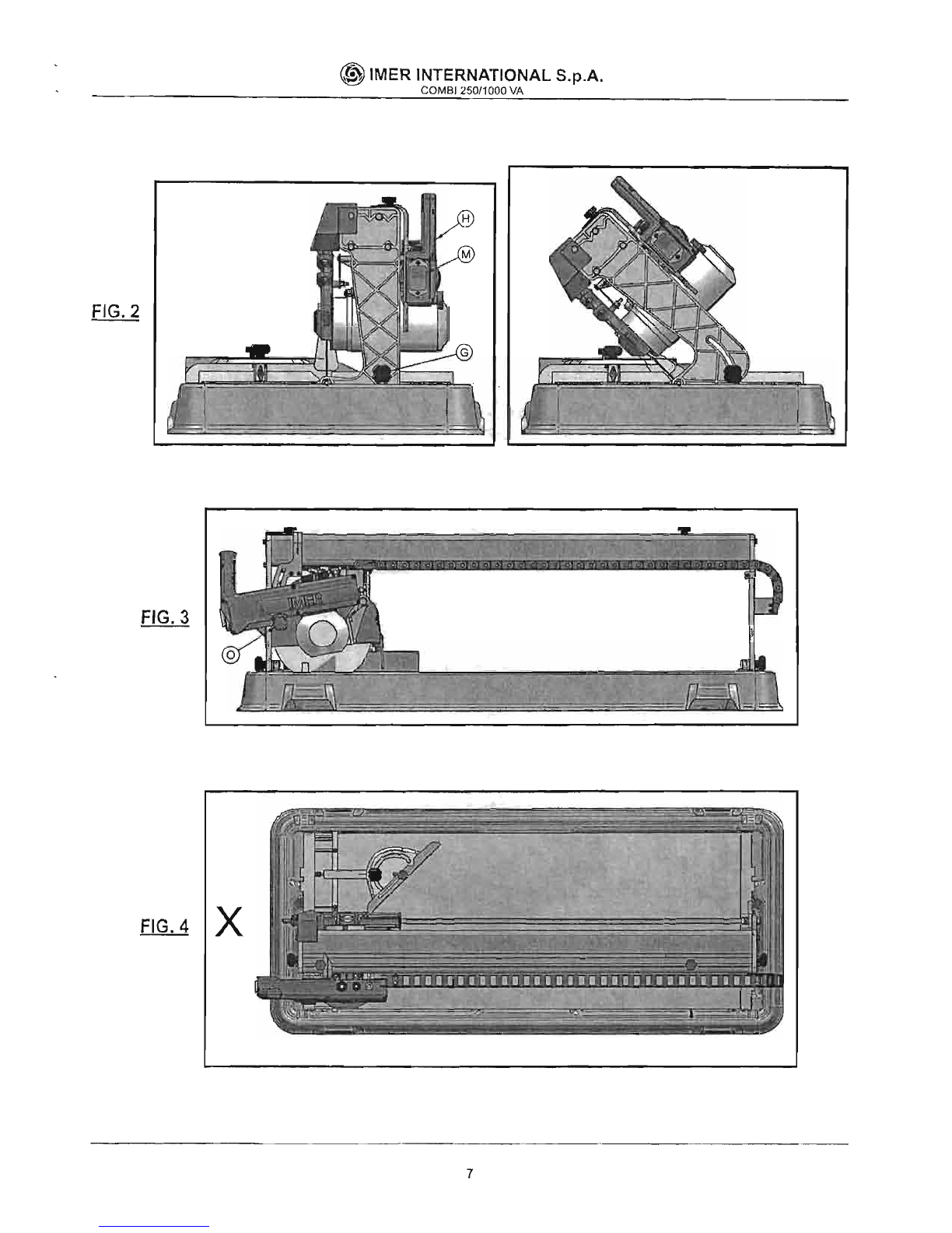
unit
can
rolale
through
45'
(f1g.2)
by
mClans
of
lhe
relative
handwheels
(ref.
G,
rtg.2).
The
machine
Is
supported
by
a
special
metallic
frame.
There
is
a
shock-
proof
plastic
tank
between
the
machine
and
the
frame,
The
water
im-
mersion
pump
is
mounted
below
the
cutting
surfaces
on
a
special
brac-
ket
and
supplies
a
water
distributor
inside
the
blade
guard
for
cooling
the
culling
btade
during
operation.
The
high
resistance
plastic
handle
(ref.H.
fig.2),
is
equipped
with
the
main
ON-OFF
switch
on
the
operator
side
to
facilitate
saw
activation
and
shutdown.The
raised
position
of
the
red
OFF
bUlton
on
the
hand-
le
is
designed
to
facililate
shutdown
of
the
machine
in
the
event
of
an
emergency.
The
motor
capacitor
is
located
in
a
protected
position
inside
the
handle.
The
saw
is
fitted
with
a
guard
to
guarantee
optimal
safety
during
0Pera-
lion
and
to
protect
the
user
during
culUng
cycles.
Avalve
is
mounted
above
the
blade
guard
to
adjuslthe
now
rate
of
water
delivered
to
the
cutting
blade.
4.2
P(Q.cessable
materials
This
saw
has
been
designed
for
cutting
the
following
materials:
ceramic
tiles,
masonry
and
stone
in
general
with
maximum
dimensions
com·
patible
with
the
length,
cutting
depth
and
dimensions
of
the
surfaces
specified
in
lable
1.
Maximum
weight
01
processable
materials:
25
kg.
~nsuitable
material
Materials
unsuitable
for
this
machine
are
all
those
not
specified
in
pa-
ragraph
4.2.
In
any
event,
before
using
the
saw
with
materials
other
than
as
specified
by
the
manufacturer
for
this
saw
model,
conlacllMER
INTERNATIONAL
Sf
A
& .
Use
of
this machine with workpieces outside
the
specified
dimensions is
strictly
prohibited and constitutes a hazard for
the
operator.
""
.
. r t
'-.t-
2
;~
,
,.
'.,
tJ>.~.
~
JMER
INTERNATIONAL S,p.A.
COMB1.250'1000
VA
5,
OPERATION SAFETY
ill
-Before
using
the saw, ensure that
all
protection
devices are
filled,
ill
-Never use the saw in environments subjeci
to
the risk
of
explosions
or
fire.
The
saw
is
not
filled
wilh
specinc
lighting
and
therefore
the
workplace
must
be
sufficiently
lit
for
this
purpose
(min.
300
lux.).
The
power
lines
muslbe
laid
to
prevent
any
possible
damage,
Ensure
that
the
eleclrical
connection
is
protected
againstlhe
risk
of
wa-
ter
penetration
in
connectors.
Use
exclusively
conneclors
and
couplings
equipped
with
water
spray
protection.
Never
use
inadequate
or
makeshift
electrical
lines
or
cabtes
without
ear·
thing;
if
in
doubt
consult
aspecialised
.technician.
Repairs
to
the
electrical
circuit
must
be
performed
exclusively
by
specia-
lised
personnel.
Disconnect
Ihe
machine
from
the
power
supply
before
performing
maintenance
or
repairs.
6.
GENERAL SAFETY WARNINGS
Nole
that
this
machine
has
been
designed
to
ensure
optimal
performan-
ce
and
maximum
safety;
however
the
operator
must
also
guarantee
this
level
of
safety
by
paying
special
atlenlion
10
the
machine
throughoul
all
work
phases.
1.
Ensure that
an
efficient earthing system is installed.
2.
Work only with all
protection
devices fitted correctly and In effi-
cient working order.
3.
Keep
the
machine clean: general cleaning (and the work surfa-
ces in partiCUlar) represents
an
important safetyfactor.
4.
Always stop the machine and disconnect from the
power
supply
before cleaning
or
removing
any
protection
device
(for
maintenan-
ce
or
disassembly purposes).
If
water jets are used
for
cleaning,
never
point
jets
directly at the
power
supply
unnor
electric motor.
5.
Remove rings, watches, bracelets
or
ties be/oro using fhe ma-
chine; these elements constitute a serious hazard
to
the operator.
Also ensure that sleeves are tIght
around
the wrists, hair Is tied
back and
robust
footwear is used.
6.
Never cuI workpleces that· have dimensions
or
weight thaf are
not suited
to
machine I capacity as speciffed
by
the manufacturer
(see
point
4.2)
7.
Always use personal
protection
devices such as safety goggles,
SUitably sized gloves, ear muffs
or
plugs
and
hair
caps when ne-
cessary.
8.
Use
original diamond blades
as
recommended
by
the manufac-
turer to ensure optimalperformance
of
the machine.
9.
Always keep hands well away from the working zone while the
machine Is running; before removing workpieces from the blade
area, always press the
stop
pushbutton'
to
shut
down rotation.
10.
The
Instructions in this manual are aimed at machine users
(operafors, maintenance engineers).
11.
Never use diamond blades that are
chipped
or
deformed.
12.
Never use blades over tire rotation speedspecfffed
by
the ma-
nufacturer.
13.
Use exclusively water-cooled
continuous
rim blades suited
to
the material
fo
be
cut.
14.
Never
dry
cut material
or
cut
when cooling water levels are
low.
7.
SA
EETY DEVICES
The
Combi
25011000
VA
has
been
constructed
taking
into
account
cur-
rent
hannonised
European
safety
standards.
According
10
machine
directive
981371EEC
all
safety
devices
have
been
installed
wilh
the
aim
of
safeguarding
the
operator,
7.1
Guards and safely devices
The
machine
is
equipped
with
fixed
guards,
secured
by
means
of
screws
and
protections
Ihat
prevent
access
10
moving
or
dangerous
parts.
All
fixed
guards,
covers,
shieldS
fixed
by
means
of
screws
have
been
envisaged
to
protectlhe operalor
(maintenance
engineers.
technicians
and
others)
from
possible
accidents
cause
by
electrical
discharge
or
moving
mechanical
parts.
Therefore
use
of
the
machine
with
guards
removed
or
modified
in
any
way
is
strictly prohiblled.
ill
'Before performIng maintenance
or
repaIrs to the machliJe,
turn It
off
via the maIn switch and disconnect from the
power
sup-
ply
to prevent Inadvertent start-up
and
isolate
all
machine electri-
cal cirCUits.
8.
MACHINE INSTALLATION
~
Remove
the
machine
packing.
The
machine
can
already
be
uSf;d,
leaVing
the
legs
folded,
resting
its
frame
on
asulnciently
even
surtace
at
least
as
big
as
the
tank.
Frame
assembly:
1,
remove
Ihe
machine
and
tank
from
the
folded
trame.
2.
remove
the
safety
pins
from
Ule
frame
and
open
the
legs.
3.
put
the
satety
pins
back
in
(he
holes
provided
locking
the
legs
in
Ihe
open
position.
4.
reposition
the
machine
and
tank
on
lhe
frame.
ill
-Make sure that the frame is
positioned
on aflat andeven sur-
face, capable'
of
bearing the weight
of
the machine. The maximum
permissIble gradient in a/l directions
Is
6°.
8,2 Handling
The
Comb!
250/1000
VA
sawing
machine
weighs
57
Kg
C!nd
can
be
mo-
ved
using
the
side
handles
on
the
tank
(ref.l,
ftg.1).
For
short
distances
use
lhe
wheels
filled
on
the
frame.
For
longer
distances.
before
moving
the
machine,
close
the
frame
reversing
the
sequence
of
the
operations
described
in
point
8.1.
Every
time
the
machine
is
moved,
make
sure
the
head
is
IO.cked
tighte-
ning
the
knobs
(ref.L,
fig.
1j.
ill
-Always empty the tank before moving the machine.
ill
-Always disconnect the
power
plug
before mOVing the ma-
chine.
~Qnal
table assembly(optlOnllJ
kit
code
11881761
The
additional
table
can
be
positioned
on
the
right
or
left
side
of
!he
machine
or
on
both
sides
althe
same
time.
Firslly
insert
the
props
(two
for
each
table)
in
lhe
grooves
provided
on
the
chosen
side,
Al
Ihis
point
you
can
install
the
additionallable,
Which
is
supplied
with
the
side
supports
already
assembled.
Insert
these
supports
completely
in
the
special
housings
machined
in
the
machine
sides.
Then
lower
the
additional
table
until
ilis
on
level
with
the
machine
table
(fig.6).
ill.
The
use
of
addltfonal tables without
props
can
cause damage
to them.
9,
ELECTRICAL CONNECTION
& .Ensure that voltage corresponds to machine dataplate spe-
cifications.
The
power
supply
line
must
be
equipped
with
current
overload
protec-
tion
(e.g.
thermal
cutout)
and
protection
against
indirect
conI
act
(e.g.
residual
current
circuit
breaker).
Conneclthe
machine
to
an
efficient
earthing
system.
The
size
of
the
power
cable
wires
must
be
based
On
operating
current
and
length
of
the
power
line
to
prevent
excessive
vollage
drops
(table
4).
Table
4
IV
115
Cable
length
(rn)
I
0+12
I
13'
20
I
21
.32
J=
14.4A
Cable
(mm') I
1.5
I
2.5
I4
Connect
the
saw
plug
to
the
mains
and
lighten
the
mechanical
retainer
ring
with
IP67
protection
rating.
The
saw
is
now
ready
for
operation.
3
~
IMER INTERNATIONAL S.p.A.
COMB1250/1000
VA
10.
MACHINE
USE
10.1
Ooeration
The
correct
sid.e
for
the
operator
is
shown
in
fig.4
reLX.
Fililhe waler
tank
10
lhe
ma.>\imum
level
(approx.
40
Hires).
Connect
the
machine
to·lhe
power
mains
and
star1
as
described
In
pa-
ragraph
10.
Open
the
valve
(reLN,
fig.1)
and
ensure
sufficient
flow
of
cooling
water
to
lhe
diamond
Olade.
10.2
Cutting
Restlhe
material
to
be
cut
on
the
culling lable against
the
stopper.
De·
fine
lhe
required
inclination
using
the
goniomeler.
To
adjusl
the
culling
head
heighl.
loosen
the
handwheel (reLa.
f.g.3).
position
the
head
at
the
required
height,.
then
fully
lighten
the
handwheel.
Make
sure Ihal
handwheels
for
sloped
cUlling
(ref.G,
fig.2)
are
firmly
tightened.
Slart lhe
sawing
machine
as
described in paragraph
10.
To
proceed
wilh
cutting.
press
the
piece
10
be
cui
on
the
lable
with
your
hand
and
move
the
cutter
head
gripping
the
handle
and
drawing
it
towards.
you.
If
the
feed
speed
is
too
fast
in
relation
10
the
lhickness
and
hardness
of
Ihe
malerial
the
blade
mighl
stop
turning.
In
this
case.
release
the
disk
as
quickiy
as
possible
moving
the
culler
head
away
from
you
unlillhe
disk
recovers
its
nominal
rolalion
speed.
Resume
cuHing,
adjusting
the
feed
speed
according
to
lhe characteristics
of
Ihe
material.
10.3
Angled cuts
Loosen
the
handwheels
(ref.G,
fig.2),
set
Ihe
culling
head
althe
requi-
red
angle,
retighten
the
handwheels,
and
proceed
as
described
in
the
poinl
above.
&.
Ensure
thafthe
tank is kept
full
during allwork phases and in
the event
of
prolonged work Intervals replace water regularly and
remove allprocessing residue.
10.4
Laserpolnter
The
machine
is
filled
with
a
laser
pointer
that
reproduces
the
culling
line
on
lhe
piece
being
machined.
TIle
track
of light indicates
the
Irajeetory
of
lhe
diamond
disk
during
Ihe
feed
motion.
Making
the
required
CUlling
profile
coincide
wilh
the
laser profile,
it
is
possible
10
ensure
lhe
highesl
accuracy
of
the
operation.
Cuts
at
right
angle
with
one
side
of
the
piece
being
machined
do
not
require
tracing
beforehand:
in
facl
il will suffice
10
make
sure
that
the
side
of
reference
is
in
coni
act
with
the
stopper
on
Ihe
resting
surface.
Ukewise.
using
lhe
goniometer.
CUlling
at
predefined inclinations
is
pos-
sible.
The
laser
light
will
indicate
the
actual position
of
the
cut.
The
taser
pointer
is
activated
when
the
machine
is
connected
to
lhe
e/eclric
mains.
The
pointer
is
aligned
wilh
the
disk
and
must
not
be
moved
from
its
initial
position.
& -
The
pointer used emits alow powerlaserlight. butit Is
In
any
case advisable to avoid looking directly at the emitter itself.
11.
MAINTENANCE
11,1
Premise
Routine
meintenance
operations
can
also
be
performed
by
non-speci"li·
sed
personnet
provided
thai
all
safety standards
specified
in
lhe
ralative
sections
of
this
manual
are
observed
at
all
times.
11.2
Machine cleaning
The
machine
should
be
cleaned
exclusively
when
it
is
stationary.
& .
All
power switches must be set to
"0"
and plugs must
be
disconnected from the mains.
1.
Never
use
compressed
air:
Ihis
could
cause
infiltration
of
dust
or
reo
sidue
in
enc.losed
parts.
2.
Ensure
Ihat
the
cooling
water
nozzles
are
not
obstructed.
3.
Above
ali
the
cooling
water
in
lhe lank must
be
changed
every
day.
4.
00
not
use
detergents
or
lUbricants.
11,3
Waste
disposal
As
regards
disposal
of
processing
wasle
observe
all
current
legislation
in
lhe
country
of
use.
11,4
Repairs
Repairs
10
the
electrical installation
must
be
performed
el<c/usively
by
specialised
personnel.
Use
exclusively origlnallMER
spare
parts:
modi-
fications
to
paris
are.
strictly prohibiled.
The
special
design
of
the
Combi
4
250/1000
VA
ensures
that
no
other maintenance olherthan
as
specified
above
is
required.
Ensure
thai
the
conlacts
of
Ihe
power
plug
and
plug-switch
assembly
are
efficient.
If
oxidation
is
detecled,
clean
iinmedialely
& .
In
Ihe event
of
activation
of
the
RCCB,
check the machine
and arrange
(or
repairs
If
necessary eXclusively by specialised
personnel.
11
5 Clffaning the tank
Clean
lhe
tank
in
the
event
of
build-up of sediment
on
lhe
base,
or
at
least
once
a
day.
Failure
to
clean
1l1etank
could
impair
operation
of
the
immersion
pump
used
for
circulation
of
lhe
diamond
blade
cooling
water.
To
clean
Ihe
lank, disassemble
from
lhe machine,
lock
the
head.
hold
it
by
Ihe
arms
and
rinse
with
a direct water jet (Ihis
Is
to
avoid
direct
con-
tacl
of
the
waler
with
electrical
parts),
the
proceed
with
manual
cleaning
using
cloths
or
brushes.
Take
care
nOl
to
damage
cables
When
replacing
the
machine
on
the
tank
Take
care
not
to
damage
the
pump
wilen
placing
the
machine
on
lhe
surface
11.6
Blade replacement
The
diamond
blade
is
made
of
materiaf
that
may
be
damaged
when
subject
10
high
temperalures,
and
therefore
must
be
cooled
during
the
work
phases.
To
replace
the
blade,
proceed
as
follows:
1.
Blo.elI
axial
movement
of
the
cutting
head
by
means
of
the
hand-
wheels
(ref.L.
fig.
1).
2.
Disassemble
Ihe
front guard
(reLP,
fig.1).
3.
Loosen
lhe locknut
by
rotating clockwise (left
thread),
using
a
19
mm
wrench.
4.
Move
the
cutting
head
forward
slightly
and
incline
10
remove
the
blade
from
its
seaL
5.
Ensure
thallhere
are
no
foreign
objects
between
the
fixing
flange
and
diamond
blade.
During
disassembly,
avoid
use
of
tools
Ihat
could
denl
or
deform
the
flange,
6.
Insert
lhe
new
blade
proceeding
in
reverse
order
of
lhe
operation
described
at
poinl
4.
Take
special
care
to
ensure correct direction
01
rotation
of
the
diam.ond
biade.
7.
TIghten
Ihe
blade
locknut
fully
down
by
rota
ling anliclockwise (left
thread),
to
~,Iorque
of
40
Nm.
&-
Always
disconnecllhe power
plug
beJore
changing
the
disk.
11.7
Cleanina the cooiing water
supplv
circuit
At
regular
intervals
(or
when
lhe
flow
rale
of
Ihe
blade
cooling
water
is
reduced)
clean
the
cooling water
supply
circuil.
To
do
this,
disassemble
the
delivery
noule
(ref.P.
fig.
1)
located inside lhe blade
guard
and
clean
in
water.
Periodically
clean
the
cooling
waler delivery
line
between
the
pump
and
valve
and
blade
guard
using
water.

~
IMER INTERNATIONAL S.p.A.
COMBI 250/1000
VA
12.
Residual risks and safety signs
Although the sawing machine has been manufactured
fUlly
in
complian-
ce with current regulations. residual risks
exisllhat
cannol be eliminated
and involve the use of appropriate individual protection devices. Ade-
quate warning signs fitted on the machine poinl out both the risks and
the behaviour
10
be followed.
NOISE RISK
Ear protection must be worn
RISK OFINJURY
TO
THE
HANDS
Safety gloves
must
be worn
RISK OFINJURY
TO
THE
EYES
Eye protection
must
be worn
Reading the manualbefore use Is compulsory
Cutting with water Is compulsory
"I.E
CaUPURE
~'LECTRacunON
DANGER RAYON LASER
£.
Please be reminded that checking the use of
lPDs
is delegated
·to
the
employer.
14.
TrWb/eshoQtinq
ill.CAUTIONIII
All
maintenance operations
must
be
perlormed
exc/llsively with the machine switched off, with the selector set
to
"0"
and the power
plug
disconnected from the mains.
Trouble I Causes Romedies
ICurrenl does nol reach Check the
line'
the supply line
IThe socket and plug Restore etlrrect
are nol etlnnected connection
properly
iThe differential switch
Turn
Ihe differential
Is
off swllch
on
The motor does not The power cable from Change
the
cable'
start when Ihe start
tHe
plug
to
the panel
swilch is pressed is.cut off
An
electric-wire
inslC1e
Restore Ihe connection'
the motor terminal strip
Is.
cut off
An
electric wire inside Change
the
swilch •
the panel is cut off
The start switch is Change the swllch •
faultv
~
Low waterlevel in lank Restore Ihe water level
Pump filler clogged Clean Ihe pump flIler
Cooling waler fails Current foils to reach Check Ihe pump
10
reach Ihe blade Ihe pump eleclrical
supply'
Pump Jailure Change
t(1.e
pump'
Blade fitted
In
the Remove the blade
opposlle direction to and reposllion iUn Ihe
The blade
doe's
that of rolallon direction shown
on
the
not
cui blade label
Worn blade Change Ihe blade
• Operation
to
be
carried
out
by
an
electrician
5
~
IMER INTERNATIONAL S.p.A.
COMB
I
250/1000
VA
L
FIG.
1
6
-------------------------------------------
~
IMER INTERNATIONAL S.p.A.
COMB! 250/1000 VA
FIG.
3
FIG.
4 X
7

®IMER INTERN
COMBI
25o~Jo~~~AL
S.p.A.
29
17
33 25
5
8

~
IMER INTERNATIONAL S.p.A.
COMBI
250/1000
VA
!
TAV.1
•
MACHINE
STRUCTURE
REF.
CODE
DESCRIPTION
NOTES
1
3226951
TANK
2
3226942
R.H.
SURFACE
I 3
!
3226943
L.H.
SURFACE
I 4
3226070
REARS/DE
5
3226069
FRONT
SIDE
, 6
3226359
REAR
ARM
7
3226357
FRONT
ARM
8
3227459
SLiDEWAY
9
3226073
RIGHT
FENCE
10
3226074
LEFT
FENCE
11
3209797
BOLT
TE
5739
M5X16
12
3210071
T·NUT
13
3210099
BOLT
TEFR6X25
I
14
3210576
WASHER
D.8,4XI7Xt.5
i 15
3225750
BOLT
TEFR6X10
16
2224529
WA,<;HER
p.5;)(10
!
l 17
2235429
CAP
18
2222545
BOLT
TCEI5931
M6X30
19
3204665
KNOB
M6
20
3226087
WASHER
D.l0.5XI7X1.5
21
3226088
BUSHING
:
22
2223927
NUT
7474
M5
23
2223920
NUT
7474
Ml0
24
3226747
BOLT
nDE
5732
8X40
25
3226795
MILLIMETREO
STRIP
26
2284866
KNOB
M8
27
2222584
BOLT
TSPEI
5933
M6X25
26
3226944
BRACKET
29
3226946
CABLE
HOLOER
CHAIN
30
3226947
MALE
TERMINAL
31
3226948
FEMALE
TERMINAL
32
3226949
BRACKET
33
3226950
BRACKET
34
2222449
BOLT
TC
6954
3.5X19
35
3227488
CABLE
OUCT
0.4
9
~
IMER INTERNATIONAL S.p.A.
.
COMBI
250/1000
VA
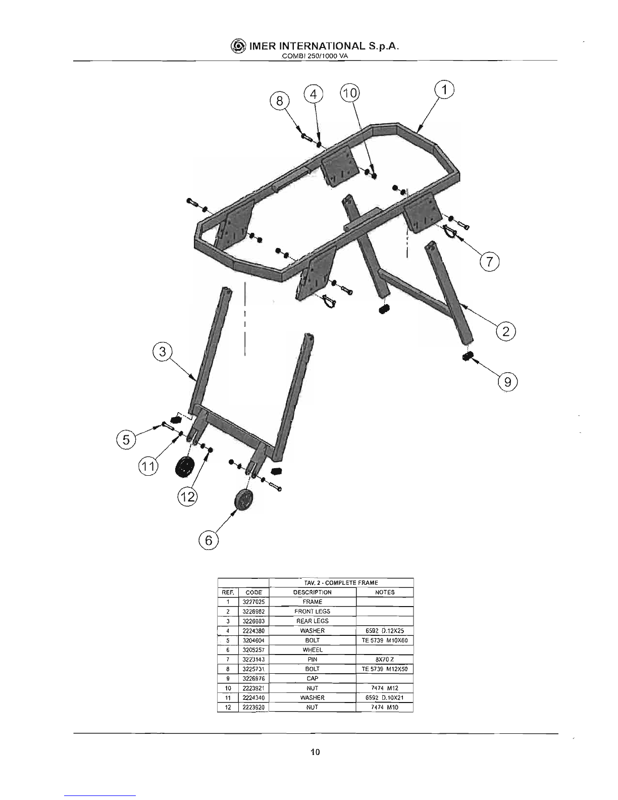
6
TAV.
2.
COMPLETE
FRAME
REF.
CODE
DESCRIPTION
NOTES
1 3221025
FRAME
2 3226982
FRONT
LEGS
3 3226903
REAR
LEGS
4 2224380
WASHER
6592 D.12X25
5 3204604
BOLT
TE
5739
M10X60
6 3205257
WHEEL
7 3223143
PIN
8X70Z
8 3225731
BOLT
TE
5739
M12>(50
9 3226976
CAP
10
2223921
NUT
7474
M12
11
2224340
WASHER
6592 D.l0X21
12
2223920
NUT
7474
M10
10
~
IMER INTERNATIONAL S.p.A.
COMBI
250/1POO
VA
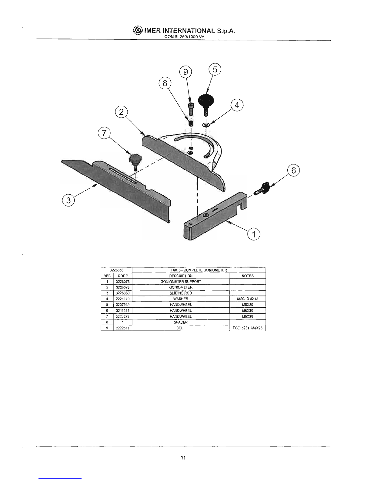
6
3226358
TAV.
3·
COMPLETE
GONIOMETER
REF.
CODE
DESCRIPTION
NOTES
1
3226076
GONIOMETER
SUPPORT
2
3226078
GONIOMETER
3
3226360
SLIDING
ROD
4
2224140
WASHER
6593
D8X18
5
3207939
HANDWHEEL
M,8X30
6
3211381
HANDWHEEL
M8X30
7
3223279
HANDWHEEL
M6X20
8
SPACER
9
2222511
BOLT
TCEI5931
M8X25
11
~
IMER INTERNATIONAL S.p.A.
COMB
I
250/1000
VA
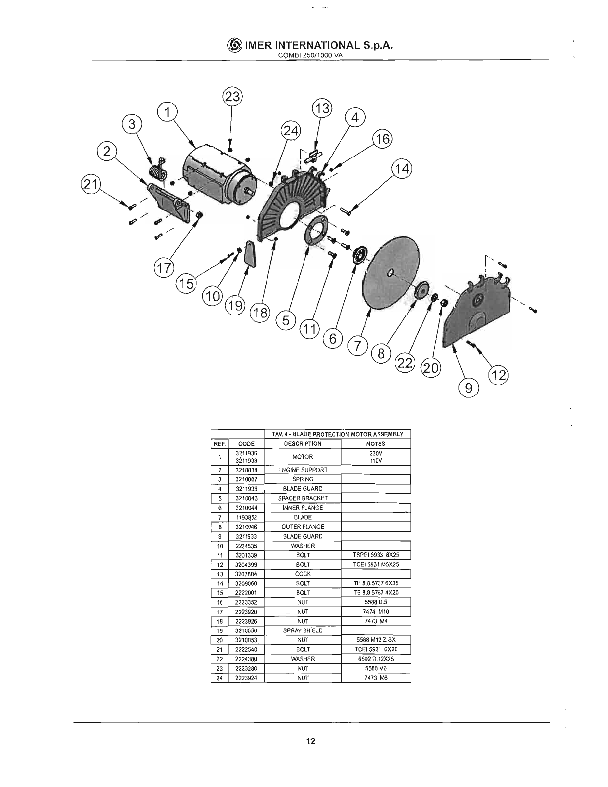
.-
TAV.
4·
BLADE
PROTECTION
MOTOR
ASSEMBLY
I
REF.
CODE
DESCRIPTION
NOTES
! 1
I
3211936
3211936
MOTOR
230V
110V
2
3210038
ENGINE
SUPPORT
3
3210067
SPRING
4
3211935
BLADE
GUARD
5
3210043
SPACER
BRACKET
6
3210044
INNER
FLANGE
7
1193852
BLADE
8
3210046
OUTER
FLANGE
9
3211933
BLADE
GUARD
10
2224535
WASflER
11
3201339
BOLT
TSPEI
5933
8X25
:
12
3204399
BOLT
TCEI
5931
M5X25
13
3207884
COCK
14
3209060
BOLT
TE
8.85737
6)(35
15
2222001
BOLT
TE
6.8
5737
4X20
16
2223352
NUT
55880.5
17
222.3920
NUT
7474
M10
18
2223926
NUT
7473
M4
19
3211)050
SPRAY
SHiELD
20
32100s;j
NUT
5588
M12
ZSX
21
2222540
BOLT
TCEI
5931
6X20
?2
2224380
WASHER
6592D.12X25
23
2223280
NUT
5588
M6
24
2223924
NUT
7473
M6
12
ERNATIONAA~LS~.P=.A~_.
_
~
IMER
1~~Elr250/1000VA_
M20x1.5
SWITCH
230V
CAPACITO'RR~
__
+-
__
ilf<,O~V:--_
23QV
C
TRIC
PANEL
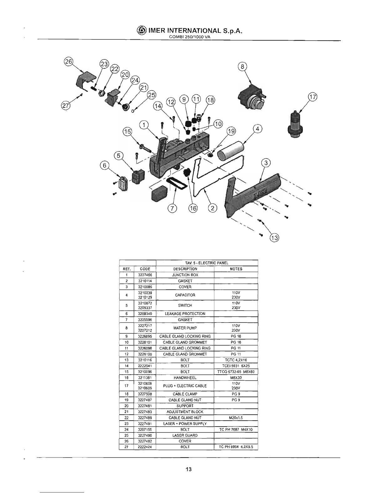
TAV,
5•
ELE
NOTES
DESCRIPTION
JUNCTION
BOX
GASKET
COVER
110V
CABLE
GLAND
NUT
BOLT
COVER
ADJUSTMENT
BLOCK
230V
PLUG
+
ELECTRIC
CABLE
PG
9
CABLE
CLAMP
PG
9
CABLE
GLAND
NUT
SUPPORT
L==--+-;;;;:;;:;;;;Ql
...
t~lA~S~ER~+~POgW~E~R~S~U~P~P~LY=+=T~C
PH
7687
M4Xl0
BOLT
LASERGLJARD
~~~~!P~RgOTE~c~T~rO~Nc...-t===;:;==_
L
-'-:_~~~IT-'
!I:5E=A=KA~~t==_t-
__
~~
__
~J
-
~-l-~~;;;r
GASKET
,'OV
230V
WATER
PUMP
PG
16
NO
LOCKING
RIN.:.-G=-....__
PG
'6
CABLE
GlA 0
GROMMET,_-"-_
PG
11
CABLE~:
LOCKING
RI~N~G-.L-_-7;;PG~'
'--:J
CABLE
G
ND
GROMMET
TeTC
4,2X16
·.12.-+-7.=~;;;;-1
CABLE~G=lA~t===---+
__
~~~~~;o
-
BOLT
TCEI5931
6X25
-
===--~BgOI~.T:--
__
=Dn~cQ
5732.65
M8X60
-2.::~~:;;;;;:<:i1-1
BOLT
M6X30
HANDWHEEL
"OV
13

~
IMER
INTERNATIONAL S.p.A.
COMBI
250/1000
VA
LASER
r-
-.,
I I
I I
I I
I I
I I
I I
I I
I I
L
oJ
I
~--
I
I
I
J
I
I
I
I
I
I
I
I
I
c
__
C1
-----.,
I
I
I
I
I
r-----,-----.,
I II
: I
~--
ro-
I I I I
I I I I
I
--'--
I I
I
--
I I
I I I
I 1 I
__
J I
L
~
I
L1
N PE
WIRING
DIAGRAM
REF,
DESCRIPTION
NOTES
81
CONTROL
SWITCH
C1
CAPACITOR
PE
EARTHING
CABLE
N
NEUTRAL
LINE
CABLE
11
PHASE
LINE
CONDUCTOR
M1
~LADEMOTOR
M2
PUMP
MOTOR
ID
CURRENT
CIRCUIT
BREAKER
KIT
230V
COD,1169245
KIT
110V
COD.
1169249
TR1
POWER
S.UPPI.Y
D1
LASER
EMITIER
14
(;@
IMER INTERNATIONAL S.p.A.
COMBI
250/1000
VA
,
11
~,.~.
~
~
"
I
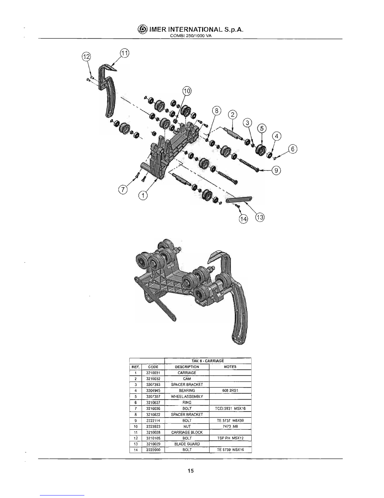
TIW.
6·
CARRIAGE
j
REF.
CODE
DESCRIPTION
NOTES
1
3210031
CARRIAGE
2
3210032
CAM
3
3207393
SPACER
BRACKET
4
3204945
BEARING
6082RS1
5
3207397
'NHEELASSEMBLY
6
3210627
RING
7
3210036
BOLT
TCEL5931
M5Xl6
8
3210622
SPACER
BRACKET
9
2222114
BOLT
TE
5737
M8X90
10
2223923
NUT
7473
M8
11
3210028
CARR)AGE
BLOCK
12
3210105.
BOLT
TSP
PH
M5X12
13
3210029
BLADE
GUARD
14
2222000
BOLT
TE
5739
M5X16
15

~
IMER INTERNATIONAL S.p.A.
COMBI 250/1000 VA
FIG.
6
COD.1188176
TAV.
7·
SIDE
ROLLER
REF.
CODE
DESCRIPTION
NOTES
1
3226953
SUPPORT
2
3226146
SUPPORT
3
3226145
SUPPORT
4
'-.--
....
3226952
SIDE
ROLLER
16
®IMER INTERNATIONAL S.p.A.
COMBI250/1000
VA
ONE YEAR WARRANTY
We
warrant
to
the original purchaser that the IMER equipment described herein (the "equi-
pment") shall
be
free from defects
in
material and workmanship under normal use and
service for which it was intended for a period
of
one (1) yearfrom the date of purchase by
the original purchaser.
Our obbligation under this warranty
is
expressely limited to replacing or repairing, free of
charge, F.O.B. our designated service facility, such part or parts
of
the equipment
as
our
inspection shall disclose
to
be defective. Parts such as engines, motors, pumps, valves,
electric motors, etc. furnished by us but not manifactured by us will carry only the warranty
of the manifacturer. Transportation charges
or
duties shall be borne by the purchaser. This
shall
be
the limit
of
our liability with respect
to
the quality of the equipment.
This warranty shall not apply to any equipment, or parts thereof, which has been damaged
by reason of accident, negligence, unreasonable use, faUlty repairs,
or
which has not been
mantained and operated
in
accordance with our printed instructions for our equipment.
Further, this warranty
is
void if the equipment, or any of its components,
is
altered or modi-
fied
in
any way.
THIS WARRANTY
IS
EXPRESSLY
IN
LIEU OF ALL OTHER WARRANTIES, EXPRES-
SED OR IMPLIED, INCLUDING ANY IMPLIED WARRANTY OF MERCHANTABILITY OF
FITNESS FOR A PARTICULAR PURPOSE.
We make
no
other warranty, representation or guarantee, nor is anyone authorized
to
make one
on
our behalf. We shall not be liable for any consequential damage of any kind,
including loss or damage resulting, directly or indirectly, from the use or loss of use of the
machine. Without limiting the generality
of
the foregoing, this exclusion from liability em-
braces the purchase's expenses for downtime, damages for which the purchaser may
be
liable
to
other persons, damages to property,
and
injury or death
of
any persons.
This warranty shall not be deemed
to
cover maintenance parts, inclUding but not limited
to
blades, belts, hoses, hydraulic oil or filters, for which we shall have
no
responsability or
liability whatsoever.
IMER U.S.A. Inc.
221
Westhampton Place
Capitol Heights, MD 20743
Ph. 301.336.3700
Fax 301.336.6687
Toll
Free: 800.275.5463
www.imerusa.com
17


---
--------------
-
---
-------
----
----
._._----------
COJl1BT
25G-l000
)
/0
Va
L T
13
2.3
23
13
I J
,
Pow~R.
P~MP
/1
()
TO
R
1/1
SWL
Ie!. H

This is a contact addendum to our manuals
Imer USA East
221 Westhampton Pl
Capitol Heights, MD 20743
Phone: 301-336-3700
Fax: 301-336-6687
Order Fax:301-336-5811
Imer USA West
3654 Enterprise Ave
Hayward, CA 94545
www.imerusa.com
800-275-5463
Other IMER Saw manuals


