Page 7
200 Series 36V 15312
7. Install and tighten jackshaft nut until there is no horizontal play in the
pulleys (approx. 90 –110 ft-lbs).
8. Tension the belt following the instructions found in Section 4 -Belt
Tensioning.
9. Replace guard removed in step 1.
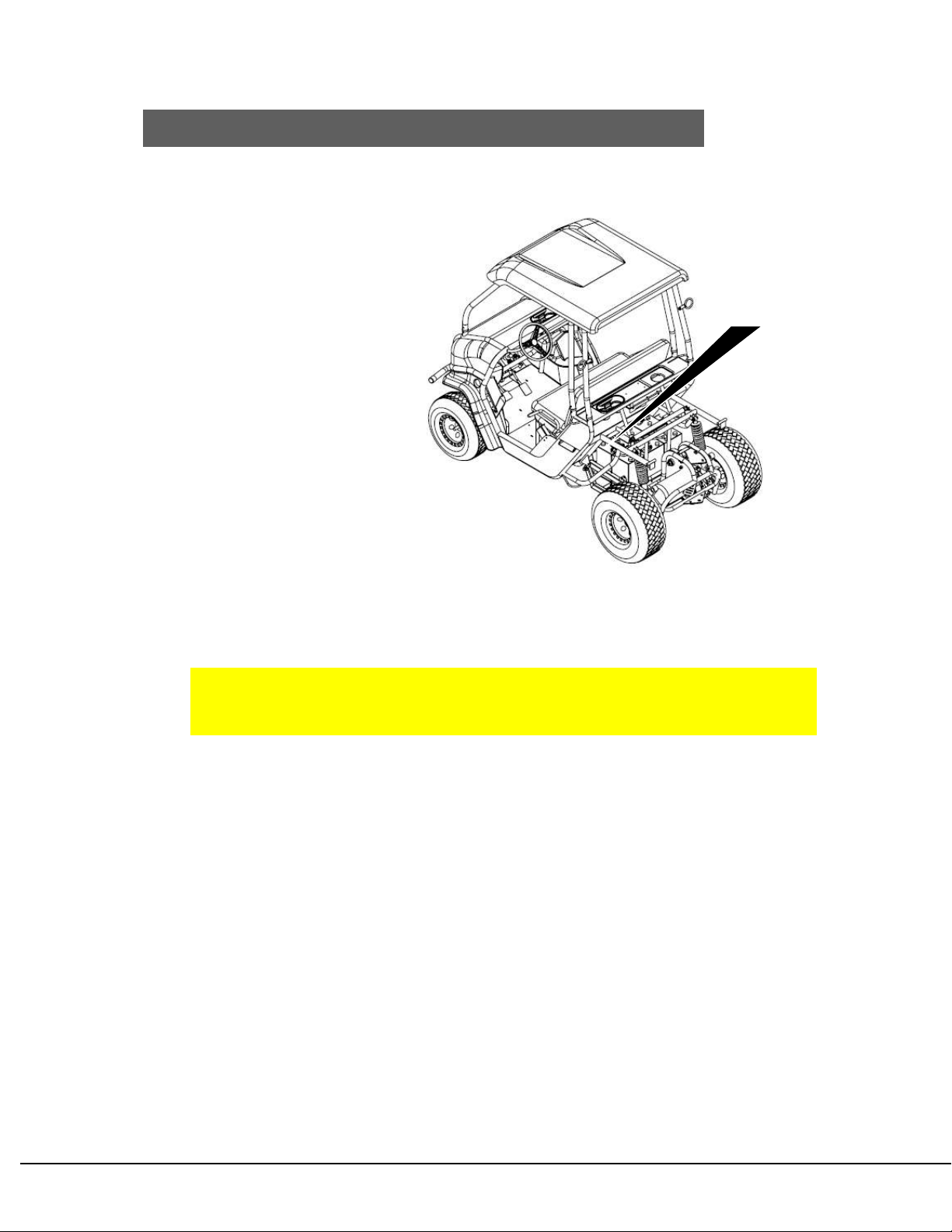
Secondary Belt Replacement
Secondary belt replacement requires disassembly of the jackshaft components.
When attempting to loosen or tighten jackshaft nuts, stay clear of all belt-driven
components, as they may rotate during this process.
1. Jack the vehicle’s swingarm and place on jack stands to keep the rear wheels
off the ground. Do NOT use the Axle as a jack point.
2. Remove left rear tire/wheel
3. Remove the guard above the pulleys.
4. Loosen the secondary belt tensioner’s smaller 3/8” bolt.
5. Loosen left rear axle bearing flange and slide bearing assembly to the left.
6. Remove the right jackshaft nut.
7. Slide the jackshaft to the left until the wide pulley is free to be removed.
8. Remove secondary drive belt by sliding it off of its pulley, down the axle
shaft to the left, through the slot of the swingarm axle bracket, and then off
the axle.
9. Install the new belt by sliding it over the axle, through the slot of the
swingarm axle bracket, and placing it over the axle pulley.
10.Place loose pulley inside the belt.
11.Line up pulley with keyway on the jackshaft and slide the jackshaft right,
through the spacer and bearing.
12.Install and tighten jackshaft nut until there is no horizontal play in the
pulleys (approx. 90 –110 ft-lbs).
13.Replace guard removed in step 3.
14.Tension the belt following the instructions found in Section 4 -Belt
Tensioning.
15.Reinstall the left rear tire/wheel.
16.Raise vehicle slightly and remove jack stands and lower vehicle.
Section 5 -THROTTLE
Proper installation and adjustment of the throttle assembly will ensure safe and
reliable control. Improper adjustment could result in undesirable results, such as a
sticking throttle pedal or lack of functionality. Follow the instructions below.
THROTTLE INSTALLATION AND ADJUSTMENT
Before working on the throttle assembly, ensure the key switch is in the OFF
position.