ClipperCreek HCS User manual

ClipperCreek, Inc.
Innovative Infrastructure for
Electric and Hybrid Vehicles
• • • • • • •
Model HCS
User’s Manual

HCS User’s Manual
PLEASE NOTE
This user’s manual includes the latest information at the time of printing.
ClipperCreek, Inc. reserves the right to make changes to this product without
representative. Refer to the Customer Support section located in this guide.
All rights reserved. Printed in the USA.
Please visit ClipperCreek’s Website @ www.clippercreek.com

HCS User’s Manual
CONTENTS
IMPORTANT SAFETY INSTRUCTIONS.....................................5
ADDITIONAL SAFETY INFORMATION ....................................7
FCC INFORMATION .....................................................................8
OPERATION ...................................................................................8
THE HCS FRONT PANEL..............................................................
INSTALLATION ...........................................................................10
SERVICE CONNECTIONS ..........................................................10
MOUNTING PROCEDURES.......................................................14
MOUNTING THE CONNECTOR HOLSTER.........................17
WIRING INSTRUCTIONS (Hardwired HCS) .............................18
RECEPTACLE INSTRUCTIONS (Plug-in HCS-P)..................
CHARGE CABLE WRAP GUIDELINES....................................
GROUNDING INSTRUCTIONS .................................................
MOVING & STORAGE INSTRUCTIONS.................................
CHARGEGUARDTM ENABLED HCS INSTRUCTIONS ..........
TM ENABLED HCS INSTRUCTIONS..........................
MAINTENANCE .........................................................................
CUSTOMER SUPPORT ..............................................................
SPECIFICATIONS ........................................................................
WARRANTY INFORMATION (3 Year Standard) ...................... 30
WARRANTY INFORMATION (5 Year Ruggedized) ................. 31

HCS User’s Manual
Page 4
This page was left intentionally blank.
HCS User’s Manual
Page 5
IMPORTANT SAFETY INSTRUCTIONS
charge station:
This means pay particular attention. Notes contain helpful suggestions.
Cela signie accorder une attention particulière.
contiennent des suggestions utiles.
CAUTION: This symbol means be careful.
ATTENTION: Ce symbole signie être prudent.
WARNING: This symbol means danger. You are in a situation
and standard practices for preventing accidents.
AVERTISSEMENT: Ce symbole signie un danger. Vous êtes dans
Instructions Pertaining to a Risk of Fire or Electric Shock
SAE-J1772TM charge port only. Consult the vehicle owner’s manual to
• Make certain the charge station SAE-J1772TM
damage or stress.
Support section in this manual for service information. Do not attempt
SAE-J1772TM charge
the Customer Support section in this manual for information on the
NOTE

HCS User’s Manual
• Not for use in commercial garages where a COMMERCIAL GARAGE
• SAE-J1772TM charge
•
Instructions se Rapportant à un Risque d’Incendie ou de Choc
Électrique
doivent être suivies:
•
SAE-J1772TM port de recharge seulement. Consultez le manuel
correcte port de recharge.
• SAE-J1772TM
•
vous-même.
•
•
• SAE-J1772TM
• Ne pas laisser les enfants utiliser cet appareil. Supervision d’un adulte est

HCS User’s Manual
Page 7
ADDITIONAL SAFETY INFORMATION
WARNING:
AVERTISSEMENT:
l’appareil.
when charging indoors. Consult the vehicle owner’s manual to
Vehicles which conform to the SAE-J1772TM standard for
SAE-J1772TM de
CAUTION: DO NOT CHARGE
ATTENTION: NE PAS RECHARGER
plus d’informations.
Save these instructions for future reference.
Conservez ces instructions pour référence future.
NOTE
NOTE

HCS User’s Manual
Page 8
FCC INFORMATION
(RFI). However there are some instances where high powered radio signals or
for assistance:
1.
charging.
CAUTION
ATTENTION:
OPERATION
The HCS Electric Vehicle Charging Station is a compact wall or pedestal-
Vehicle (together Plug-In Electric Vehicles, or “PEV”) user with a safe and
SAE-J1772TM
When the vehicle has stopped charging the green “Charging” light on the HCS
(or to interrupt a charge in progress) press and hold down the latch release lever
on the charge coupler handle then unplug the charge coupler from the vehicle
charge port.
HCS User’s Manual
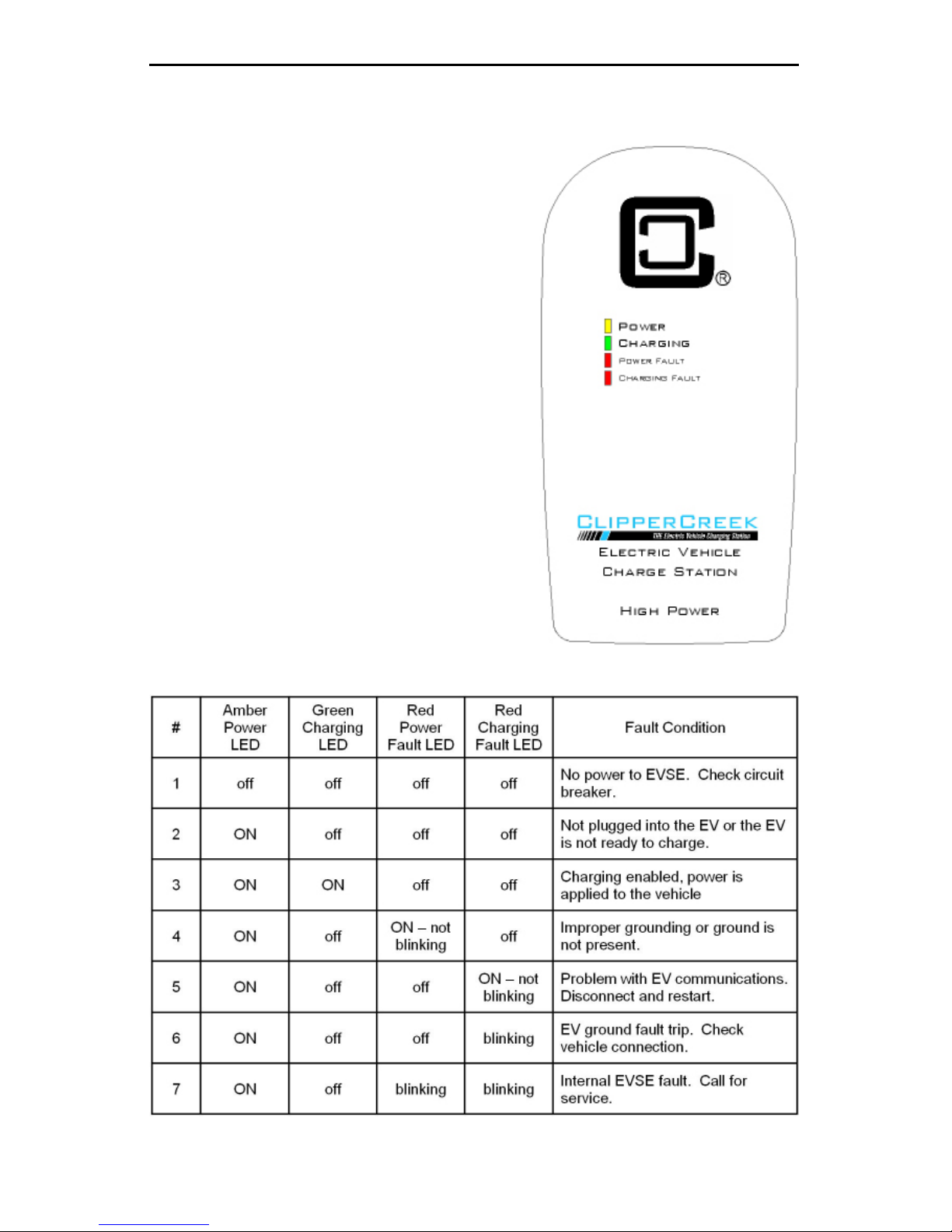
THE HCS FRONT PANEL
Figure 1. Front Panel
The front panel on the HCS has four indicator
lights, as shown in Figure 1:
POWER
CHARGING (green), indicates that the
POWER FAULT (red), indicates that the HCS
due to improper grounding or a missing Earth
CHARGING FAULT (red), indicates that the
Table 1. Front Panel LED Information
HCS User’s Manual
Page 10
INSTALLATION
SERVICE CONNECTIONS
CAUTION: -
in accordance with the National Electrical Code, ANSI/NFPA 70 (US) or
ATTENTION:
-
CAUTION: This is a single-phase device. Do not connect all three
phases of a 3-phase feed !!!
ATTENTION: Il s’agit d’un appareil monophasé. Ne pas relier tous
les trois phases d’une alimentation triphasée!!! Vous pouvez utiliser
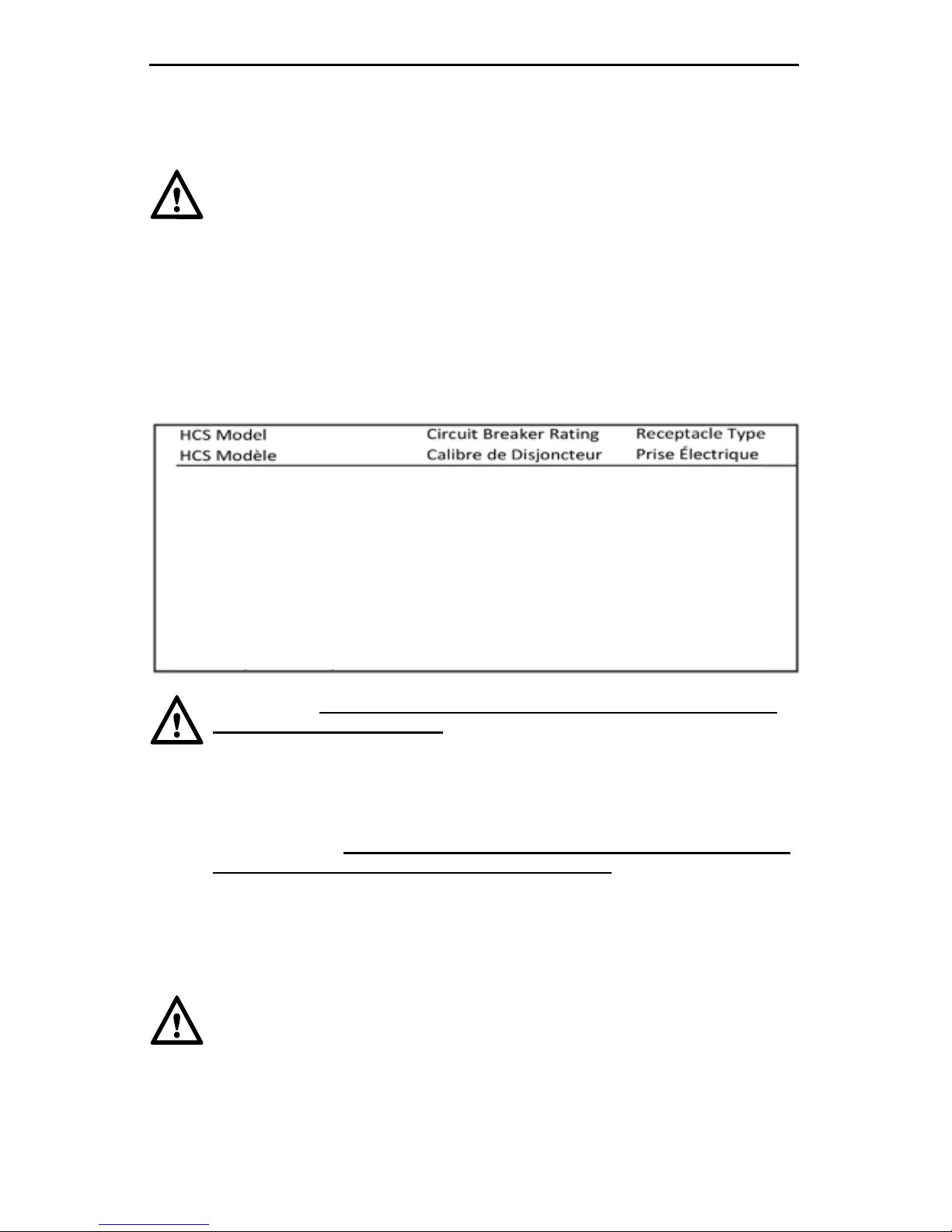
CAUTION
ATTENTION
HCS-15 (Hardwired) 15A n/a
HCS-25 (Hardwired) 25A n/a
HCS-30 (Hardwired) 30A n/a
HCS-40 (Hardwired) 40A n/a
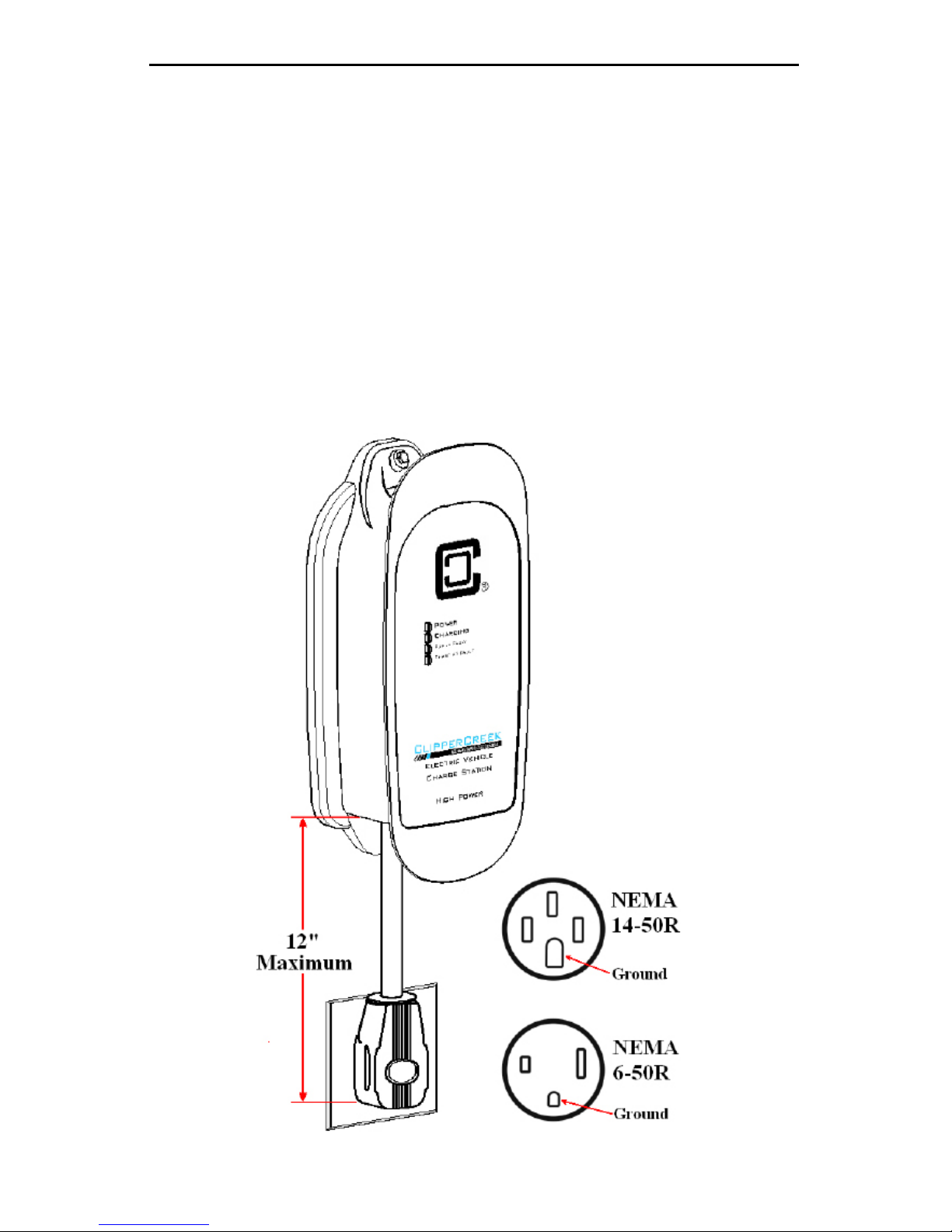
HCS-40P + NEMA 6-50P 50A NEMA 6-50R
HCS-40P + NEMA 14-50P 50A NEMA 14-50R
HCS-50 (Hardwired) 50A n/a
HCS-50P + NEMA 6-50P 50A NEMA 6-50R
HCS-50P + NEMA 14-50P 50A NEMA 14-50R
HCS-60 (Hardwired) 60A n/a

HCS User’s Manual
Page 11
CAUTION
Grounded
ATTENTION
tap. Que la tap doit être
ci-dessous.
CAUTION: Warranty is void if this unit is not wired properly
ATTENTION: La garantie est annulée si cette unité n’est pas
correctement câblé
WARNING
electrical codes and ordinances.
AVERTISSEMENT
known, and the 3 wires from the main circuit
outputs correspond to the same inputs on the HCS. Also, each of the two
3-phase diagrams shows an L3 output, which is not used. Do not connect all
The Neutral at the service panel mustsomewhere
any of the three connection arrangements. Ground-fault
point.
WARNING
installing the grounding stake.
AVERTISSEMENT
HCS User’s Manual
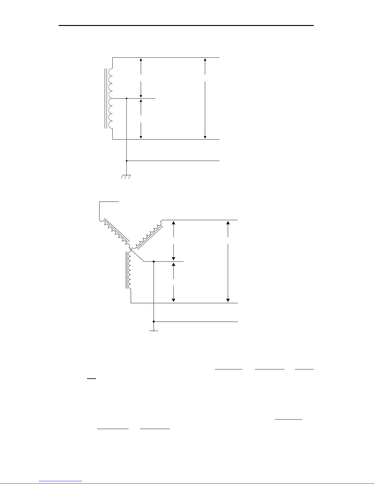
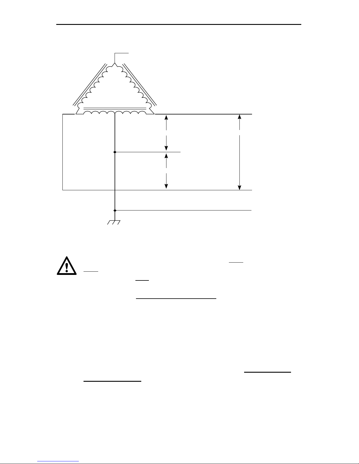
Figure 3 - 208V 3-Phase, Wye-Connected
L3 (NOT USED)
L2
L1
GROUND
NEUTRAL
(NOT USED)
120V208V
120V
connections most common in North America.
, or L1 & L3, or
L3
Ground. Be sure the center point is grounded to Earth somewhere in the
,
ou L1 & L3, ou
NOTE
L1
L2
NEUTRAL
120V
120V
GROUND
(NOT USED)
240V
Figure 2 - 220/240V Single Phase
HCS User’s Manual
Page 13
CAUTION: With the delta connection, one leg must
Only
two phases must both
to as a “stinger”. Do not use this third line! Consult the transformer
ATTENTION:
Ne pas utiliser
ce troisième ligne! Consultez la documentation du transformateur
Figure 4 - 240V 3-Phase, Delta-Connected, with center-tap on one leg
120V
120V
240V
NEUTRAL
(NOT USED)
L1
L2
GROUND
L3 (DO NOT USE!)
HCS User’s Manual
Page 14
MOUNTING PROCEDURES
Locate the wall mounting position of the EVSE:
mounted NEMA socket.
for outdoor installations. Ensure that the LEDs on the front panel of the
locations on the mounting surface.
WARNING:
unplugging it or disconnecting the unit from the service lines.
AVERTISSEMENT:
partir des lignes de services.
CAUTION:
a center-tap on one leg cannot be used with the HCS. No “Neutral”
The HCS will not allow the contactor to close if it does not sense the
presence of a Ground wire connected to a “Neutral” point on the
ATTENTION:
secondaire sans centre-tap sur le terminal
avec la HCS
transformateur.
HCS User’s Manual
Page 15
FOR HOLLOW-WALL CONSTRUCTION
•
structural framing inside of the wall or a strong wall surface such as
•
to grip the wooden structure while preventing the wood from cracking or
splintering while the screw is fastened.
•
screw head.
•
of the lag screw.
• If either mounting hole does not have a solid mounting structure (such
Figure 5. Mounting the HCS to a hollow wall
Figure 5. Mounting the HCS to a hollow wall

HCS User’s Manual
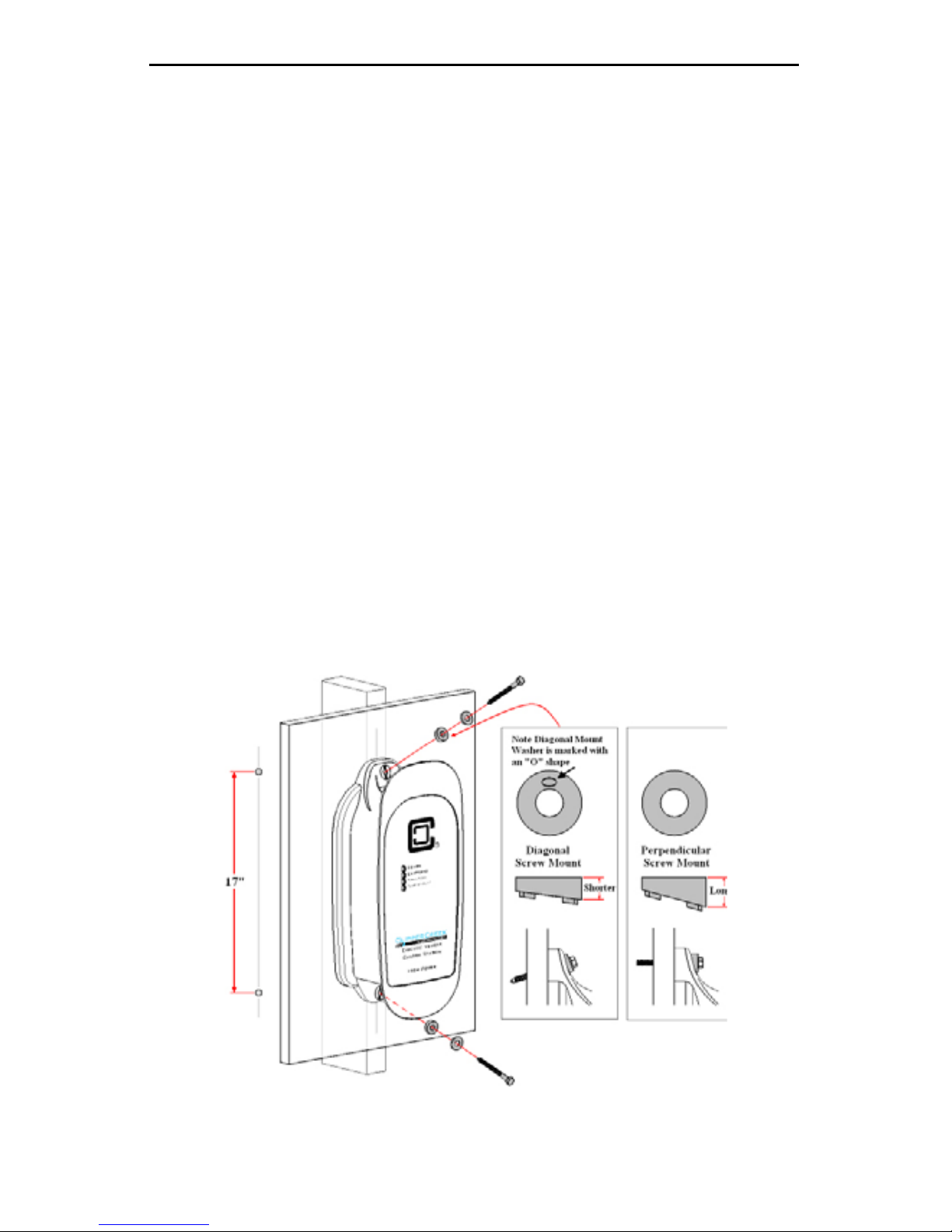
FOR SOLID-WALL CONSTRUCTION
•
•
•
fastened either at an angle or perpendicular to the mounting surface. Note
there are two different sets of plastic angle washers included. Select those
accomodate the mounting hardware “angle of attack” and
•
•
Figure 6. Mounting the HCS to a solid wall
HCS User’s Manual
Page 17
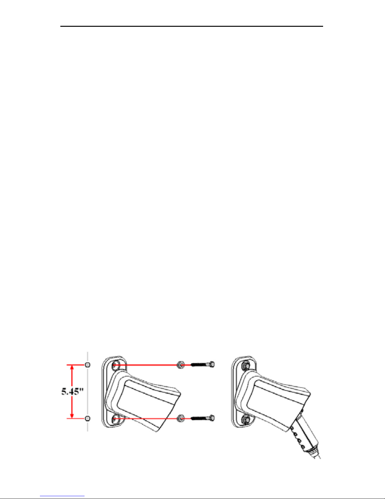
MOUNTING THE SAE-J1772TM
CONNECTOR HOLSTER
The SAE-J1772TM connector holster is included to provide a convenient
TM connector head when it is not in use.
• The SAE-J1772TM
SAE-J1772TM connector.
• For indoor installation, mount the SAE-J1772TM
• For outdoor installation, mount the SAE-J1772TM
• The SAE-J1772TM
ruler or template to mark hole locations on the mounting surface.
• The vertical alignment of the HCS and SAE-J1772TM connector holster
• Place the SAE-J1772TM
take advantage of solid structural framing inside of the wall or a strong wall
•
the purposes of mounting the SAE-J1772TM connector holster to a wooden
surface.
•
of mounting hardware most appropriate for the supporting structure.
Figure 7. Mounting the holster using the exterior wood screws and washers
HCS User’s Manual
Page 18
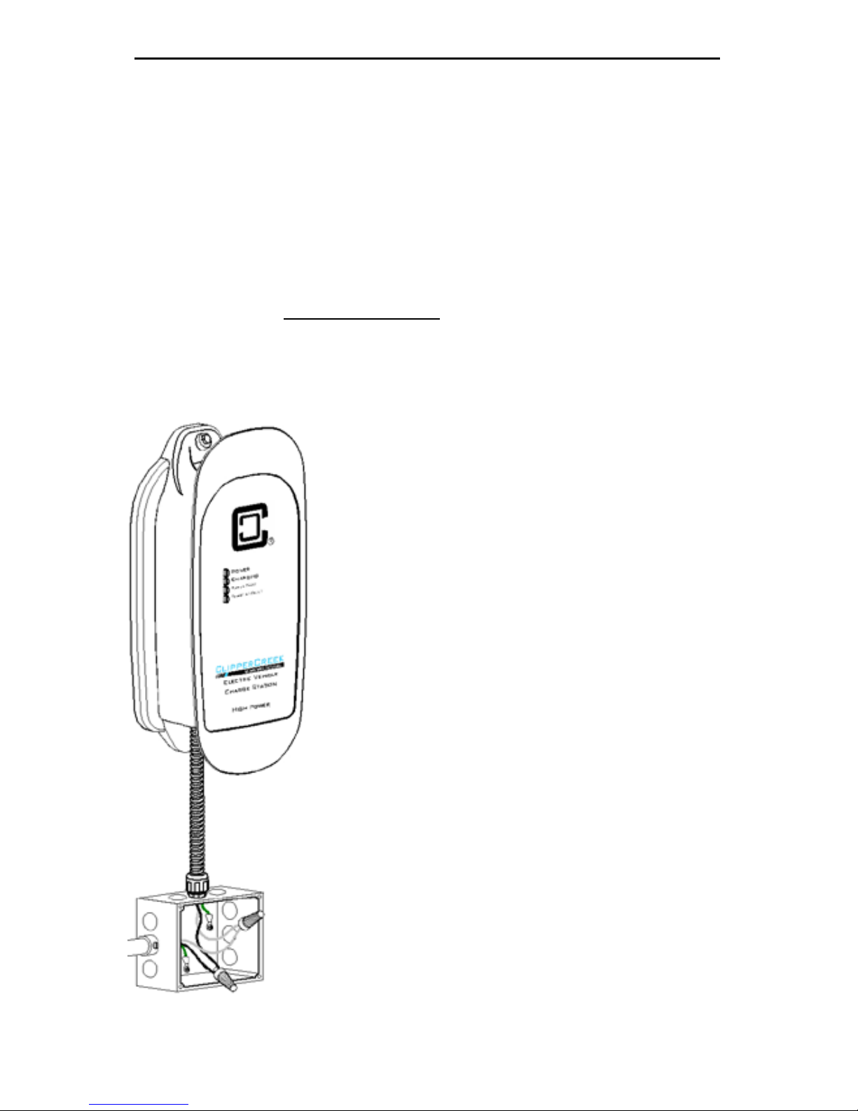
WIRING INSTRUCTIONS
(Hardwired HCS)
-
of this manual titled Service Connections
Figure 8. Wiring the HCS in a junction box
service conductors use stranded 10 AWG 75ºC copper
conductors use stranded 8 AWG, 75ºC copper wire.
The insulation of each conductor is color coded for
Green: Ground
10 AWG 75ºC.
75ºC.
HCS User’s Manual
RECEPTACLE INSTRUCTIONS
(Plug-In HCS-P)
of it.
furthest point on the plug. With this in mind, it is recommended that a NEMA
socket is at the lowest point.
Figure 9. Preferred orientation of the NEMA receptacles below the HCS-P
HCS User’s Manual
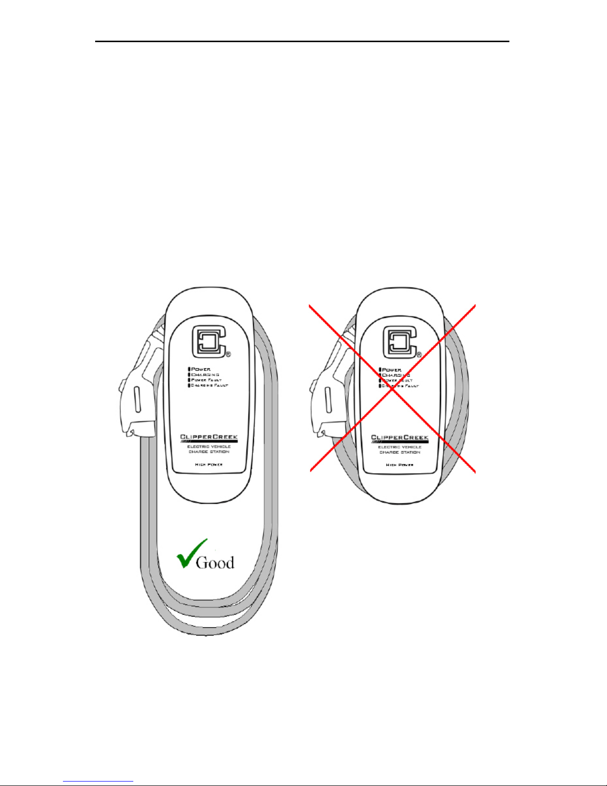
CHARGE CABLE WRAP GUIDELINES
case.
reach is desired.
Figure 10. Drape the charge cable loosely around the HCS enclosure
Other manuals for HCS
2
Table of contents
Popular Golf Car manuals by other brands

Cushman
Cushman Hauler 800X Elite 2022 owner's manual

American Landmaster
American Landmaster 36V 200 Series Service manual

Cricket
Cricket Grasshopper Owner's manual, safety guide, and warranty information

Ransomes
Ransomes diabline Operation & service manual

I-Motioncaddys
I-Motioncaddys im4 Range 2013 manual

Ezgo
Ezgo RXV EX1 EFI owner's manual

ELLWEE
ELLWEE EGC 201801 Series manual

Peg-Perego
Peg-Perego POLARIS Use and care guide

CRICKET MINI GOLF CARTS
CRICKET MINI GOLF CARTS RX5 owner's manual

Rollplay
Rollplay W461-C04 Owner's manual and assembly instructions

Arctic Cat
Arctic Cat Prowler Operator's manual

Regal Research
Regal Research SoloRider Operator's manual


