American Sanders 07104A User manual

Electronic Service
Manuals
This electronic document is provided as a service to our customers.
Wedonotcreatethecontentsoftheinformationcontainedinthisdocu-
ment. Shouldyouhavedetailedquestionspertainingtotheinformation
contained in this document, you may contact Michco, or the manufac-
turer which provided the original information in this electronic deliver-
able. Michco’sonlypartin this electronic deliverable was the electronic
assemblyprocess. Byprovidingthismanualonlinewearenotguaran-
teeing parts availability.
You may contact Michco through the following methods:
Phone (517) 484-9312 or (800) 331-3339
2011 N. High St. -- Lansing, Michigan -- 48906
Fax: (517) 484-9836
Email: [email protected]
Web site: www.Michco.Com
Parts Web site: www.FloorMachineParts.Com
Order Parts on Line at:
www.FloorMachineParts.Com
Directly to Parts & Service:
By Fax: (517) 702-2041
By Voice: Use numbers above.
Serving the Cleaning Industry Since 1922
Notice: All copyrighted material remains property of original owners, all trademarks are property of respective owners.
ManualsaresubjecttoManufacturer’sreproductionlimitations. Originalsorreproductionswereprovidedbymanufacturers
through a request. We make no warranty as to the correctness of information provided in this document and you assume
allrisk. By placing thesemanualsonlinewe are notdeclaringourcorporation to be anmanufacturerauthorizeddealer or
provider, please check ourwebsiteforauthorizedmanufacturerswerepresent.

Form No. 70255B 7/08 revised 10/10
FloorCrafter
Belt Sander
U.S. Patent No. 5,575,710 and No. 6,578,858
Operator's Manual / Manual del operador / Manuel de l’utilisateur
Models: 07104A, 07111A, 07117A, 56380917
This book has important information for the use and safe operation of this machine. Failure to read this book prior to
operating or attempting any service or maintenance procedure to your Clarke American Sanders machine could result
in injury to you or to other personnel; damage to the machine or to other property could occur as well. You must have
training in the operation of this machine before using it. If your operator(s) cannot read this manual, have it explained
fully before attempting to operate this machine.
All directions given in this book are as seen from the operator’s position at the rear of the machine.
English (2 - 20)
Español (22 - 40)
Français (42 - 60)
READ THIS BOOK
LEA ESTE MANUAL
LISEZ CE MANUEL
ES
EN
FR

EN
ENGLISH
-2- FORM NO. 70255B Clarke®American Sanders Operator's Manual (EN) - Floorcrafter
Table of Contents
Operator Safety Instructions........................................................................................................ 3
Introduction and Machine Specifications..................................................................................... 5
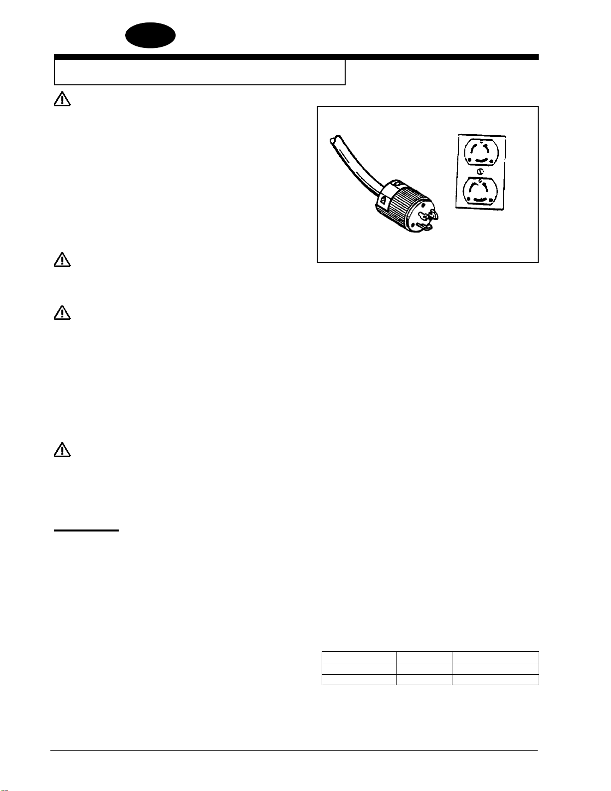
230V Electrical Connection Instructions...................................................................................... 6
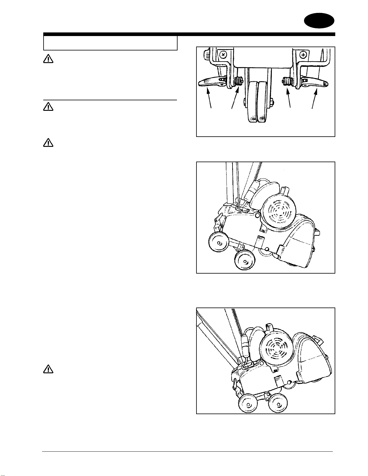
How to Transport the Machine..................................................................................................... 7
One Person............................................................................................................................ 8
Two People ............................................................................................................................ 9
Machine Set-Up........................................................................................................................... 9
How to Operate the Machine......................................................................................................11
Sanding Cuts and Sandpaper ................................................................................................... 13
Chatter Wave Prevention .......................................................................................................... 14
Sander Adjustment Procedures................................................................................................. 15
Dust Shoe.............................................................................................................................. 15
Sanding Pressure.................................................................................................................. 15
Leveling the Drum ................................................................................................................ 15
Belt Tracking.......................................................................................................................... 16
Operating Control .................................................................................................................. 16
Routine Maintenance................................................................................................................. 17
Sanding Chamber.................................................................................................................. 17
Wheels................................................................................................................................... 17
Dust Bag................................................................................................................................ 17
Drive Belt............................................................................................................................... 17
Bearings ................................................................................................................................ 18
Rollers ................................................................................................................................... 18
Troubleshooting......................................................................................................................... 19
SECTION II Parts and Service Manual
Main Assembly Drawing #1.......................................................................................................62
Main Assembly Parts List #1................................................................................................ 63
Handle Control Assembly Drawing #2...................................................................................... 64
Handle Control Assembly Parts #2....................................................................................... 65
Contact Wheel & Truck Assembly Drawing #3 .......................................................................... 66
Contact Wheel & Truck Assembly Parts List #3................................................................... 67
Belt Tensioner Assembly Drawing #4 ........................................................................................ 68
Belt Tensioner Assembly Parts List #4 ................................................................................. 69
Dolly Assembly Drawing & Parts List #5.................................................................................... 70
Motor Assembly & Parts List #6.................................................................................................71
Wiring Diagram.......................................................................................................................... 72
WARNING!
The Products sold with this Manual contain or may contain chemicals that are known to certain governments (such as the State of
California, as identified in its Proposition 65 Regulatory Warning Law) to cause cancer, birth defects or other reproductive harm. In
certain locations (including the State of California) purchasers of these Products that place them in service at an employment job site or
a publicly accessible space are required by regulation to make certain notices, warnings or disclosures regarding the chemicals that are
or may be contained in the Products at or about such work sites. It is the purchaser’s responsibility to know the content of, and to comply
with, any laws and regulations relating to the use of these Products in such environments. The Manufacturer disclaims any responsibility
to advise purchasers of any specific requirements that may be applicable to the use of the Products in such environments.

EN
ENGLISH
Clarke®American Sanders Operator's Manual (EN) - Floorcrafter FORM NO. 70255B - 3 -
OPERATOR SAFETY INSTRUCTIONS
WARNING AVERTISSEMENT ADVERTENCIA
DANGER means: Severe bodily injury or death can occur to you or other personnel if the DANGER statements
found on this machine or in this Operator’s Manual are ignored or are not adhered to. Read
and observe all DANGER statements found in this Operator’s Manual and on your machine.
WARNING means: Injury can occur to you or to other personnel if the WARNING statements found on your
machine or in this Operator’s Manual are ignored or are not adhered to. Read and observe all
WARNING statements found in this
Operator’s Manual and on your machine.
CAUTION means: Damage can occur to the machine or to other property if the CAUTION statements found
on your machine or in this Operator’s Manual are ignored or are not adhered to. Read and
observe all CAUTION statements found in this Operator’s Manual and on your machine.
DANGER: Failure to read the Operator’s Manual before operating or servicing this sanding equipment could result in
injury to the operator or to bystanders and could cause damage to the equipment. Read and observe all
safety statements found in this manual and on the sanding equipment. Make sure all labels, decals, warn-
ings, cautions and instructions are fastened to the equipment. Replace any that are damaged or missing.
You must have training in the operation of this equipment before using it. If the operator is unable to read
this manual, have it explained fully before they attempt to use this equipment.
DANGER: Sanding/finishing wood floors can create an environment that can be explosive. The following safety proce-
dures must be adhered to:
• Cigarette lighters, pilot lights and any other source of ignition can create an explosion when active during
a sanding session. All sources of ignition should be extinguished or removed entirely if possible from the
work area.
• Work areas that are poorly ventilated can create an explosive environment when certain combustible
materials are in the atmosphere, i.e., solvents, thinners, alcohol, fuels, certain finishes, wood dust and
other combustible materials. Floor sanding equipment can cause flammable material and vapors to burn.
Read the manufacturer’s label on all chemicals used to determine combustibility. Keep the work area well
ventilated.
• Spontaneous combustion or an explosion can occur when working with sanding dust. The sanding dust
can self-ignite and cause injury or damage. Sanding dust should be disposed of properly. Always empty
the sanding dust into a metal container that is located outside of any building(s).
• Remove the contents of the dust bag when the bag is 1/3 full. Remove the contents of the dust bag each
time you finish using the equipment. Never leave a dust bag unattended with sanding dust in it.
• Do not empty the contents of the dust bag into a fire.
• Hitting a nail while sanding can cause sparks and create an explosion or fire. Always use a hammer and
punch to countersink all nails before sanding floors.

EN
ENGLISH
-4- FORM NO. 70255B Clarke®American Sanders Operator's Manual (EN) - Floorcrafter
DANGER: Operating partially assembled sanding equipment could result in injury to the operator or bystander and could
cause damage to the equipment or to other property.
• Do not operate this equipment unless it is fully assembled and all guards, doors and covers are secured.
• Keep all fasteners tight.
• Keep all adjustments within manufacturers specifications.
DANGER: Moving parts on this sanding equipment can cause injury to the operator or bystanders.
• Keep hands, feet and loose clothing away from all moving parts.
• Do not change or adjust the abrasive while the sanding equipment is running.
• Do not service the sanding equipment while it is running.
DANGER: This sanding equipment requires a supply of electricity. Improper use could result in electrical shock or fire.
• Connect only to an electrical source matching what is shown on the equipment nameplate.
• Do not use this sanding equipment on an ungrounded electrical circuit. Consult an electrician if you suspect the
circuit is not properly grounded.
• Do not use this sanding equipment with a damaged electrical cord. Inspect before each use.
• Avoid striking the electrical cord with the abrasive. Always lift the electrical cord over the sanding equipment.
• Do not use the electrical cord to move the sanding equipment.
• Disconnect the electrical source before servicing this equipment.
WARNING: In the event of a bag fire, injury can occur to the operator if the operator is tied or strapped to equipment. Use operat-
ing belt properly (follow procedure on page 11).
WARNING: Injury to the operator or bystander can occur if protective gear is not worn while sanding. Always use eye, ear, and
respiratory protection while performing any sanding operation.
WARNING: Bodily injury could occur if power is applied to the equipment with the power switch already in the “ON” position.
Always check to assure that the power switch is in the “OFF” position before connecting power supply.
CAUTION: Maintenance and repairs performed by unauthorized personnel could result in damage or injury. Maintenance and
repairs performed by unauthorized personnel will void your warranty. Servicing of this unit must always be referred
to an authorized Clarke American Sanders distributor.
CAUTION: Use of this equipment to move other objects or to climb on could result in injury or damage. Do not use this equip-
ment as a step or furniture. Do not ride on this equipment.
CAUTION: Damage could occur to the equipment if not properly kept in a dry building for storage. Store the equipment in a
dry building.
CAUTION: The equipment is heavy. When transporting the equipment, remove the motor. Get help to lift the equipment and
motor.
CAUTION: Serious damage to the floor can occur if the sanding equipment is left running in one spot while the sanding drum
is in contact with the floor. To avoid damage to the floor, feather cut in at a normal sanding rate. Do not dwell while
lowering or raising the contact wheel. Always sand at a constant rate.

EN
ENGLISH
Clarke®American Sanders Operator's Manual (EN) - Floorcrafter FORM NO. 70255B - 5 -
Introduction and Machine Specifications
MODEL 07104A 07111A 07117A 56380917
Electrical 230~, 60Hz 230V~, 50Hz 230V~, 50Hz 230~, 50Hz
Requirements 15.7 A, 3.7 kW 11.8 A, 2.2 kW 12.0 A, 2.2 kW 16.0 A, 3.0 kW
Sound Emisson 93.0 dB(A) 96.2 dB(A) 96.2 dB(A) 96.2 dB(A)
(Lpm)
Vibration <.15 in/s 2.88 m/s2rms 2.88 m/s2rms 2.88 m/s2rms
Motor 4 Hp Induction 2.2 kW Induction 2.2 kW Induction 3 kW Induction
Contact Wheel Rate 2450 rpm 2042 rpm 2042 rpm 2042 rpm
Abrasive Rate 4500 ft/min 3750 ft/min 1143 m/min 3750 ft/min
Abrasive Size 29½” x 77/8” 29½” x 77/8” 750mm x 200mm 29½” x 77/8”
Fan Flow Rate 234 CFM 195 CFM 92 liters/s 195 CFM
Drum Settings 80 lbs., 70lbs., 60 lbs. 80 lbs., 70lbs., 60 lbs. 36 kg, 32 kg, 27 kg 80 lbs., 70lbs., 60 lbs.
Overload Protection Magnetic Circuit Magnetic Circuit 13 A Fuse Magnetic Circuit
Breaker Breaker Breaker
Electrical Cable 50’, 10-3 SJO 100’, 12-3 SJO 15m HO7RN 100’, 12-3 SJO
LP-20P Plug AU2-15P Plug 3 x 1.5mm2AU2-15P Plug
UK1-13P Plug
Operating Controls Adjustable Lever/Grip Adjustable Lever/Grip Adjustable Lever/Grip Adjustable Lever/Grip
Leveling Controls Externally Adjustable Externally Adjustable Externally Adjustable Externally Adjustable
Operating Wheels 80 Durometer 80 Durometer 80 Durometer 80 Durometer
Clear Urethane Clear Urethane Clear Urethane Clear Urethane
Weight 204 lbs. 204 lbs. 94 kg 204 lbs.
Dimensions 35 x 133/4x 383/4 35 x 133/4x 383/4 89cm x 35cm x 98cm 35 x 133/4x 383/4
CAUTION: Your equipment may be inappropriate on some installations. Some softer woods used in floor-
ing cannot support the pressure created by hard wheels.
Always consult with the flooring manufacturer on the proper installation, preparation, and finish-
ing of their product. Determine suitability of your equipment in preparing the product.
revised 10/10

EN
ENGLISH
-6- FORM NO. 70255B Clarke®American Sanders Operator's Manual (EN) - Floorcrafter
Figure 1
230V Electrical Connection Instructions
CAUTION: This machine will operate only on AC fre-
quency and on electrical voltage shown on
the equipment nameplate. Make sure you
have the correct frequency and voltage be-
fore connecting the power cord to an out-
let. See the example in figure 1.
This machine must be connected to an electrical source with an
earthing conductor in order to protect the operator from electric
shock. This machine has an approved power cord with three con-
ductors as well as a plug with three terminals. Connect the plug to
a matching receptacle.
DANGER: Electrocution could occur if the machine
is exposed to water or rain. Keep the ma-
chine in a dry building.
DANGER: Electrocution could occur if machine is not
connected to an electrical source with an
earthing conductor. To prevent possible
electric shock, use an electrical cord with
an earthing conductor and connect it to a
matching electrical source. For maximum
protection against electrical shock, use a
circuit that is protected by a ground fault
circuit interrupter. Consult your electrical
contractor.
DANGER: Electrocution could occur if the machine is
used with a damaged plug or power cord.
If the cords or plugs are worn or damaged
in any way, have them replaced by an au-
thorized service person or electrician.
Extension Cords
Use only an approved three-pronged extension cord with two main
conductors and one earthing conductor. This machine is equipped
with a power cord. When greater range is needed follow the table
below to determine cable gauge of additional footage. Refer to the
chart to the right for extension cord information.
If motor appears to labor or takes a considerable longer time to
come up to speed reduce sanding pressure. Feet/Wire Gauge (Stranded Copper)
Source Voltage 0 - 100’ 100 - 250’
208 6 Use Voltage Booster
230 10 8

EN
ENGLISH
Clarke®American Sanders Operator's Manual (EN) - Floorcrafter FORM NO. 70255B - 7 -
Figure 4
Figure 3
Figure 2
AB BA
How to Transport the Machine
WARNING: The machine is heavy. Remove the motor
from the machine before transporting. Get
help loading the machine and motor. Use
proper lifting techniques.
Transporting the Machine - Using the Dolly Cart
CAUTION: When deploying the dolly, the drum will
contact the floor or ground over which the
machine is resting. Care should be taken
to avoid surfaces which might damage or
contaminate the drum.
CAUTION: While transporting using the dolly, abrupt
changes in the direction of travel or the
surface over which the machine is being
transported could cause the machine to tip
over. Also, the machine is more likely to
tip over when transporting across inclined
surfaces.
Attach the dolly to the rear of the machine as follows:
1. Open the quick release levers (2A) and unscrew the adjustment
nuts (2B) to allow installation of the dolly. (See figure 2)
2. Insert the quick release skewers into the dolly brackets and
immediately tighten the adjustment nuts until the dolly mechanism
will just swing free.
Deploy the dolly under the machine as follows:
1. With the dolly mechanism in place as described above, tip the
machine by lifting up on the operators handle to raise the rear of
the machine off the floor/ground until the dolly swings under the
machine. (See figure 3)
2. Hold the dolly in position using your foot and allow the machine to
tip back and rest on the dolly wheels. (See figure 4)
3. Tip the machine back on all four wheels and close the quick
release levers for transport. Some adjustment of the quick
release skewers may be necessary to allow the levers to be
tightened securely.
Removing/Storing the dolly:
The dolly can be stored on the machine in the “UP” position or it can
be removed and stored separately.
1. Open the quick release levers to loosen the dolly.
2. Lift up on the operators handle to tip the machine forward.
3. Swing the dolly out from under the machine and lower the
machine until it rests on its own wheels.
CAUTION: Be careful when lowering the machine.
The dolly will swing back toward the
operator as the machine is lowered.

EN
ENGLISH
-8- FORM NO. 70255B Clarke®American Sanders Operator's Manual (EN) - Floorcrafter
Figure 5
A
B
Figure 6
Figure 7
Figure 8
How to Transport the Machine
4. To store the dolly in the “UP” position, swing the dolly up against
the top of the mainframe as far as it will travel and close the quick
release levers to secure it in place. (See Figure 5)
5. To remove the dolly, loosen the quick release adjustment nuts
until the levers and nuts clear the counter-bore on the dolly
brackets, and remove the dolly.
6. Tighten the adjustment nuts until the quick release levers can be
closed to secure the dolly in place.
Transporting the Machine - One Person
NOTE: This is accomplished by removing the motor from the chassis
and transporting the motor and chassis separately.
To transport the machine, follow this procedure:
1. Make sure the power cable is disconnected from the electrical
outlet.
2. Release the tension on the drive belts using the quick release
lever. (See Figure 6A )
3. Open the belt guard by pulling on the handle immediately above
the left truck wheel. (See Figure 6B)
4. Remove the drive belts from the machine
5. Disconnect the motor pigtail from the handle pigtail.
(See Figure 7) if so equipped.
6. Unscrew the motor mounting knobs to loosen the motor. (See
Figure 8)
7. Straddle the motor and grasp the motor lift handle. Using your
legs, lift the motor off the chassis and take it to the work site.
8. Lift the chassis by grasping the front and rear handles. Lift the
frame and bring the belt guard against your chest. Take the
chassis to the work site.
To assemble the machine after transporting, follow this procedure:
1. Open the belt guard door. Place the motor assembly on the
chassis and screw the motor mounting knobs sufficiently to
engage and secure the motor.
2. Install the drive belts. Tighten the belts using the belt tension
quick release lever.
3. Check the tension on the belts and close the belt guard door.

EN
ENGLISH
Clarke®American Sanders Operator's Manual (EN) - Floorcrafter FORM NO. 70255B - 9 -
Figure 9
Figure 10
Figure 11
How to Transport the Machine
CAUTION: Premature bearing failure can occur if the
fan belt is set too tight. The fan belt should
deflect ½” at the center of the span with 5
lbs. of pressure.
NOTE: It is necessary to adjust the fan belt independently during this
procedure or during replacement. The idler pulley is factory adjusted.
Transporting the Machine by Carrying - Two People
1. Person #1 places his hands under the front of the machine’s main
casting.
2. Person #2 lifts the machine by the operating handle.
Machine Set-Up
To set-up your machine, follow this procedure:
1. Familiarize yourself with the machine and read all danger,
warning and caution statements. Make sure all operators of this
machine have read this Owner’s Manual. If they cannot read this
manual, have the manual explained fully before allowing anyone
to operate the sander.
2. Locate the electrical source. The receptacle should be
compatible with the plug. The receptacle must be grounded and
must be fused (see nameplate for electrical requirements) to
avoid an electrical hazard.
3. Clip the dust bag to the elbow. (See figure 9) Cross the strings
on the dust bag and draw tight over the flare on the elbow. Wrap
the string around the elbow and secure.
4. Wind the electrical cord through the cable arm.
(See figure 10) Keep the power cord out of path of equipment.
Do not connect the electrical cord at this time.
5. Pull the draw latch forward to release the access door to gain
entry to the sanding chamber.
6. Rotate the release lever forward. (See Figure 11)

EN
ENGLISH
-10- FORM NO. 70255B Clarke®American Sanders Operator's Manual (EN) - Floorcrafter
Figure 12
Machine Set-Up (Cont)
7. Install a new abrasive belt by sliding the abrasive over the
tension roller and contact wheel.
(See figure 12)
8. Rotate the release lever backward to tighten the abrasive belt.
CAUTION:
Do not force the release lever. Doing so can
damage the tracking mechanism and cause
the abrasive belt to mis-track.
9. Depending on the model, the control switch is found on either
the operating handle or on the motor. Verify that the control
switch is set to “OFF”. See the marking on the switch.
10. Connect the electrical cord. On certain models, the connection
must be twisted clockwise to lock.
11. Jog (turn on momentarily - test operation) the control switch
while observing the belt tracking. Follow the procedures
outlined in the “Sander Adjustment Procedures” on page 16 to
correct the belt tracking. There is also a label on the inside of
the access door that outlines the belt adjustment.
12. Close the access door. Place the end of the draw latch over
the keeper on the access door and push the draw latch flat
against the mainframe to secure.

EN
ENGLISH
Clarke®American Sanders Operator's Manual (EN) - Floorcrafter FORM NO. 70255B - 11 -
How to Operate the Machine
DANGER: Sanding/finishing wood floors can
create an environment that can be
explosive. Cigarette lighters, pilot
lights and any other source of ignition
can create an explosion when active
during a sanding session. All sources
of ignition should be extinguished or
removed entirely if possible from the
work area.
DANGER: Work areas that are poorly ventilated,
can create an explosive environment
when certain combustible materials
are in the atmosphere, i.e., solvents,
thinners, alcohol, fuels, certain
finishes, wood dust and other
combustible materials. Floor sanding
machines can cause flammable
material and vapors to ignite. Read the
manufacturer’s label on all chemicals
used to determine combustibility.
Keep the work area well ventilated.
DANGER: Sanding dust can self ignite and
cause an injury or damage. Remove
the contents of the dust bag each
time you finish using the machine.
Always dispose of the dust in a
metal container located outside of
the building. Never leave a dust bag
unattended with sanding dust in it.
Empty the contents frequently. Do not
empty the contents of the dust bag into
a fire.
DANGER: Hitting a nail while sanding can cause
sparks and create an explosion or fire.
Always use a hammer and punch to
countersink all nails before sanding
floors.
To operate the machine follow this procedure:
1. Before sanding, decide on best approach for sanding
desired area. If the floor is uneven, it may be necessary to
sand diagonally to the direction that the floor is laid. This
will help “pull” or stretch low and high spots in the floor over
a greater area, producing a flatter surface.
Preliminary cuts should be performed at angles
approximately 15° to the direction of the wood grain. Cut
direction should change on successive cuts with the final
cut performed in the direction of the wood grain. This will
minimize the tendency of waves to form and provide the
most even floor surface.
When sanding the area, work in a way so that you are
moving away from where the cord set enters the room.
This will help to avoid entanglement with the cord set and
eliminate the need to move the cord set out of the way so
frequently.
Work the area in a way that avoids interruption or
termination points (an end of pass.) Make long continuous
passes.
2. Swing cable arm to side of machine opposite the direction
you intend to work. Rotate elbow on dust pipe until dust
bag rest on motor. This will maintain balance and sanding
pressure as the dust bag fills. The machine should be
operated with the dust bag in this position whenever
possible.
3. If the operating belt (Clarke American Sanders PN 60724A)
is used proceed as follows:
a. Position the operating belt around waist.
b. Cross the straps at the waist. See figure #13.
c. Slide the belt loop end over the handle on the control
lever side. Adjust the length as needed.
d. Wrap the remaining strap around the opposite side of
the handle, and hold it in place with your hand.
WARNING: Serious operator injury could occur if the
operator has tied or strapped the loose end
of the operator’s belt strap to the machine.
Always wrap the strap so that you can let
go and get away quickly in case of bag fire
or explosion.
4. Activate the control switch.
CAUTION: To prevent damage to the floor, make sure
the machine is in motion when the contact
wheel is engaged with the floor.
5. Feather-cut in by easing the contact wheel down onto the
surface with the control lever while the sander is in motion.

EN
ENGLISH
-12- FORM NO. 70255B Clarke®American Sanders Operator's Manual (EN) - Floorcrafter
Figure 13
How to Operate the Machine
6. When contact wheel is fully engaged with the surface,
gradually adjust your pace for adequate finish removal.
Keep sander in motion while the contact wheel is
engaged with the surface or dwell marks will occur.
7. Move the machine in the direction of the grain in the wood
whenever it is possible. Sand the surface at a constant
pace.
8. Gradually feather-cut out at the termination point by
easing the contact wheel up with the control lever. (See
Figure 13)
9. Repeat technique described in steps 5, 6, 7, and 8 and
sand back down pass just made. When completed, begin
a new pass by overlapping previous pass half the width
of the abrasive. Stagger termination points to prevent a
distinct ridge and a better blend when edging.
10. Empty contents of the dust bag into a metal container
located outside the building. Dust bag should be emptied
whenever full, as indicated on bag.
WARNING: Do not overfill dust bag or serious
fire may result. Never leave a dust
bag containing dust unattended.
Sanding dust can self ignite and
cause a fire or explosion. Use only
genuine Clarke American Sanders
replacement bags.
CAUTION: An overfilled dust bag may effect
machine balance and performance.
Do not handle or disturb dust bag
and elbow while sanding or damage
to the floor may occur.

EN
ENGLISH
Clarke®American Sanders Operator's Manual (EN) - Floorcrafter FORM NO. 70255B - 13 -
Sanding Cuts and Sandpaper
Initial Cut
The purpose of the initial cut is to remove old finish and
gross imperfections on the floor surface. The sanding equip-
ment should be adjusted to heavy sanding pressure setting
and a coarse abrasive belt should be used. If the surface
is severely damaged by deep scratches, preexisting dwell
marks, uneven planks, etc., it may be necessary to sand
across or diagonally to the grain to restore evenness to the
surface. If these conditions are not present, the initial cut
should be done in the direction of the grain.
If glazing, loading, or burning takes place immediately into
an initial cut, select a coarser abrasive. If this should occur
during an initial cut, the abrasive has dulled and must be
replaced.
Final Cuts
The purpose of a finishing cut is to remove the scratches
produced during the initial cut. Use a fine (60 - 80 grit) grain
abrasive and a reduced sanding pressure setting.
If the surface remains rough after a finishing cut, it may be
necessary to use an even finer grain of abrasive (80 - 100
grit). Care should be taken in selecting the grit size of the
abrasive. A very fine grain will close the pores on a wood
floor making admission of a stain difficult.
If glazing or burning should occur immediately into a finishing
cut, reduce the sanding pressure. If it should occur during a
finishing cut, the abrasive has dulled and must be replaced.
Abrasive Belts
Note: All part numbers listed are for a carton of 10 belts
Aluminum Silicon Ceramic
Grain Use Oxide Carbide Alum. Oxide
16 grit For removing gross imperfections and restore evenness - 945844 -
to old flooring. To remove build-up of paints and varnishes.
36 grit For first sanding of new flooring (maple, oak). For removing - 945842 945901
minor imperfections and finishes from old flooring.
40 grit For first sanding of new flooring (oak, walnut). For removing - 945841 945902
minor imperfections and finishes from old flooring.
50 grit For first sanding of new flooring (cedar, pine, fir) - 945840 945903
For cleanup of 16 grit.
60 grit For cleanup from initial cut 36 - 40 grit. 945839 - 945904
80 grit For final sanding of certain hardwoods. For cleanup 945838 - 945905
of initial cuts (50 grit).
100 grit For final sanding of certain hardwoods where a smooth 945837 - 945909
surface is desired.
120 grit For final sanding of certain conifers. 945836 - 945910
150 grit For final sanding of certain conifers where a smooth 945835 - 945911
surface is desired.
180 grit For surface roughing between coats of finish. 945834 - -

EN
ENGLISH
-14- FORM NO. 70255B Clarke®American Sanders Operator's Manual (EN) - Floorcrafter
Figure 14
Chatter Wave Prevention
Clarke Sanders are designed and manufactured to the most rigid toler-
ances. However, after a finishing cut it is possible to see “chatter” or
“waves”.
The best guarantee to remove the chatter is to finish the floor with a
rotating horizontal sander, such as Clarke’s Sander 16.
To minimize chatter when using a belt or drum sander the following
steps should be taken:
1. DRUM MARKS...are caused by the operator lowering the drum
to the floor without forward traverse. These marks should be
removed by cutting at a 45 degree angle to the mark. Cutting at
the mark while maintaining the same path will only increase the
mark depth and width.
(See figure 14)
2. UNEVEN WALKING SPACE...can leave lengthy “waves”.
The machine cuts more material during the slower pace. Pay
particular attention to a steady even pace.
3. EXCESSIVE LIGHT CUTS...may reveal high spots on the
paper/contact wheel and cause chatter. Take a heavier cut and
increase the pace.
4. DEBRIS...lodged between the paper and the drum will leave
chatter. On a belt sander, debris may be adhered to the drum.
Insure the drum is clean and free of debris before placing the
paper on.
5. ABRASIVE QUALITY...may vary. Belt seams can be thicker on
low quality paper and cause chatter. Use only Clarke specified
sandpaper. Store abrasive according to manufacturer’s recom-
mendation.
PROPER CARE OF YOUR MACHINE CAN MINIMIZE
CHATTER AND WAVES.
1. V-BELTS...can cause vibration and chatter if they are of low
quality. Use only belts specified by Clarke.
2. TRUCK AND CASTER WHEELS...with flat spots, out-of-round-
ness, or debris adhered to their surface can cause “waves” or
a “chatter effect”. Always clean and inspect all wheels before
starting to sand, and before the finish cut. Replace or true the
wheels if found to be out-of-round. Never allow the sander to
stand on hard surfaces for lengthy periods of time.
3. DUST PICK-UP SHOES...may need adjusted differently for dif-
ferent materials that are to be sanded. An improperly adjusted
shoe will leave trailing debris that will be run over by the wheels
and cause “random waves”.
4. CONTACT WHEELS (DRUMS)...may be out-of-round and
cause “chatter”. Contact your Clarke dealer for assistance to
true or replace the drum.
5. BEARINGS...in the motor, drum, or fan system may become
worn and induce vibration which could cause “chatter”.
6. PULLEYS...that are damaged or severely worn can induce
vibration and cause “chatter”. Contact your Clarke dealer for
assistance.
7. SANDPAPER TENSION...should always be released when the
machine is shut off for 10 minutes or longer to avoid compres-
sion of the drum.
NOTE: Clarke is not responsible for rework of floors that
are unacceptable to the customer. It is your responsibility
to insure your equipment is in proper operating order, and
that you use the right machine for the job.

EN
ENGLISH
Clarke®American Sanders Operator's Manual (EN) - Floorcrafter FORM NO. 70255B - 15 -
Figure 17
Figure 15
Figure 16
Sander Adjustment Procedures
DANGER: Electrocutioncouldoccurifmaintenance
and repairs are performed on a unit
that is not properly disconnected from
the power source. Disconnect the
power supply before attempting any
maintenance or service.
DANGER: Moving parts of this machine can cause
serious injury and/or damage. Keep
hands, feet and loose clothing away
from all moving parts of the sander.
The following information provides details on how to adjust
different features/controls of the sander.
Dust Shoe
To adjust the dust shoe follow this procedure:
1. Disconnect machine from power supply.
2. Loosen the three screws fastening the dust shoe to the
chassis.
3. Adjust the dust shoe down to reduce clearance.
4. Adjust the dust shoe up to increase clearance.
5. Align the dust shoe to the chassis and tighten screws. (See
figure 15)
Sanding Pressure
There are three pressure settings to select from: heavy, medium
and light. The lower the position the heavier the setting. To
change settings, raise the lever and place in desired position.
(See figure 16)
Leveling the Drum
CAUTION: The belt tracking maybe adversely
effected if machine is operated
unleveled.
The machine is leveled at the factory set and no adjustments should
be necessary. After any maintenance is performed to the carriage
system, the pointer on the leveling bracket must be returned to
original mark (See figure 17).
If it is necessary to reset level after replacing wheels follow this
procedure:
1. Lower the contact wheel to the floor.

EN
ENGLISH
-16- FORM NO. 70255B Clarke®American Sanders Operator's Manual (EN) - Floorcrafter
Figure 19
Figure 18
AA
AB
AA
AB
Sander Adjustment Procedures
2. Drive the adjusting screw in, to sand heavier on the left
(the drive belt side). Back the adjusting screw out, to sand
heavier on the right (the side opposite the drive belts). Test
the setting on an even surface. Make further adjustments if
necessary.
3. Mark new pointer location on main frame
Belt Tracking
NOTE: The sanding belt should run evenly on the face of the
contact wheel. For this, the outer edge of the sanding belt must
be .09 inches (2mm) out from the end of the contact wheel. This
provides optimum transition between “passes”.
WARNING: Injury to the operator could occur if
any machine adjustments are made
while the motor is running. Do not
attempt to make any adjustments while
the machine is plugged in or running.
To adjust the belt tracking follow this procedure:
1. Locate the belt tracking adjuster screw. (See figure 18A)
2. Hold the belt tracking adjuster screw and loosen the locknut.
(See figure 18B).
3. Rotate the tracking adjuster screw counterclockwise to
move the belt in.
4. Rotate the tracking adjuster screw clockwise to move the
belt out.
5. Test adjustment and tighten the locknut.
Operating Control
To increase the travel or extend the reach on the grip control,
follow this procedure:
1. Loosen the locknut on the control rod. (See figure 19A)
2. Screw the control rod adjuster (See figure 19B) “In” until
the desired reach is found.
3. Tighten the locknut.

EN
ENGLISH
Clarke®American Sanders Operator's Manual (EN) - Floorcrafter FORM NO. 70255B - 17 -
Figure 20
A
Figure 21
Sanding Adjustment Procedures
To decrease the travel or reduce the reach on the grip control,
follow this procedure:
1. Loosen the locknut on the control rod. (See figure 20A)
2. Screw the control rod adjuster “out” until desired reach is
found.
3. Tighten the locknut.
Routine Maintenance
The following items need to be periodically inspected and
maintained to keep your sander in good working condition.
Sanding Chamber
Periodically blow out the sanding chamber to prevent large
accumulations of debris which could interfere with the
performance of the tension roller.
Wheels
Periodically remove the debris from the truck and caster wheels.
Debris can cause waves on a sanded surface.
Dust Bag
Remove the dust bag from the machine and shake it thoroughly
to remove the sanding dust from the dust bag. Turn the dust
bag inside out and machine wash in cold water to prevent pore
blockage and loss of dust recovery.
Drive Belt
Drive belt tension is factory set and should not require
adjustment. Periodically check the drive belt tension. Proper
belt tension is achieved when 10 lbs. of force at the mid-span of
the belt produces ½ inch of deflection.
To increase belt tension, release tension using quick release
lever (See Figure 6).
Turn the adjustment screw “OUT” (See Figure 21) one quarter
turn. Restore tension using quick release lever and check
adjustment. Repeat this process if necessary. To lower tension,
the adjustment screw is turned “IN”.

EN
ENGLISH
-18- FORM NO. 70255B Clarke®American Sanders Operator's Manual (EN) - Floorcrafter
Routine Maintenance
Bearings
Periodically check the bearings for wear or damage according to the following schedule:
Guide rollers after 1st 650 hrs.
Idler pulley after 1st 1500 hrs.
Fan shaft after 1st 2500 hrs.
Tension roller after 1st 2500 hrs.
Arbor shaft after 1st 5000 hrs.
Motor shaft after 1st 5000 hrs.
Rollers
Periodically check the guide rollers and the tension roller for wear

EN
ENGLISH
Clarke®American Sanders Operator's Manual (EN) - Floorcrafter FORM NO. 70255B - 19 -
Troubleshooting
Problem Cause Action
Drive belts slip. Insufficient tension. Tension drive belt as described in
(Squeaking or squealing sound) adjustment procedures.
Worn belts. Replace belts.
Squealing, growling or grinding Damaged and/or worn bearing. Remove drive belts, rotate arbor
noise coming from machine. motor, fan, shafts and idler pulley to
locate dragging or rough bearing.
Contact an authorized dealer.
Dust pickup is poor. Dust bag is full. Empty contents of bag.
Dust bag is dirty. Shake debris from bag and wash.
Dust shoe is improperly adjusted. Readjust dust shoe.
Dust chute is obstructed. Remove fan cover and clear throat.
Motor will not start. Defective motor starter. Contact an authorized dealer.
Defective start capacitor. Contact an authorized dealer.
Defective electronic start switch. Contact an authorized dealer.
Low voltage from poor connection. Contact an authorized dealer.
Defective motor. Contact an authorized dealer.
No power. Check electrical source and
connections.
Tripped circuit breaker. Reset
Motor runs sluggishly. Low voltage from excessive Locate power source nearer to work
footage, undersized extension site. Decrease sanding pressure.
cord, or poor connection.
Defective run capacitor. Contact an authorized dealer.
Defective motor. Contact an authorized dealer.
Motor circuit breaker trips/ Excessive load. Contact an authorized dealer.
repeatedly trips.
Defective electronic start switch. Contact an authorized dealer.
Defective motor starter. Contact an authorized dealer.
Low voltage from poor connection. Contact an authorized dealer.
Defective motor. Contact an authorized dealer.
Defective capacitor. Contact an authorized dealer.
Uneven cuts. Leveling out of adjustment. Readjust leveling.
Abrasive belt tracking. Adjust belt to track towards the edge
of drum with deepest cut.
This manual suits for next models
3
Table of contents
Languages:
Popular Floor Machine manuals by other brands

Advance acoustic
Advance acoustic Micromatic 14 E Instructions for use

Steamaster
Steamaster POLIVAC PREDATOR MKII OPERATIONS MANUAL & TROUBLE SHOOTING GUIDE

Mercury Floor Machines
Mercury Floor Machines L-15E manual

ADIATEK
ADIATEK quartz 66 Use and maintenance

Windsor
Windsor VOYDU1, VOYXDU 10086130 operating instructions

Kompernass
Kompernass KH 750 operating instructions

Taski
Taski ergodisc 165 Translation of the original instructions of use

Viper
Viper AS6690T quick start guide

Windsor
Windsor D250 (115V) operating instructions

Windsor
Windsor 10020430 operating instructions

HAWK ENTERPRISES
HAWK ENTERPRISES HP1513-XHD2S manual

STOLZENBERG
STOLZENBERG KSE 1000 operating manual