manuals.online logo
Brands
  1. Home
  2. •
  3. Brands
  4. •
  5. American Standard
  6. •
  7. Air Handler
  8. •
  9. American Standard 2TEE3F62A1000A Assembly instructions

American Standard 2TEE3F62A1000A Assembly instructions

ALL phases of this installation must comply with NATIONAL, STATE AND LOCAL CODES
IMPORTANT — This Document is customer property and is to remain with this unit. Please return to service information
pack upon completion of work.
HAZARDOUS VOLTAGE - DISCONNECT POWER BEFORE SERVICING
WARNING:
Installer’s Guide
A. GENERAL INFORMATION
▲
WARNING
!
THIS INFORMATION IS FOR USE BY INDIVIDUALS
HAVING ADEQUATE BACKGROUNDS OF ELECTRICAL
AND MECHANICAL EXPERIENCE. ANY ATTEMPT TO
REPAIR A CENTRAL AIR CONDITIONING PRODUCT
MAY RESULT IN PERSONAL INJURY AND/OR PROP-
ERTY DAMAGE. THE MANUFACTURER OR SELLER
CANNOT BE RESPONSIBLE FOR THE INTERPRETA-
TION OF THIS INFORMATION, NOR CAN IT ASSUME
ANY LIABILITY IN CONNECTION WITH ITS USE.
▲
CAUTION
!
To prevent shortening its service life, the air handler
should not be used during the finishing phases of con-
struction. The low return air temperatures can lead to
the formation of condensate. Condensate in the pres-
ence of chlorides and fluorides from paint, varnish,
stains, adhesives, cleaning compounds, and cement
creates a corrosive condition which may cause rapid
deterioration of the cabinet and internal components.
These instructions do not cover all variations in sys-
tems or provide for every possible contingency. Should
further information be desired or particular problems
arise which are not covered sufficiently by this manual,
contact your local distributor or the manufacturer as
listed on the air handler nameplate.
These air handlers are shipped from the factory in the
upflow or horizontal right configuration and are fully
convertible to downflow or horizontal left. Refer to
Section C beginning on page 4 for additional informa-
tion.
INSPECTION
Check carefully for any shipping damage. This must
be reported to and claims made against the transpor-
tation company immediately. Check to be sure all
major components are in the unit. Any missing parts
should be reported to your supplier at once, and re-
placed with authorized parts only.
INSTALLATION LIMITATIONS & RECOMMENDATIONS
The general location of the air handler is normally
selected by the architect, contractor and/or home owner
for the most effective application and satisfaction.
These air handlers are suitable for installation in a
closet, alcove or utility room with free, non-ducted, air
return, using the area space as a return air plenum.
With ducted supply air, if the minimum clearances to
combustible materials and service access are observed,
the above installations are suitable.
I
I
+
systems – Convertible Variable Speed
Two Circuit Air Handler
3 - 5 Ton
2TEE3F62A1000A,
4TEE3F62B1000A
18-GE06D1-4
General Information 1
Installation Limitations & Recommendations 1
Unit Installation 4
Upflow 4
Downflow 4
Horizontal Left 5
Horizontal Right 6
Duct Connections 7
Refrigerant Piping 7
Condensate Drain Piping 8
Electrical — Power Wiring 9
Control Wiring 9
Airflow Adjustment 10
Hook-up Diagrams 11
Outline Drawings 13
Checkout Procedures 15
Contents
NOTE:
Version française sur la page 17.
© 2007 American Standard Inc. All Rights Reserved 2 18-GE06D1-4
Installer’s Guide 6. It is recommended that the outline drawing be stud-
ied and dimensions properly noted and checked
against selected installation site. By noting in ad-
vance which knockouts are to be used, proper clear-
ance allowances can be made for installation and
possible future service.
7. When the air handler with supplementary heater is
to be installed in the downflow position on combus-
tible flooring an accessory sub-base (TAYBASE102
for 2/4TEE3F40- 065) must be used. See Figure 1.
8. If supplementary heat is to be added, power supply
must be sufficient to carry the load. In addition,
minimum air flow settings, unit and duct clearances
to combustible material must be maintained as
stated on the air handler rating nameplate.
▲
CAUTION
!
For air handlers not equipped with a factory installed
electric heater, a field installed heater is available from
American Standard Inc. Only heaters built by American
Standard Inc. are approved for use in the air handler.
These heaters have been designed and tested in accor-
dance with UL standards to provide safe and reliable
operation. A list of approved heaters is provided on the
air handler rating nameplate. Heaters that are not fac-
tory approved could cause damage and are not cov-
ered under equipment warranty.
NOTE: If air handler is used WITHOUT a supplementary
electric heater, a sheetmetal plate is required to cover
the open hole in the airflow system. See Figure 2
.
Also
seal the cabinet air tight where the wire enters.
9. If field installed electric heaters are applied, mini-
mum air flow settings, unit and duct clearances to
combustibles must be maintained as stated on the
air handler rating nameplate.
10. If the unit is installed without a return air duct, ap-
plicable local codes may limit this air handler to in-
stallation only in a single story residence & within
conditioned space.
AIR HANDLER SUB-BASE
Figure 1
FLOOR OPENING - SIZE
MODEL NO. A B
TAYBASE102 26-3/4 14-13/16
NOTE: CONDENSATION MAY OCCUR ON THE SUR-
FACE OF THE AIR HANDLER WHEN INSTALLED IN AN
UNCONDITIONED LOCATION. WHEN UNITS ARE IN-
STALLED IN UNCONDITIONED SPACES, VERIFY THAT
ALL ELECTRICAL AND REFRIGERANT LINE PEN-
ETRATIONS ON THE AIR HANDLER ARE SEALED
COMPLETELY.
This area may also be used for other purposes, includ-
ing an electric hot water heater - but in no case shall
a fossil fuel device be installed and/or operated in
the same closet, alcove or utility room.
In addition, these air handlers are suitable for installa-
tion in an attic, garage or crawl space with ducted sup-
ply and return air.
This equipment has been evaluated in accordance with
the Code of Federal Regulations, Chapter XX, Part 3280
or the equivalent. “SUITABLE FOR MOBILE HOME
USE”
For proper installation the following items must be con-
sidered:
1. If adequate power is available and correct according
to nameplate specifications.
2. Pursuant to Florida Building Code 13-610.2.A.2.1,
this unit meets the criteria for a factory sealed
air handler.
3. Insulate all ducts, particularly if unit is located out-
side of the conditioned space.
4. The Refrigerant lines must be sealed and Electri-
cal inlets need to be sealed at both the low and
the high voltage.
5. To ensure maximum efficiency and system perfor-
mance, the existing supply and return duct system
static pressures must not exceed the total available
static pressure of the air handler. Reference ACCA
Manual D, Manual S and Manual RS along with the
air handler Product Data and Service Facts for addi-
tional information.
18-GE06D1-4 3
Installer’s Guide
From Dwg. 21B140413
4" 6"
17"
1"
3/8"
1/4" HOLES (4)
ACCESSORY BAY99X123
IF AIRHANDLER IS USED
WITHOUT
A FACTORY FURNISHED
SUPPLEMENTARY HEATER, A PLATE IS REQUIRED TO COVER
THE OPEN HOLE IN THE AIR FLOW SYSTEM
Figure 2
B. TWO PIECE CABINET DISASSEMBLY
(OPTIONAL)
NOTE: For easier installation into tight areas, the 4 and
5 ton air handlers can be disassembled and reas-
sembled after moved to an attic or other space.
Steps for disassembly and reassembly (See Figures 3
and 4)
1. Disconnect wiring.
2. Remove center bracket.
3. Remove blower assembly.
4. Remove coil.
5. Cut foil tape - minimum 3" foil tape.
6. Remove top 8 screws. See Figure 3.
7. Lift upper section.
8. Set air handler in place.
9. Attach screws - insure gaskets are aligned along
flange.
10. Use foil tape to seal - use minimum 3" foil tape.
11. Insert coil.
12. Reinstall blower assembly.
13. Reinstall center bracket.
14. Reconnect wiring.
NOTE: In Downflow, remove coil before blower by re-
versing steps 3 and 4.
Figure 3 Closeup of Spear Locations
S
CREWS 5-8
L
OCATED ON
L
EFT SIDE
1
2
3
4
11. If the outdoor unit is to be installed later, or by oth-
ers, then installation of the air handler must be
made to allow access for refrigerant lines, or attach
refrigerant lines to air handler when installing.
12. Make sure there are provisions for installing con-
densate drain lines.
13. If side, front or rear return is required, the air han-
dler must be elevated. Pedestal (TAYPLNM101)
may be used for 2/4TEE3F62.
14. Route refrigerant & condensate drain lines away
from air handler so they do not interfere with ac-
cess panels and filters.
15. When external accessories are used, the additional
height and width requirements must be considered
in the overall space needed.
16. These units are not approved for outdoor installa-
tion.
17. These units are approved for draw-through application
only.
18. FLOW-THROUGH BYPASS HUMIDIFIERS
Excessive bypass air may cause water blow-off,
which will adversely affect system operation and air
cleaner performance. To verify bypass airflow, fol-
low the Bypass Humidifier Pre-Installation Check-
out and Set-Up Procedures available through your
local distributor. Ask for publication number 18-
CH37D1-1.
STEAM AND FLOW-THROUGH FAN POWER
DUCT-MOUNTED HUMIDIFIERS
Follow the humidifier installation instructions.
These should only be installed on the supply air
side of the system.
Figure 4 2 Piece Wrapper Spear
418-GE06D1-4
Installer’s Guide
C. UNIT INSTALLATION
UPFLOW
a. For maximum efficiency, the horizontal drip
tray should be removed. See Figures 5, 6 and 7.
Tray removal requires that the coil be removed
by sliding the coil out on the coil channel sup-
ports. There is a coil support tab at the top of the
coil connected to the case must be removed first.
Remove 1 inch insulation strip covering the lip of
the drip tray. The tray is detached by removing
the two screws at the drain pan. Remove the two
screws holding the two brackets at the top of the
coil. Remove drip tray by gently breaking the
seal between the drip tray and drain pan.
b. Remove the factory installed baffle assembly
from the apex of the coil by using a 5/16"
nutdriver to remove the screw. Replace this
baffle with the factory supplied narrow coil baffle
using the screws removed previously. See Figure
10. Reinstall coil assembly.
▲
CAUTION
!
When installing the narrow coil baffle, make sure to
align the baffle up with the holes so NOT to puncture
the coil tubing.
c. Position unit on Pedestal or other suitable foun-
dation. If Pedestal is not used, a frame strong
enough to support the total weight must be pro-
vided. Provide a minimum height of 14 inches for
proper unrestricted airflow.
d. If a return air duct is connected to the air han-
dler, it must be the same dimensions as shown in
the outline drawing on page 13.
e. Pedestal and unit should be isolated from the
foundation using a suitable isolating material.
f. Openings where field wiring enters the
cabinet must be completely sealed. Location
of power entry is shown on the Outline Drawing.
Use 2.5" clear stickers provided to seal all unused
electrical knockouts. See Figure 8.
g. After ductwork connections are made, seal air-
tight and per Local codes.
DOWNFLOW
a. For maximum efficiency, the horizontal drip
tray should be removed. See Figures 5, 6 and 7.
Tray removal requires that the coil be removed
by sliding the coil out on the coil channel sup-
ports. There is a coil support tab at the top of the
coil connected to the case must be removed first.
Remove 1 inch insulation strip covering the lip of
the drip pan. The tray is detached by removing
the two screws at the drain pan and the two
screws holding the two brackets at the top of the
coil. Remove drip tray by gently breaking the
seal between the drip tray and drain pan.
Figure 5 Drip Pan Foam Removal
Figure 7 Drip Pan Bracket Removal
Figure 6 Horitzontal Drip Pan Removal
18-GE06D1-4 5
Installer’s Guide
b. Remove the factory installed baffle assembly
from the apex of the coil by using a 5/16"
nutdriver to remove the screw. Replace this
baffle with the factory supplied narrow coil baffle
using the screws removed previously. See Figure
10. Reinstall coil assembly.
▲
CAUTION
!
When installing the narrow coil baffle, make sure to
align the baffle up with the holes so NOT to puncture
the coil tubing.
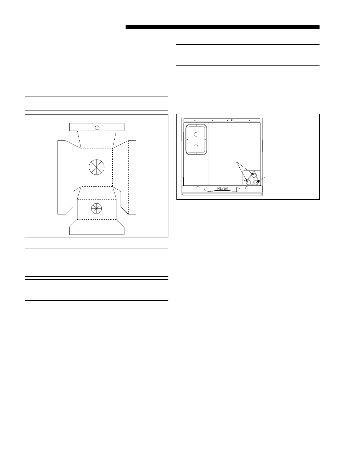
NOTE: Installation of the downflow baffle kit included
with unit is required on downflow applications. See
Figure 9.
c. Remove front shield by removing screws on
right side. Make sure to reinstall front shield af-
ter baffle changes. See Figure 9.
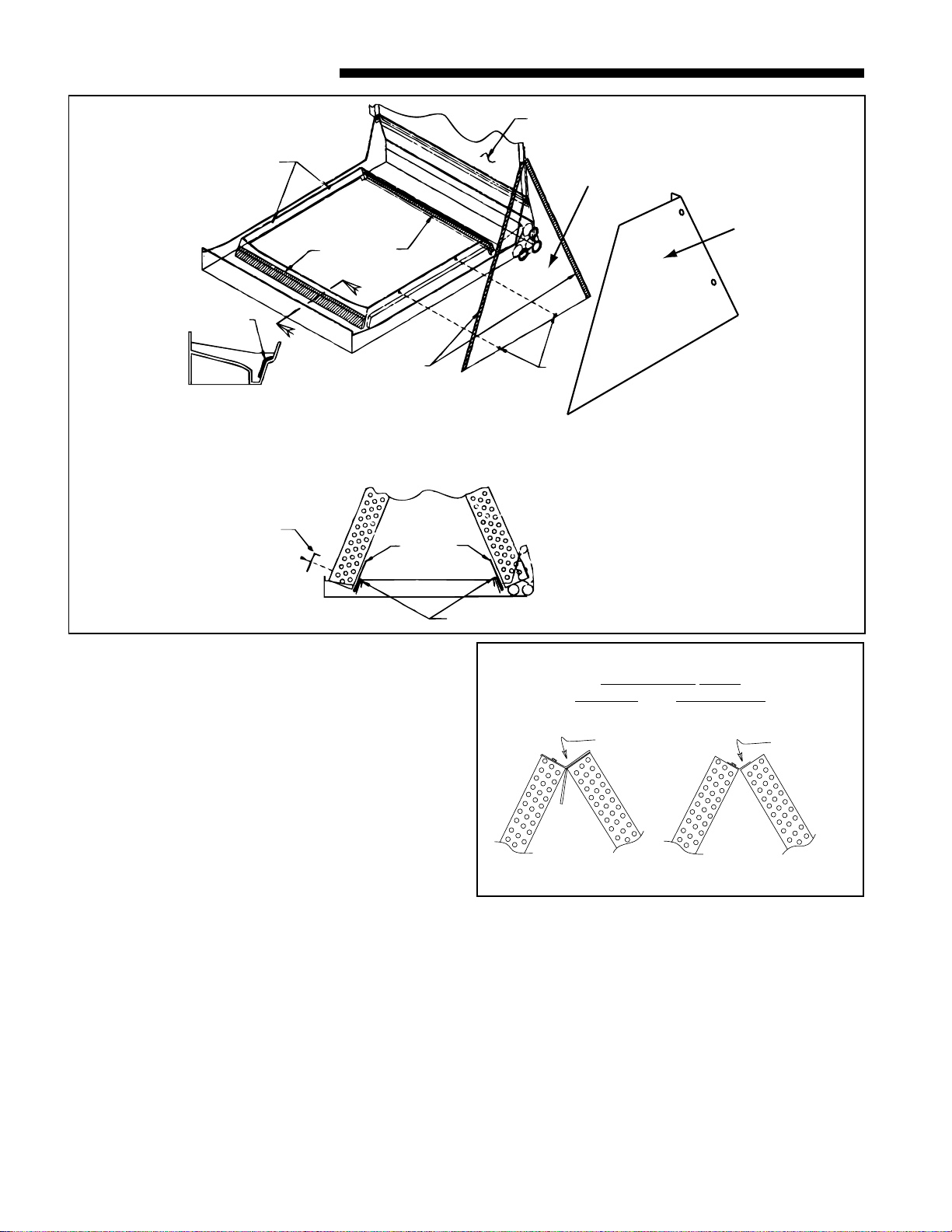
d. Remove the front triangular baffle from the coil
and install the 1/2" wide gasket provided per Fig-
ure 9. Trim the gasket length to fit the baffle. Re-
install the baffle to coil, with gasket material
compressed against the coil.
e. Install the water blow-off baffles provided on each
side of the coil with the flange at the top as
shown in Figure 9. The bottom of the baffle is to
be as close to the bottom of the coil as possible.
f. Install the 7/8" wide gasket in each side of the
drain pan as shown in Figure 9 (sect. X-X).
g. The 5 ton model (2/4TEE3D62) requires 2 water
diverter baffles to be placed underneath the coil
on the inside edge of the drain pan. See Figure 9.
Fill the bend in the baffle which fits the inner
edge of the drain pan with RTV type adhesive/
sealant before installing the baffle.
h. The unit is then placed with the blower side
down and the coil is replaced on the coil channel
supports with the drain connections at the bot-
tom. The unit is now in downflow position with
front access. Do not reattach coil support tab.
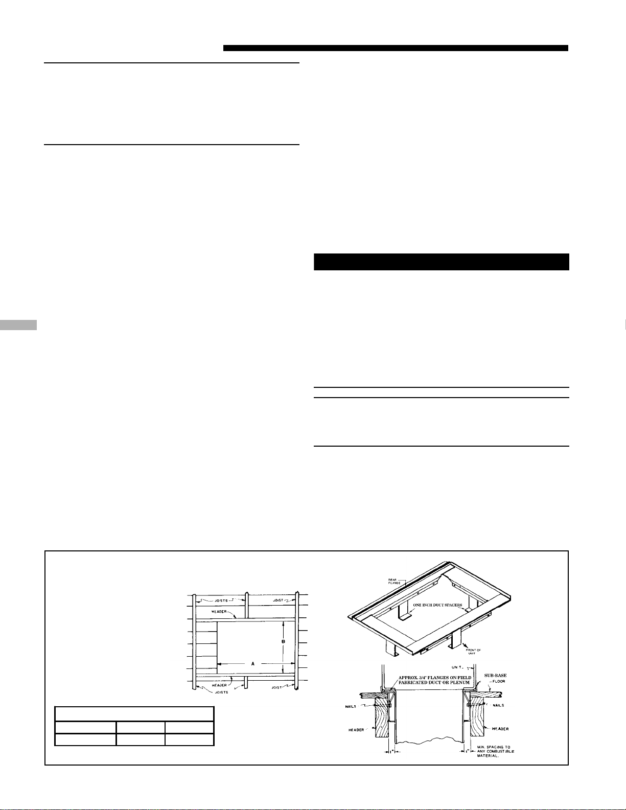
i. When supplementary heaters are used, accessory
subbase (TAYBASE102 for 2/4TEE3F62) must be
used. See Figure 1.
j. If a return duct is connected to the air handler, it
must be the same dimensions as the return
opening shown in the outline drawing on page
13.
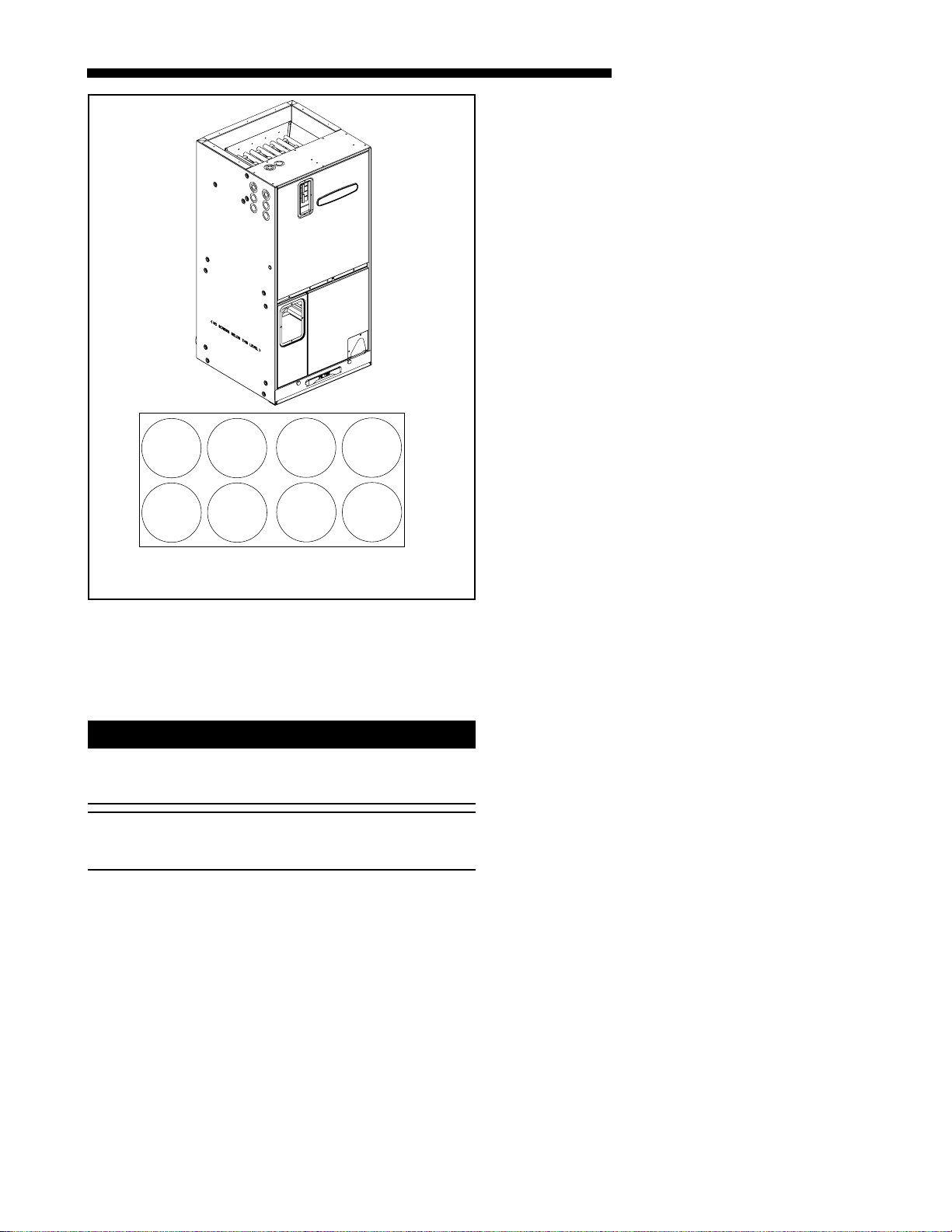
k. Openings where field wiring enters the
cabinet must be completely sealed. Location
of power entry is shown on the outline drawing.
Use 2.5" clear stickers provided to seal all unused
electrical knockouts. See Figure 8.
l. After ductwork connections are made, seal air-
tight and per Local codes.
HORIZONTAL LEFT
a. For maximum efficiency and Customer ease of
filter maintenance, it is recommended that a
properly sized remote filter and grille be in-
stalled for horizontal applications. Airflow should
not exceed the face velocity of the filter being
used. The factory installed filter should
then be removed from the unit.
b. To convert the unit to horizontal left, front ac-
cess, slide the coil out on the coil channel sup-
ports and rotate the complete coil 180 degrees.
c. Remove the factory installed baffle assembly
from the apex of the coil by using a 5/16"
nutdriver to remove the hex head screw. There
is a coil support tab at the top of the coil con-
nected to the case must be removed first. Re-
place this baffle with the factory supplied narrow
coil baffle using the screws removed previously.
See Figure 10.
d. The coil is then inserted back into the cabinet on
the opposite side coil channel supports. The unit
is now horizontal left with front access. Do not
reattach coil support tab.
e. If the unit is suspended, it must be supported
from the bottom near both ends as well as the
middle to prevent sagging. The service access
must remain unobstructed. If the unit is sup-
ported along the length of the front and back
with rails, the air handler only needs to be sus-
pended at both ends. See Figure 11.
Figure 8
Electrical Knockout Sticker Sheet
618-GE06D1-4
Installer’s Guide
If the unit is not suspended it must be supported
as mentioned above and isolated carefully to pre-
vent sound transmission. Vibration isolators (pur-
chased locally) must be placed under the unit.
f. It is always recommended that an auxiliary drain
pan be installed under a horizontal air handler
(See Condensate Piping) to prevent possible dam-
age to ceilings.
g. Isolate the auxiliary drain pan from the unit or
from the structure.
h. Connect the auxiliary drain line to a separate
drain line (no trap is needed in this line) and ter-
minate according to national and local codes.
i. If a return duct is connected to the air handler, it
must be the same dimensions as the return
opening shown in the outline drawing on page
13.
j. Openings where field wiring enters the
cabinet must be completely sealed. Location
of power entry is shown on the outline drawing.
Use 2.5" clear stickers provided to seal all unused
electrical knockouts. See Figure 8.
k. After ductwork connections are made, seal air-
tight and per Local codes.
HORIZONTAL RIGHT
a. For maximum efficiency and Customer ease of
filter maintenance, it is recommended that a
properly sized remote filter grille be installed
for horizontal applications. Airflow should not ex-
ceed the face velocity of the filter being used.
The factory installed filter should then be
removed from the unit.
b. Unit is shipped from the factory in the upflow or
horizontal right configuration. Unit conversion is
not required.
Remove
and
Discard
Replace
with
Narrow
Baffle
FOR MAXIMUM EFFICIENCY ON
HORIZONTAL LEFT,
UPFLOW AND DOWNFLOW
Figure 10
X
X
7/8" GASKET
SCREWS TO
REMOVE COIL
SCREWS TO
REMOVE COIL
DISCARD
DRIP TRAY
1/2" GASKET
INSIDE SURFACE
OF BAFFLE
7/8" GASKET
SECT. X-X
(TYP. BOTH SIDES)
FILL WITH SEALANT
WATER
BLOW-OFF
BAFFLES
ATTACH WITH
2 SCREWS
EACH SIDE
WATER
DIVERTER
BAFFLES
(5-ton only)
TRIANGULAR
BAFFLE
FRONT
SHIELD
DOWNFLOW BAFFLE KIT
Figure 9
18-GE06D1-4 7
Installer’s Guide
c. If the unit is suspended, it must be supported
from the bottom near both ends as well as the
middle to prevent sagging. The service access
must remain unobstructed. If the unit is sup-
ported along the length of the front and back, the
air handler only needs to be suspended at both
ends. See Figure 11.
d. If the unit is not suspended it must be isolated
carefully to prevent sound transmission. Vibra-
tion isolators (purchased locally) must be placed
under the unit.
e. It is always recommended that an auxiliary drain
pan be installed under a horizontal air handler
(See Condensate Drain Piping) to prevent pos-
sible damage to ceilings.
f. Isolate the auxiliary drain pan from the unit or
from the structure.
g. If a return duct is connected to the air handler, it
must be the same dimensions as the return
opening shown in the outline drawing on page
13.
h. If a return duct is connected to the air handler, it
must be the same dimensions as the return
opening shown in the outline drawings.
i. Openings where field wiring enters the cabi-
net must be completely sealed. Location of
power entry is shown on the outline drawing.
Use 2.5" clear stickers provided to seal all unused
electrical knockouts. See Figure 8.
j. After ductwork connections are made, seal air-
tight and per Local codes.
D. DUCT CONNECTIONS
The supply and return air ducts should be connected to
the unit with flame retardant duct connectors.
Rail
Figure 11 Mounting Installation Options
Flange Attachment
Figure 12
Convertible duct flanges are provided on the discharge
opening to provide a “flush fit” for 3/4" or 1-1/2" duct
board applications, see the Outline drawing on page 13
for sizes of the duct connections. After the duct is se-
cured, seal around the supply duct to prevent air leak-
age.
NOTE: If the convertible duct flanges are not used, they
must be removed and discarded for proper airflow.
E. REFRIGERANT PIPING
IMPORTANT:
Refrigerant piping must be routed to maintain service
access to blower compartment and provide easy re-
moval of filter access panel and filter.
NOTE: Penetration around the Refrigerant lines must
be sealed and Electrical inlets need to be sealed at
both the low and the high voltage.
818-GE06D1-4
Installer’s Guide
F. BRAZING TO EVAPORATOR SECTION
NOTE: A brazing shield is provided in the information
pack accompanying this unit. This shield fits over the
refrigerant fittings while brazing. Wet the shield before
brazing. See Figure 13.
IMPORTANT:
Do NOT unseal refrigerant tubing until ready to cut and
fit refrigerant lines.
1. Remove both sealing caps from indoor coil.
2. Field supplied tubing should be cut squared-off, en-
suring the tube is still round and free of burrs at
the connecting end. Clean the tubing to prevent
contaminants from entering the system.
3. Run refrigerant tubing into the stub sockets of in-
door unit coil. Refrigerant line openings must be
completely sealed.
4. Braze and evacuate according to indoor and outdoor
installation instructions.
5. Seal around refrigerant lines.
PAINTED AREAS OF UNIT MUST BE SHIELDED
DURING BRAZING
G. CONDENSATE DRAIN PIPING
NOTE:
Make certain that the unit has been installed in a level
position to ensure proper draining.
The indoor blower is downstream of the evaporator coil
which creates a negative pressure at the condensate
drain connections during operation. The condensate
drain connections in front of the indoor coil are 3/4"
NPT. The lower connection is the primary drain. See
Figure 14.
3/4" NPT Secondary
drain connection
3/4" NPT Primary
drain connection
Figure 14
BRAZE SHIELD
Figure 13
Two secondary drain connections are provided for the
different orientations (See Figure 6). The lower of the
two should be connected as a backup to prevent conden-
sate overflow by a blocked primary drain.
For proper drainage of condensate, the following steps
should be followed:
1. The primary drain line must be trapped with a
minimum of 2" water seal as shown in Figures 15 &
16. Do not use preformed 3/4" PVC running
traps.
The use of Field fabricated or manufactured traps
as shown in Figures 15 & 16 is acceptable. The
manufactured trap shown in Figure 15 allows for a
float switch option to be added.
Refer to the manufacturers data and instructions
for details.
2. The trap must be located within 4 feet of the air
handler drain outlet connection.
3. It is recommended that a clean-out tee or cross be
installed in the primary drain line for future main-
tenance (See Figure 15 & 16).
1. Refrigerant connections are made outside the cabi-
net.
2. Installation of refrigerant lines is covered in the in-
stallation instructions packaged with the outdoor
unit. Evacuation, leak testing and brazing proce-
dures are included in those instructions. Read those
instructions before starting installation of refriger-
ant lines.
NOTE: TXV Equipped is Non-Bleed, and may require a
start kit on the outdoor unit.
18-GE06D1-4 9
Installer’s Guide
H. ELECTRICAL — POWER WIRING
1. These Air Handlers are shipped from the factory
wired for 230 volts. The units may be wired for 208
volts. Follow instructions on unit wiring diagram lo-
cated on blower housing and in the Service Facts
document included with the unit.
2. The selection of wire and fuse sizes should be made
according to the Minimum Branch Circuit Ampacity
and the Maximum Overcurrent Device listed on the
unit nameplate.
▲
WARNING
!
TO PREVENT INJURY OR DEATH DUE TO ELECTRICAL
SHOCK OR CONTACT WITH MOVING PARTS, LOCK
UNIT DISCONNECT SWITCH IN OPEN POSITION BE-
FORE SERVICING UNIT.
3. Field wiring diagrams for electric heaters and unit
accessories are shipped with the accessory.
4. Wiring must conform to National and Local codes.
If an electric heater is not installed, connections are
made through the 7/8" knockout into the air handler
junction box to the two power leads and ground wire
connections which are located near the discharge of the
blower.
NOTE: If air handler is used with or without a heater,
the electrical entry hole as well as any other cabinet
penetrations must be sealed air-tight.
I. CONTROL WIRING
1. Connect wiring between indoor unit, outdoor unit
and Comfort Control. The use of color-coded low-
voltage wires is recommended.
2. A low voltage terminal board is provided for control
wiring, and is located on the left side of the cross
brace in the center of the unit.
3. Field wiring diagrams are provided which show the
low voltage wiring hookup for a single speed cooling
only system (with supplementary heaters) and a
heat pump system (with supplementary heaters).
Plug in type electrical connectors are provided for
use with supplementary heaters.
IMPORTANT:
When supplementary heaters are installed, inspect to
insure that all packaging material has been removed.
4. Do not use reducing fittings in the condensate drain
lines.
5. Slope the drain lines downward a minimum of 1/4"
per foot.
6. Insulate the primary drain to prevent sweating
where pipe temperature could meet or fall below
dewpoint temperatures.
7. Provide means for drainage to prevent winter
freeze-up of condensate line.
8. Do not connect the drain line to a closed drain sys-
tem.
9. Use Teflon®tape on the air handler drain line con-
nections! Do Not Use pipe joint compound or PVC/
CPVC cement!
It is always recommended that an auxiliary drain pan
be installed under a horizontally installed air handler.
Connect the auxiliary drain line to a separate drain line
(no trap is needed in this line) and terminate according
to local codes.
NOTE: DO NOT use a torch or flame near the plastic
drain pan coupling.
NOTE: DO NOT tighten the drain pipe excessively. Sup-
port the condensate piping and traps outside the unit
to prevent strain on the drain coupling.
Field fabricated trap
2" MIN.
2" MIN.
CAP OR PLUG
Trap must be within 4'
of air handler condensate
drain connection.
Close as possible
Figure 16
2" MINIMUM
2" MINIMUM
Manufactured traps
EZT-105 Figure 15
10 18-GE06D1-4
Installer’s Guide
COOLING OFF - DELAY OPTIONS
SWITCH SETTINGS SELECTION NOMINAL
AIRFLOW
5 - OFF 6 - OFF NONE SAME
5 - ON 6 - OFF 1.5 MINUTES 100% *
5 - OFF 6 - ON 3 MINUTES 50%
5 - ON 6 - ON ENHANCED** 50 - 100%
* - This setting is equivalent to the BAY24X045 relay benefit.
** - This ENHANCED MODE selection provides a ramping up
and ramping down of the blower speed to provide improved
comfort, quietness, and potential energy savings. The graph
shows the ramping process.
OFF OFF
50%
80%
100% if necessary
50%
Dehumidify
Fast Coil Cooling
and Heating Efficiency
7.5
minutes
3
minutes
1
minute
FAN OPERATION (CFM)
COMPRESSOR OPERATION ON OFF
as required
J. AIRFLOW ADJUSTMENT
▲
CAUTION
!
Disconnect power to the air handler before changing
dip switch positions. Failure to follow this procedure
may result in equipment damage.
Blower speed changes are made on the ECM Fan Con-
trol mounted on the control box. The ECM Fan Control
controls the variable speed motor.
There is a bank of 8 dip switches (See Figure 17). The
dip switches work in pairs to match the airflow for the
outdoor unit size (tons), cooling airflow adjustment, Fan
off-delay options, and heating airflow adjustment. The
switches appear as shown in Figure 18.
If the airflow needs to be increased or decreased, see
the Airflow Label on the air handler or the Blower Per-
formance Table in the Service Facts.
Information on changing the speed of the blower motor
for your specific outdoor model size is in the Blower
Performance Table.
Be sure to set the airflow for the correct tonnage.
Refer to blower housing for correct setting.
Switches 1 - 4 CoolingAirflow
Switches 5 - 6 Fan Off Delay Options
Switches 7 - 8 Auxiliary Heat
If the optional humidistat is used, remove R-BK jumper
from the low voltage terminal board (not shown) and in-
stall the humidistat between R and BK. (Jumper R to O
for cooling-only/non-heat pump systems with a humidis-
tat.)
INDOOR BLOWER TIMING
The FAN-OFF period is set on the ECM Fan Control
board by dip switches #5 and #6. The blower off-delay
settings are as follows:
IMPORTANT:
Leave dip switch 5 & 6 in the "as-shipped" position
during system start-up and check out. Afterwards, ad-
just as desired.
DIP SWITCHES (AS SHIPPED)
COOLING HEATING
AIRFLOW
FAN OFF
DELAY
AUXILIARY
HEAT SPEEDS
Figure 18
From Dwg. 800796a
CFM
SELECTION
LIGHT
DIP
SWITCHES
ECM FAN CONTROL
Figure 17
18-GE06D1-4 11
Installer’s Guide
HOOK-UP DIAGRAMS
COMFORT
CONTROL
VARIABLE SPEED
AIR HANDLER
HEAT PUMP
O.D. SECTION
(SINGLE SPEED)
HEAT PUMP
O.D. SECTION
(SINGLE SPEED)
AIR HANDLERS WITH 2 STAGE HEAT PUMP, 2 STAGE HEAT
AUTOMATIC OR MANUAL CHANGE OVER COMFORT CONTROL
From Dwg. 21B801073
COMFORT CONTROL
(AUTO)
2-STAGE HEAT/
2-STAGE COOL
VARIABLE SPEED
AIR HANDLER
COOLING
O.D. SECTION
(SINGLE SPEED)
COOLING
O.D. SECTION
(SINGLE SPEED)
AIR HANDLER WITH 2 STAGE COOLING, 2 STAGE HEAT
MANUAL COMFORT CONTROL
From Dwg. 21B801076
12 18-GE06D1-4
Installer’s Guide
COMFORT CONTROL
(MANUAL)
2-STAGE HEAT/
2-STAGE COOL
VARIABLE SPEED
AIR HANDLER
COOLING
O.D. SECTION
(SINGLE SPEED)
COOLING
O.D. SECTION
(SINGLE SPEED)
AIR HANDLER WITH 2 STAGE COOLING UNIT, 2 STAGE HEAT
AUTOMATIC CHANGE OVER COMFORT CONTROL
From Dwg. 21B801075
18-GE06D1-4 13
Installer’s Guide
OUTLINE DRAWING FOR 2/4TEE3F62
14 18-GE06D1-4
Installer’s Guide
2/4TEE3F62 AIR HANDLERS
H
W
21.0"
Model No. H W
2TEE3F62A1000A 62.75 24
4TEE3D62B1000A 62.75 24
18-GE06D1-4 15
Installer’s Guide
SUPPLEMENTARY HEATERS CHECKOUT PROCEDURES,
IF USED DOES HEATER REQUIRE A SPECIAL CIRCUIT?
SEE “LIMITATIONS AND RECOMMENDATIONS”
1. Be sure the disconnect switch is “OFF”, and safety label (if any) is attached...........................................[ ]
2. Check on field wiring for tight connections and grounding according to codes........................................[ ]
3. Check circuit protection for proper size per nameplate specifications .....................................................[ ]
4. Check control box panel — in place and secured.......................................................................................[ ]
NOTE: OPERATION OF HEATERS MUST BE CHECKED DURING THE OPERATION CHECK OF THE TOTAL
SYSTEM.
CHECKOUT PROCEDURES
After installation has been completed, it is recom-
mended that the Air Handler be checked against the
following checklist.
1. Make sure power is “OFF” at power disconnect switch
.................................................................................. [ ]
2. Check all field wiring for tight connections. See
that grounding of unit is in accord with code .......... [ ]
3. Make sure unit suspension (if used) is secure
and that there are no tools or loose debris in,
around or on top of the unit..................................... [ ]
4. Check all duct outlets; they must be open and unre-
stricted ...................................................................... [ ]
5. Check drain lines and be sure all joints are tight .. [ ]
6. Make sure secondary drain pan is installed ............ [ ]
7. Check power supply for correct requirements per unit
nameplate ................................................................. [ ]
8. Check filters for proper size. Inform owner of proper
procedure for removal and reinstallation .............. [ ]
9. Energize the system and carefully observe its
operation; make any necessary adjustment............ [ ]
10. Instruct owner, engineer (if possible) on proper operat-
ing procedure and leave Use and Care Manual with
owner ........................................................................ [ ]
P.I. 03/07
Since the manufacturer has a policy of continuous product and product data improvement, it reserves the
right to change design and specifications without notice.
American Standard Inc.
6200 Troup Highway
Tyler, TX 75707
For more information contact
your local dealer (distributor)
Installer’s Guide

This manual suits for next models

1

Other American Standard Air Handler manuals

American Standard TAM9A0A24V21DA Assembly instructions

American Standard

American Standard TAM9A0A24V21DA Assembly instructions

American Standard TMM5A0B24M21SAA Assembly instructions

American Standard

American Standard TMM5A0B24M21SAA Assembly instructions

American Standard 2TEE3D37A1000A Assembly instructions

American Standard

American Standard 2TEE3D37A1000A Assembly instructions

American Standard YC 24F/G1 Series Guide

American Standard

American Standard YC 24F/G1 Series Guide

American Standard TMM4A0A18S21SA Assembly instructions

American Standard

American Standard TMM4A0A18S21SA Assembly instructions

American Standard 4TEE3F31A Assembly instructions

American Standard

American Standard 4TEE3F31A Assembly instructions

American Standard TMM4A0A18S21SAA Assembly instructions

American Standard

American Standard TMM4A0A18S21SAA Assembly instructions

American Standard 2/4TEC3F18A1000A Assembly instructions

American Standard

American Standard 2/4TEC3F18A1000A Assembly instructions

American Standard TAM9A0A24V21DA Service manual

American Standard

American Standard TAM9A0A24V21DA Service manual

American Standard A5AHV002A1B30AA Installation and operating instructions

American Standard

American Standard A5AHV002A1B30AA Installation and operating instructions

Popular Air Handler manuals by other brands

Carrier Aero 39MN Series Installation, Start-Up and Service Instructions

Carrier

Carrier Aero 39MN Series Installation, Start-Up and Service Instructions

innovair 24000 Installation and owner's manual

innovair

innovair 24000 Installation and owner's manual

Kampmann KaCool HY 600x600 Installation, operation & maintenance manual

Kampmann

Kampmann KaCool HY 600x600 Installation, operation & maintenance manual

Goodman ACNF18 Series installation instructions

Goodman

Goodman ACNF18 Series installation instructions

PM-LUFT GOLD 1 Commissioning, operation, and maintenance

PM-LUFT

PM-LUFT GOLD 1 Commissioning, operation, and maintenance

Technibel PA 338 X operating instructions

Technibel

Technibel PA 338 X operating instructions

Trane CCE-Compact Series Installation operation & maintenance

Trane

Trane CCE-Compact Series Installation operation & maintenance

EQK 14S-EHVC18W2V user manual

EQK

EQK 14S-EHVC18W2V user manual

Armstrong Air BCE7E Series installation instructions

Armstrong Air

Armstrong Air BCE7E Series installation instructions

BLAUBERG Ventilatoren BlauAir RH user manual

BLAUBERG Ventilatoren

BLAUBERG Ventilatoren BlauAir RH user manual

BLAUBERG Ventilatoren KOMFORT LE Series Operation manual

BLAUBERG Ventilatoren

BLAUBERG Ventilatoren KOMFORT LE Series Operation manual

nilan CTS602 HMI installation instructions

nilan

nilan CTS602 HMI installation instructions

Amana ARUF**14 Series Installation & operating instructions

Amana

Amana ARUF**14 Series Installation & operating instructions

Ingersoll-Rand TAM7A0A24H21EA Installer manual

Ingersoll-Rand

Ingersoll-Rand TAM7A0A24H21EA Installer manual

BLAUBERG Ventilatoren SHM 100 DK user manual

BLAUBERG Ventilatoren

BLAUBERG Ventilatoren SHM 100 DK user manual

Aspen ABM Series Installation & operating instructions

Aspen

Aspen ABM Series Installation & operating instructions

ClimateMaster Tranquility TC L Series Installation operation & maintenance

ClimateMaster

ClimateMaster Tranquility TC L Series Installation operation & maintenance

DOSPEL OPTIMAL Series Maintenance Manual Warranty Card

DOSPEL

DOSPEL OPTIMAL Series Maintenance Manual Warranty Card

manuals.online logo
manuals.online logoBrands
  • About & Mission
  • Contact us
  • Privacy Policy
  • Terms and Conditions

Copyright 2025 Manuals.Online. All Rights Reserved.