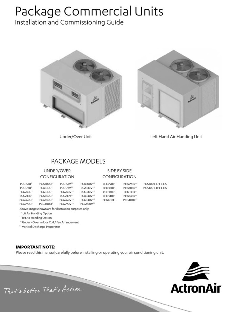
2Installation and Commissioning Guide 500-700 Tri-Capacity Split Ducted
Doc. No.0525-098 Ver. 2 210330
Installation and Commissioning Guide Split Tri-Capacity
Table of Contents
01. INTRODUCTION ..............................................................................................................................4
. Product Inspections
. Codes, Regulations and Standards
02. GENERAL INFORMATION.................................................................................................................4
03. SAFETY PRECAUTION ......................................................................................................................6
04. INSTALLATION INFORMATION ........................................................................................................ 7
05. UNIT MOUNTING AND LOCATION................................................................................................... 8
06. COMPONENTS OVERVIEW...............................................................................................................9
. Outdoor Unit
. Indoor Unit - Standard Profile
. Indoor Unit - Low Profile
07. OUTDOOR DIMENSIONS ................................................................................................................12
. CAYT Unit Dimension
. CAYT - CAYT Unit Dimension
. Outdoor Base Dimension
08. INDOOR DIMENSIONS ...................................................................................................................15
. EVYT Unit Dimension
. EVYT - EVYT Unit Dimension
. ELYT Unit Dimension
. ELYT - ELYT Unit Dimension
09. UNIT LIFTING PROCEDURE..............................................................................................................19
. Crane Lifting Method
. Fork Lift Method
10. CONDENSATE AND SAFETY TRAY DRAINAGE INSTRUCTIONS.........................................................21
11. BANKING OF OUTDOOR UNITS...................................................................................................... 22
. End-To-End Configuration
. Cluster Configuration
. Side-By-Side Configuration
12. LAYOUT - OUTDOOR UNIT CONTROL BOX .................................................................................... 23
. Standard Model
. Standard Model with Optional -Phase Protection Relay
. Standard Model with Optional -Phase Soft Starters
. With Optional EC Outdoor Fans
. With Optional EC Outdoor Fans and -Phase Protection Relay
. With Optional EC Outdoor Fans and -Phase Soft Starters
. Indoor Unit Control Box - Standard Models
13. UNIT PREPARATION....................................................................................................................... 28
. Outdoor Unit - Interconnecting Pipes Installation
. Compressor Shipping Blocks Removal
. Electrical Mains
14. PIPING ............................................................................................................................................31
. Piping Connection
. Example Total Equivalent Field Pipe Length Calculations
. Pipe Installation
15. ELECTRICAL................................................................................................................................... 36
. Split Unit Electrical Connection
. Maximum Cable Lengths
. BMS Control Wiring Procedures
. Return Air - Outside Air - Spill Air Control Wiring Procedures
. Demand Response Management


