Set up the Relay
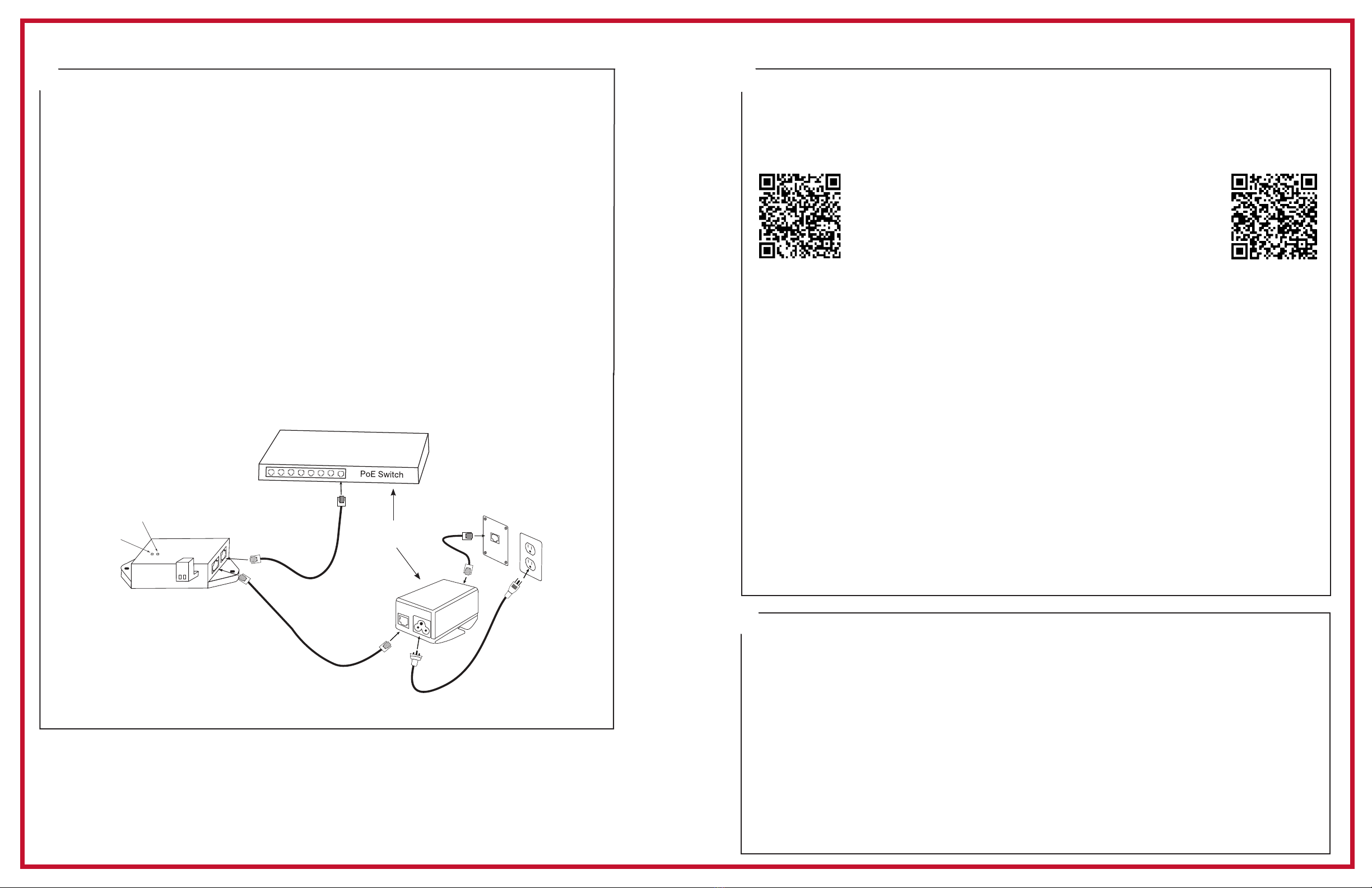
1. Apply power to the Relay by connecting a CAT 5 or higher Ethernet patch cable (A) from
a PoE switch or single injector to the PoE Relay (D).
—PoE Switch - Check with network administrator for infrastructure needs. This part
is not supplied by American Time.
—PoE Injector (TMA200) - This is an optional power source that may be purchased from
American Time.
2. The Status LED (B) will indicate the relay's status as follows:
—Flashing Orange: Acquiring an IP address using DHCP
—Flashing Red: Attempting SNTP sync
—Continuous Red: Failed SNTP sync
—Continuous Green: Successful SNTP sync
Note: When a DHCP network is not present at initial start up, the PoE Relay will default
to a random Static IP in the range of 169.254.1.0 to 169.254.254.255.
For more details reference the PoE Analog and Global Series Digital Manual.
Navigate to: SUPPORT > PRODUCT DOCUMENTATION > select MANUAL > type PoE in
searchbox > SEARCH – Click on PoE Analog and Global Series Digital Manual.
3. The Relay LED (C) designates the Relay is enabled.
A=PoE connection (CAT 5 or higher Ethernet patch cable) B=Status LED C=Relay LED
D=H004896R Relay
QUICK START INSTALLATION GUIDE H004896R PoE RELAY
4
Status LED
Relay Active LED
Injector
A
B
C
D
A
or
Activating Relay to the inCloud Portal
(Note: for non-inCloud subscribers, see "Adjustments via Network Clock Connect" below.)
To easily activate your relay on the inCloud Management portal, download American Time's
Network Clocks mobile app for Android devices (see QR code provided below).
If relay must be activated using a computer, follow the steps listed below.
1. Navigate to the inCloud portal: incloud.american-time.com
Log in using the credentials supplied in the welcome e-mail from American Time.
2. Click on the green "Setup New" button in the PoE Devices bar on the Device List page.
This will open the Setup Network Device List, which will list all the devices assigned to your
site by American Time.
3. Find the relay's MAC address and provide a Title and (if desired) description for the relay.
Repeat this for each device in the list which you want to set up.
• The MAC address can be searched using the last ve characters of the address including
the colon (for example, AA:11) in the search bar.
4. The relay will remain in a semi-activated state until they report in to the portal. As
long as the relays have not yet been powered up, this should occur once power is
connected. Otherwise, this may take up to 15 minutes to occur.
If relays cannot be activated prior to installation/power-up:
•Follow the same process outlined in this instruction sheet. After activation, relays
will appear as partially activated in the Device List until they communicate with inCloud
fully; this may take up to 24 hours, but relays will function normally until that occurs.
• If immediate connection is desired, removing and then reconnecting power to the relays
will command them to communicate with inCloud immediately. This must be performed with
each relay if desired.
Scan the QR code to the left
to download the Network
Clocks mobile app. The
app allows you to quickly
and easily set up clocks on
inCloud.
Scan the QR code to the
right to access the quickstart
guide for the Network Clocks
mobile app.
5
Adjustments via Network Clock Connect (for non-inCloud users)
1. Download Network Clock Connect. Find it online: american-time.com
Navigate to: SUPPORT > PRODUCT DOCUMENTATION > select FIRMWARE > SEARCH
Click on Network Clock Connect.
The software will automatically download. It is also available from the optional USB
Drive (H004167B-POE, purchased separately).
2. Install Network Clock Connect application – Password = clock4u (default)
3. Network Clock Connect will allow you to congure:
• Network address settings
• Time Synchronization settings
• Daylight Saving Time settings
• Schedules (Buzzer clocks) - maximum of 100 scheduled events
For more details, reference the PoE Analog and Global Series Digital Manual.
6


