manuals.online logo
Brands
  1. Home
  2. •
  3. Brands
  4. •
  5. Omron
  6. •
  7. Relay
  8. •
  9. Omron G3PA-VD Series User manual

Omron G3PA-VD Series User manual

132
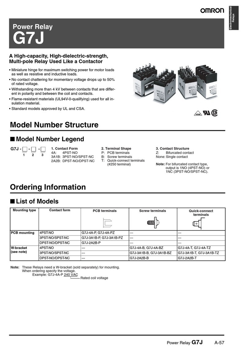
Power Solid-state Relay G3PA-(VD)
Extremely Thin Relays Integrated with
Heat Sink
Downsizing achieved through optimum design of
heat sink.
Mounting possible via screws or via DIN rail.
Close mounting possible for linking terminals.
(Except for G3PA-260B-VD.)
Applicable with 3-phase loads.
Replaceable power element cartridges.
Conforms to VDE 0160 (finger protection), with a
dielectric strength of 4,000 V between input and
load.
Conforms to VDE 0805, IEC 950.
Approved by UL, CSA, and VDE. RCW
Ordering Information
Model Isolation Zero
cross function
Indicator
Applicable output load Rated input voltage
G3PA-210B-VD Phototriac
l
Yes Yes
10 A at 24 to 240 V
AC
5 to 24 VDC
G3PA-220B-VD
oo ac
coupler
es
es
20 A at 24 to 240 V
AC
5o C
G3PA-240B-VD
40 A at 24 to 240 V
AC
G3PA-260B-VD
60 A at 24 to 240 V
AC
G3PA-210BL-VD No
10 A at 24 to 240 V
AC
G3PA-220BL-VD
o
20 A at 24 to 240 V
AC
G3PA-240BL-VD
40 A at 24 to 240 V
AC
G3PA-260BL-VD
60 A at 24 to 240 V
AC
G3PA-210B-VD Yes
10 A at 24 to 240 V
AC
24 V
AC
G3PA-220B-VD
es
20 A at 24 to 240 V
AC
C
G3PA-240B-VD
40 A at 24 to 240 V
AC
G3PA-260B-VD
60 A at 24 to 240 V
AC
G3PA-420B-VD
20 A at 180 to 400 V
AC
12 to 24 VDC
G3PA-430B-VD
30 A at 180 to 400 V
AC
oC
G3PA-420B-VD-2
20 A at 200 to 480 V
AC
G3PA-430B-VD-2
30 A at 200 to 480 V
AC
G3PA-450B-VD-2
50 A at 200 to 480 V
AC
G3PA-(VD) G3PA-(VD)
133
Replacement Parts
Name Carry
current
Model
Applicable SSR
Power Device Cartridge
10 A
G32A-A10-VD DC5-24 G3PA-210B-VD DC5-24
o e e ce Ca dge
0
G32A-A10L-VD DC5-24 G3P
A-210BL-VD DC5-24
G32A-A10-VD AC24 G3PA-210B-VD AC24
20 A
G32A-A20-VD DC5-24 G3PA-220B-VD DC5-24
0
G32A-A20L-VD DC5-24 G3P
A-220BL-VD DC5-24
G32A-A20-VD AC24 G3PA-220B-VD AC24
40 A
G32A-A40-VD DC5-24 G3PA-240B-VD DC5-24
0
G32A-A40L-VD DC5-24 G3P
A-240BL-VD DC5-24
G32A-A40-VD AC24 G3PA-240B-VD AC24
60 A
G32A-A60-VD DC5-24 G3PA-260B-VD DC5-24
60
G32A-A60L-VD DC5-24 G3P
A-260BL-VD DC5-24
G32A-A60-VD AC24 G3PA-260B-VD AC24
20 A
G32A-A420-VD DC12-24
G3P
A-420B-VD DC12-24
30 A
G32A-A430-VD DC12-24
G3P
A-430B-VD DC12-24
20 A
G32A-A420-VD-2 DC12-24
G3P
A-420B-VD-2 DC12-24
30 A
G32A-A430-VD-2 DC12-24
G3P
A-430B-VD-2 DC12-24
50 A
G32A-A450-VD-2 DC12-24
G3P
A-450B-VD-2 DC12-24
Other Units (Order Separately)
Units that Enable 2-line Switching of 3-phase Power
Name Current flow Model
Applicable SSR
Short-circuit Unit
10 A
G32A-D20 G3PA-210B-VD
So ccu U
20 A
G3 0
G3PA-220B-VD
G3PA-420B-VD,
G3PA-420B-VD-2
30 A
G32A-D40 G3PA-430B-VD,
G3PA-430B-VD-2
40 A
G3PA-240B-VD
Specifications
Ratings (at 25°C)
Input
Model Rated
voltage
V
oltage range
Input current
impedance V
oltage level
Must operate voltage
Must release voltage
G3PA-210B-VD
5 to 24 VDC 4 to 30 VDC 7 mA max.
4 VDC max.
1 VDC min.
G3PA-220B-VD
5o C
o30 C
a
Ca
C
G3PA-240B-VD
G3PA-260B-VD
G3PA-210BL-VD
5 to 24 VDC 4 to 30 VDC
20 mA max.
4 VDC max.
1 VDC min.
G3PA-220BL-VD
5o C
o30 C
0a
Ca
C
G3PA-240BL-VD
G3PA-260BL-VD
G3PA-210B-VD
24 V
AC
19.2 to 26.4 V
AC
1.4 k
Ω±20%
19.2 V
AC max.
4.8 V
AC min.
G3PA-220B-VD
C
9o6
C
0%
9
Ca
8
C
G3PA-240B-VD
G3PA-260B-VD
G3PA-420B-VD
12 to 24 VDC 9.6 to 30 VDC
7 mA max.
9.6 VDC max.
1 VDC min.
G3PA-430B-VD
oC
96 o30 C
a
96 C a
C
G3PA-420B-VD-2
G3PA-430B-VD-2
G3PA-450B-VD-2
G3PA-(VD) G3PA-(VD)
134
Output
Model
Applicable load
Load voltage
Load current
Inrush current
G3PA-210B(L)-VD
19 to 264 V
AC (50/60 Hz)
0.1 to 10 A
150 A (60 Hz, 1 cycle)
G3PA-220B(L)-VD
9o 6
C (50/60 )
0.1 to 20 A
220 A (60 Hz, 1 cycle)
G3PA-240B(L)-VD
0.5 to 40 A
440 A (60 Hz, 1 cycle)
G3PA-260B(L)-VD
0.5 to 60 A
440 A (60 Hz, 1 cycle)
G3PA-420B-VD
150 to 440 V
AC (50/60 Hz)
0.5 to 20 A
220 A (60 Hz, 1 cycle)
G3PA-430B-VD
50 o 0
C (50/60 )
0.5 to 30 A
440 A (60 Hz, 1 cycle)
G3PA-420B-VD-2
180 to 528 V
AC (50/60 Hz)
0.5 to 20 A
220 A (60 Hz, 1 cycle)
G3PA-430B-VD-2
80 o 5 8
C (50/60 )
0.5 to 30 A
440 A (60 Hz, 1 cycle)
G3PA-450B-VD-2
0.5 to 50 A
440 A (60 Hz, 1 cycle)
Refer to
Engineering Data
for further details.
Characteristics
Item G3PA-
210B(L)-VD G3PA-
220B(L)-VD G3PA-
240B(L)-VD G3PA-
260B(L)-VD G3PA-
420B-VD G3PA-
420B-VD-2 G3PA-
430B-VD G3PA-
430B-VD-2 G3PA-
450B-VD-2
Operate
time
1/2 of load power source cycle + 1 ms max. (DC Input, -B models)
1 1/2 of load power source cycle + 1 ms max. (AC Input)
1 ms max. (-BL models)
Release time
1/2 of load power source cycle + 1 ms max. (DC Input)
1 1/2 of load power source cycle + 1 ms max. (AC Input)
Output ON
voltage drop
1.6 V (RMS) max. 1.8 V (RMS) max.
Leakage
current
5 mA max. (at 120 V
AC)
10 mA max. (at 230 V
AC)
10 mA max. (at 120 V
AC)
20 mA max. (at 230 V
AC)
20 mA max. (at 400 V
AC)
I2t
260 A
2S
810 A
2S
260 A
2S
810 A
2S
810 A
2S
Insulation
resistance
100 M
Ω
min. (at 500 VDC)
Dielectric
strength
4,000 V
AC, 50/60 Hz for 1 min
Vibration
resistance
Malfunction: 10 to 55 Hz, 0.75-mm double amplitude (mounted to DIN rail)
Shock
resistance
Malfunction: 300 m/s
2
(mounted to DIN rail)
Ambient
temperature Operating: –30°
C to 80
°
C (with no icing or condensation)
Storage: –30°
C to 100
°
C (with no icing or condensation)
Approved
standards
UL508 File No.E64562, CSA C22.2 (No.14, No.950) File No.LR35535, EN60950 File No.
5915UG
Approval expected in Mar 2000
Ambient
humidity
Operating: 45% to 85%
Weight
Approx.
260 g
Approx.
340 g
Approx.
460 g
Approx.
900 g
Approx.
290 g
Approx.
290 g
Approx.
410 g
Approx.
410 g
Approx.
900 g
G3PA-(VD) G3PA-(VD)
135
Engineering Data
ÉÉÉÉÉ
Ambient
temperature (
°C)
Ambient temperature (
°C)
Ambient temperature (
°C)
Load current (A)
Load current (A)
Load current (A)
Load Current vs. Ambient
Temperature Characteristics
Horizontal Mounting to Ground
G3PA-240B(L)-VD G3PA-260B(L)-VD
G3PA-220B(L)-VD
G3PA-210B(L)-VD
25
15
G3PA-210B(L)-VD, G3PA-220B(L)-VD
Panel Ground
40 60 80 100200–20–30
60
40
25
20
80
Ambient temperature (
°C)
Ambient temperature (
°C)
Load current (A)
Load current (A)
G3PA-430B-VD, G3PA-430B-VD-2
G3PA-420B-VD, G3PA-420B-VD-2 G3PA-450B-VD-2
Ambient temperature (
°C)
Load current (A)
Note: Close
mounting is possible for a maximum of three Units by reducing the load current by 20%. (A minimum clearance of 10 mm must be
provided
when mounting four or more Units.)
G3PA-(VD) G3PA-(VD)
136
Characteristics Between Input Voltage
and Input Current
G3PA-2j0B-VD
Input current (mA)
Input
voltage (V)
8.0
0.0 0 5 10 20 25 3015
6.0
4.0
2.0
Input current (mA)
Input voltage (V)
G3PA-4jB-VD
ÉÉÉÉÉ
ÉÉÉÉÉ
Vertical Mounting to Ground
Ambient
temperature (
°C)
Ambient temperature (
°C)
Ambient temperature (
°C)
Load current (A)
Load current (A)
Load current (A)
40 60 80 100200–20–30
G3PA-240B(L)-VD G3PA-260B(L)-VD
60
40
42
20
G3PA-220B(L)-VD
G3PA-210B(L)-VD
3.5
11
28
15
11
14
18
20
10
5
5.5 10
Panel
Ground
G3PA-210B(L)-VD, G3PA-220B(L)-VD
7
Ambient temperature (
°C)
Load current (A)
G3PA-420B-VD, G3PA-430B-VD
G3PA-420B -VD-2, G3PA-430B-VD-2
G3PA-430B-VD
G3PA-420B-VD
G3PA-450B-VD-2
Ambient temperature (
°C)
Load current (A)
G3PA-(VD) G3PA-(VD)
137
ÉÉÉÉÉ
Close Mounting (Up to Three)
Ambient
temperature (
°C)
Ambient temperature (
°C)
Ambient temperature (
°C)
Load current (A)
Load current (A)
Load current (A)
40 60 80 100200–20–30
G3PA-240B(L)-VD G3PA-260B(L)-VD
64
40
48
20
G3PA-220B-VD
G3PA-210B-VD
18
4.5
36
15
13
20
30
5
7
40
45
30
20
10
14
G3PA-210B(L)-VD, G3PA-220B(L)-VD
DIN
track
Panel Ground
Ambient
temperature (
°C)
Ambient temperature (
°C)
Load current (A)
G3PA-430B-VD, G3PA-430B-VD-2G3PA-420B-VD, G3PA-420B-VD-2
Load current (A)
30
20
16
10
–30 10 30 80 100
40
30
24
20
10
–30 10 30 80
9
27
G3PA-450B-VD-2
Ambient temperature (
°C)
Load current (A)
G3PA-(VD) G3PA-(VD)
138
Inrush Current Resistivity
Non-repetitive
(Keep the inrush current to half the rated value if it occurs repetitively
.)
G3PA-210B(L)-VD G3PA-220B(L)-VD G3PA-240B(L)-VD/260B(L)-VD
Inrush current (A. Peak)
Energizing time (ms)
Inrush current (A. Peak)
Energizing time (ms)
Inrush current (A. Peak)
Energizing time (ms)
G3PA-430B-VD, G3PA-430B-VD-2, G3PA-450B-VD-2
Inrush current (A. Peak)
Energizing time (ms)
Inrush current (A. Peak)
Energizing time (ms)
G3PA-420B-VD, G3PA-420B-VD-2
G3PA-(VD) G3PA-(VD)
139
Nomenclature
G3PA-210B-VD
G3PA-220B-VD
G3PA-240B-VD
G3PA-260B-VD
Protective
cover
Power Device Cartridge
Note: Use the special tool for replacement of
the cartridge (G3PA-210B-VD/-220B-VD
models only).
Operation indicator
Temperature indicator
Linking terminal
(except for G3PA-260B-VD)
Heat sink
DIN track mounting part
(G3PA-220B-VD) Mounting hole
Protective
cover
Power Device
Cartridge
Linking terminal
(except for G3PA-260B-VD)
Heat sink
DIN track mounting part
(G3PA-240B-VD)
Operation indicator
Temperature indicator
Mounting hole
G3PA-420B-VD
G3PA-430B-VD
G3PA-(VD) G3PA-(VD)
140
Operation
Renewal Parts
G32A-A Power Device Cartridge
The
G32A-A Power Device Cartridge (a T
riac Unit) can be replaced with a new one. When the temperature indicator
has changed from pink to
red,
the triac circuitry may have malfunctioned possibly by an excessive flow of current, in which case, dismount the
damaged cartridge for
replacement.
The
damaged cartridge can be replaced with a new one without disconnecting the wires from the G3P
A.
Improve the heat radiation ef
ficiency of the G3P
A before replacing the cartridge.
The
G32A-A Power Device Cartridge can withstand an excessive current for a short period of time, such as may be caused accidentally by the
short
circuitry of the load, in which case the temperature indicator will not turn red.
Appearance
G32A-A10-VD G32A-A20-VD G32A-A40-VD G32A-A60-VD
G32A-A420-VD G32A-A430-VD
G32A-A10
G32A-A20 G32A-A40
Replacement Parts
Name Carry
current Load
voltage
Model
Applicable SSR
Conforms to
VDE
Power Device
Ctid
10 A
19 to 264 V
AC G32A-A10-VD DC5-24 G3PA-210B-VD DC5-24 Yes
oe ece
Cartridge
0
9o 6
C
G32A-A10L-VD DC5-24 G3P
A-210BL-VD DC5-24
es
G32A-A10-VD AC24 G3PA-210B-VD AC24
20 A
G32A-A20-VD DC5-24 G3PA-220B-VD DC5-24
0
G32A-A20L-VD DC5-24 G3P
A-220BL-VD DC5-24
G32A-A20-VD AC24 G3PA-220B-VD AC24
40 A
G32A-A40-VD DC5-24 G3PA-240B-VD DC5-24
0
G32A-A40L-VD DC5-24 G3P
A-240BL-VD DC5-24
G32A-A40-VD AC24 G3PA-240B-VD AC24
60 A
G32A-A60-VD DC5-24 G3PA-260B-VD DC5-24
60
G32A-A60L-VD DC5-24 G3P
A-260BL-VD DC5-24
G32A-A60-VD AC24 G3PA-260B-VD AC24
20 A
150 to 440 V
AC
G32A-A420-VD DC12-24
G3P
A-420B-VD DC12-24
30 A
50 o 0
C
G32A-A430-VD DC12-24
G3P
A-430B-VD DC12-24
20 A
180 to 528 V
AC
G32A-A420-VD-2 DC12-24
G3P
A-420B-VD-2 DC12-24
30 A
80 o 5 8
C
G32A-A430-VD-2 DC12-24
G3P
A-430B-VD-2 DC12-24
50 A
G32A-A450-VD-2 DC12-24
G3P
A-450B-VD-2 DC12-24
10 A
75 to 264 V
AC G32A-A10 G3P
A-210B DC5-24
No
20 A
5o 6
C
G32A-A20 G3P
A-220B DC5-24
o
40 A
G32A-A40 G3P
A-240B DC5-24
20 A
180 to 528 V
AC G32A-A420 G3P
A-420B DC5-24
30 A
80 o 5 8
C
G32A-A430 G3P
A-430B DC5-24
G3PA-(VD) G3PA-(VD)
141
Note: 1.
Replacing Power Device Cartridges
When
replacing Power Device Cartridges, use the specified model. Using a Power Device Cartridge other than the specified one
will
result in faulty operation and destruction of the elements.
2. Noise T
erminal V
oltage according to EN5501
1
Conformance
to EN5501
1 is possible if a capacitor is connected to the load power supply as shown in the diagram below
. (G3P
A-
VD)
Input G3PA-VD
Load
240 VAC
24 VDC
Replacement
Note: Be
sure to turn OFF the power supply when replacing the Cartridge. Supplying power with the Cartridge removed may result in mal
-
function.
G32A-A10-VD/G32A-A20-VD/G32-A420-VD
Use
the special tool (provided) to extract the cartridge for replacement with a new one.
Extraction
Follow the procedures below to dismount the Power Device Car-
tridge
from the G3P
A.
1. Switch off the power.
2.
Remove the terminal cover
.
3. Hook
the indented part of the cartridge with the tool and pull
up
on the cartridge to remove it.
Remover
Hook here with
Remover.
Mounting
Follow
the procedures below to
mount the Power Device Cartridge
on
the G3P
A.
1. Apply
silicone grease (provided with the G32A-A) to the entire
surface
of the heat radiator
.
Apply silicone grease here.
2. Make
sure that there is no dust or pieces of wire on the heat
radiator
of the G32A-A or the G3P
A.
3.
Insert the cartridge into the
opening of the G3P
A so that the
letters
on the cartridge and those on the G3P
A are in the same
direction
and side A and side B are even.
Side A
Side B
4. Attach
the terminal cover
.
5. Switch
on the power and check the G3P
A to be sure it works
properly.
G3PA-(VD) G3PA-(VD)
142
G32A-A10/G32A-A20
Use
the special tool (provided) to extract the cartridge for
replace
-
ment
with a new one.
Extraction
Follow the procedures below to dismount the Power Device Car-
tridge
from the G3P
A.
1. Switch off the power.
2.
Remove the terminal cover
.
3. Hook
the indented part of the cartridge with the tool and pull
up
on the cartridge to remove it.
Remover
Hook here with
Remover.
Mounting
Follow
the procedures below to
mount the Power Device Cartridge
on
the G3P
A.
1. Apply
silicone grease (provided with the G32A-A) to the entire
surface
of the heat radiator
.
Apply silicone grease here.
2. Make
sure that there is no dust or pieces of wire on the heat
radiator
of the G32A-A or the G3P
A.
3.
Insert the cartridge into the
opening of the G3P
A so that the
letters
on the cartridge and those on the G3P
A are in the same
direction
and side A and side B are even.
Side A
Side B
4. Attach
the terminal cover
.
5. Switch
on the power and check the G3P
A to be sure it works
properly.
G32A-A40
The Power Device Cartridge is secured with screws.
Extraction
1. Switch off the power.
2.
Remove the terminal cover
.
3. Loosen and remove the two middle screws. These screws
are connected to terminals 1 and 2. (For safety reasons, be
sure to turn the power supply of
f.)
Loosen
Loosen
4.
Loosen the screws in the corners.
Loosen
Loosen
5. Hold
the indented parts on both sides of the cartridge and pull
up
on the cartridge to remove it.
Mounting
Follow
the procedures below to
mount the Power Device Cartridge
on
the G3P
A.
1. Apply
silicone grease to the entire
surface of the heat radiator
.
Apply silicone grease here.
2. Make
sure that there is no dust or pieces of wire on the heat
radiator
of the G32A-A or the G3P
A-240B.
3. Insert the cartridge into the opening of the G3PA-240B.
(Insert
until side A and side B are even.)
Side A
Side B
4. T
ighten the screws in the corners. (T
ightening torque: 0.59
to
0.78 NSm)
5. Tighten the middle screws. (Tightening torque: 0.59 to 0.78
NSm)
6. Attach
the terminal cover
.
7. Switch
on the power and check the G3P
A to be sure it works
properly.
G3PA-(VD) G3PA-(VD)
143
G32A-A40-VD/G32A-A60-VD/G32A-A430-VD
The
G32A Power Device Cartridge is mounted and secured with screws to the G3P
A Unit.
Extraction
Follow the procedures below to dismount the G32A-A Power De-
vice
Cartridge from the G3P
A.
1. Switch off the power.
2.
Remove the terminal cover
.
3. Loosen
the two centered screws on the sides to dismount the
cartridge.
The screws are connected to terminals 1 and 2.
Loosen
Loosen
4.
Loosen the screws on both the corners.
Loosen
Loosen
5. Hold the indented part of both the corners to dismount the
cartridge.
Mounting
1. Apply
silicone grease to the entire
surface of the heat radiator
.
Apply silicone grease here.
2. Make sure that there is no dust or pieces of wire on the
radiator
of the G32A-A or the G3P
A.
3. Insert
the cartridge into the opening of the G3P
A so that side A
and
side B are even.
Side B
Side A
4. Tighten the screws on both the corners with a tightening
torque
of 0.59 to 0.78 N
S
m.
5. Tighten
the screws on both the sides with a tightening torque
of
0.59 to 0.78 N
S
m.
6.
Attach the terminal cover
.
7. Switch
on the power and check the G3P
A to be sure it works
properly.
G3PA-(VD) G3PA-(VD)
144
Linking Terminal Connection
•Connecting with linking terminal for G3PA-210B-VD,
-220B-VD,
-240B-VD and G3P
A-420B-VD, G3P
A-430B-VD.
1. When SSRs are close
mounted, loosen the
M3.5 Sems screw and
flip the linking terminal
down.
2. Insert the linking
terminal securely
into the center of
the screw and
tighten
the screw
.
SSR1 SSR2 SSR1 SSR2
•Connecting
with linking terminal for G32A.
1. When SSR are close
mounted, loosen the
M3.5 Sems screw on
the G32A and flip the
linking
terminal down.
2. Insert
the linking termi
-
nal securely into the
center
of the screw and
tighten the screw. En-
sure that the linking
terminal does not pro-
trude.
SSR G32A Unit SSR G32A Unit
*
* The cover will not fit if
the terminal protrudes.
Linking terminal
Linking terminal
Linking
terminal
Linking
terminal
Connect
the terminal with power of
f.
Refer to the instruction manual for
the G32A-A Power Device Cartridge
to replace the G3PA’
s triac part.
When the temperature indicator has turned from pink to red, the G32-A-A Power Device Car-
tridge may have malfunctioned, in which case the cartridge must be replaced with a new one. Use the terminal cover to prevent accidents
due to electric shock.
G3PA-420B-VD
G3PA-(VD) G3PA-(VD)
145
ÉÉÉÉÉ
ÉÉÉÉÉ
Close
Mounting
At a rated ambient temperature for each.
Note: Keep a distance of 3 cm or more between the G3PA
(especially
the SSR on the upper side) and the duct.
Screw or DIN track mounting is possible.
Mount horizontally to ground.
Panel
Close mounting of up to three G3P
A
SSRs is possible.
Load current should be reduced by 10%
for G3P
A-210B-VD, -220B-VD, -240B-
VD, and by 20% for other models.
T
o close mount more than three G3P
A,
keep a distance of 10 mm between each
SSR.
DIN
track
Panel For
vertical mounting, the load current must
be 30% lower than the rated one (refer to
Engineering Data
).
DIN
track
G3PA
G3PA
Keep
a distance of 80 mm between
the upper SSR and the lower SSR.
Ground
Ground
Horizontal Mounting
V
ertical Mounting
G3PA-(VD) G3PA-(VD)
146
Dimensions
Note:
All units are in millimeters unless otherwise indicated.
G3PA-210B-VD
T
erminal Arrangement/
Internal Connections
Mounting Holes
W
ithout T
erminal Cover
W
ith T
erminal Cover
Linking terminal
B1
Linking terminal
B2
4.6 dia.
4.6 x 5.6
elliptical hole
Two, 4.5 dia. or M4 holes
T
rigger circuit
Input circuit
Two, M4
Two,
M3.5
100 max.
G3PA-(VD) G3PA-(VD)
147
G3PA-220B-VD
Terminal
Arrangement/
Internal Connections
Mounting Holes
W
ithout T
erminal Cover
W
ith T
erminal Cover
Linking terminal
B1
Linking terminal
B2
4.6 dia.
4.6 x 5.6
elliptical hole
Two, 4.5 dia. or M4 holes
T
rigger circuit
Input circuit
Two, M4
Two,
M3.5
100 max.
G3PA-(VD) G3PA-(VD)
148
G3PA-240B-VD
Terminal
Arrangement/
Internal Connections
Mounting Holes
W
ithout T
erminal Cover
W
ith T
erminal Cover
Linking
terminal B1
Linking
terminal B2
4.6 dia.
4.6 x 5.6
elliptical hole
T
rigger circuit
Input circuit
Two, 4.5 dia. or M4 holes
Two, M5
Two,
M3.5
100 max.
G3PA-(VD) G3PA-(VD)
149
G3PA-260B-VD
G3PA-450B-VD-2
Terminal
Arrangement/
Internal Connections
Mounting Holes
W
ithout T
erminal Cover
W
ith T
erminal Cover
4.6
x 5.6
elliptical hole
4.6 dia.
Two, 4.5 dia. or M4 holes
T
rigger circuit
Input circuit
Two, M5
100 max.
Two, M3.5
110 max.
G3PA-(VD) G3PA-(VD)
150
90 91
80
4.5
38
7.6
67
2.2
8.8
13.2
8.6
Two, M4
Two, M3.5
90±0.2
100
max.
4.6 dia.
37 max.
4.5 x 5.6 elliptic hole 100 max.
Linking
terminal
+B1
Linking
terminal
-B2
25±0.2
G3PA-420B-VD, G3PA-420B-VD-2 Terminal
Arrangement/
Internal Connections
Mounting Holes
90±0.3
Two, 4.5 dia. or M4
25±0.3
T
rigger circuit
Input circuit
89 91
4.5
80
38
13
18
13
7.6
67
4.6 dia.
100 max.47 max.
4.6 x 5.6 elliptic hole
100
max.
90±0.2
Linking
terminal
+B1
Linking
terminal
-B2
35±0.2
G3PA-430B-VD, G3PA-430B-VD-2 Terminal
Arrangement/
Internal Connections
Mounting Holes
90±0.3
35±0.3
Two, 4.5 dia. or M4
T
rigger circuit
Input circuit
Two, M5
G3PA-(VD) G3PA-(VD)
151
ALL DIMENSIONS SHOWN ARE IN MILLIMETERS.
To
convert millimeters into inches, multiply by 0.03937. T
o convert grams into ounces, multiply by 0.03527.
Cat. No. K094-E1-3B

This manual suits for next models

13

Other Omron Relay manuals

Omron G9SA - User manual

Omron

Omron G9SA - User manual

Omron SR104P Operation manual

Omron

Omron SR104P Operation manual

Omron K8AK-VW2 User manual

Omron

Omron K8AK-VW2 User manual

Omron G3DZ-F4B User manual

Omron

Omron G3DZ-F4B User manual

Omron G7S User manual

Omron

Omron G7S User manual

Omron G3RV-SL700-A Series User manual

Omron

Omron G3RV-SL700-A Series User manual

Omron K8DT-VS Series User manual

Omron

Omron K8DT-VS Series User manual

Omron G9SE-201 User manual

Omron

Omron G9SE-201 User manual

Omron ZEN 10 User manual

Omron

Omron ZEN 10 User manual

Omron G9SR User manual

Omron

Omron G9SR User manual

Omron SYSMAC W398-E1-1 User manual

Omron

Omron SYSMAC W398-E1-1 User manual

Omron K8DT-PZ Series User manual

Omron

Omron K8DT-PZ Series User manual

Omron MY4H User manual

Omron

Omron MY4H User manual

Omron G9SB - DATASHEET 1 User manual

Omron

Omron G9SB - DATASHEET 1 User manual

Omron K8AK-VS User manual

Omron

Omron K8AK-VS User manual

Omron G3PC User manual

Omron

Omron G3PC User manual

Omron K8AB-PM Series User manual

Omron

Omron K8AB-PM Series User manual

Omron ZEN V2 - User manual

Omron

Omron ZEN V2 - User manual

Omron SYSMAC-SE2 Instructions for use

Omron

Omron SYSMAC-SE2 Instructions for use

Omron K8AB-AS User manual

Omron

Omron K8AB-AS User manual

Omron G70D B7A Series User manual

Omron

Omron G70D B7A Series User manual

Omron G3PJ Series User manual

Omron

Omron G3PJ Series User manual

Omron G9SA - User manual

Omron

Omron G9SA - User manual

Omron K8AB-PA1 User manual

Omron

Omron K8AB-PA1 User manual

Popular Relay manuals by other brands

LST Relay Modules RL58-1 Specifications

LST

LST Relay Modules RL58-1 Specifications

Taco SR501-HC-4 instruction sheet

Taco

Taco SR501-HC-4 instruction sheet

Watts Tekmar Switching Relay 302P Series installation manual

Watts

Watts Tekmar Switching Relay 302P Series installation manual

BrickElectric BEM105 manual

BrickElectric

BrickElectric BEM105 manual

Siemens Argus 7SR11 manual

Siemens

Siemens Argus 7SR11 manual

turck IMX12-CD Safety manual

turck

turck IMX12-CD Safety manual

SALUPO LEVEL Series Instruction and installation manual

SALUPO

SALUPO LEVEL Series Instruction and installation manual

GE IAC51V instructions

GE

GE IAC51V instructions

Entes DTR-10t quick start guide

Entes

Entes DTR-10t quick start guide

ABB Tmax PR222DS/P Manual default setting

ABB

ABB Tmax PR222DS/P Manual default setting

CWSI SR-5 Operating and installation instruction manual

CWSI

CWSI SR-5 Operating and installation instruction manual

gefran GTS quick start guide

gefran

gefran GTS quick start guide

gefran GTZ 25 General information

gefran

gefran GTZ 25 General information

Pilz PNOZ X2.1C operating manual

Pilz

Pilz PNOZ X2.1C operating manual

Fujitsu FTR-K2G Series manual

Fujitsu

Fujitsu FTR-K2G Series manual

AMX Dual Zero Cross Module RDM-2ZC Installation sheet

AMX

AMX Dual Zero Cross Module RDM-2ZC Installation sheet

stürmann HR-110 Product information

stürmann

stürmann HR-110 Product information

LOVATO ELECTRIC TMM1 NFC user manual

LOVATO ELECTRIC

LOVATO ELECTRIC TMM1 NFC user manual

manuals.online logo
manuals.online logoBrands
  • About & Mission
  • Contact us
  • Privacy Policy
  • Terms and Conditions

Copyright 2025 Manuals.Online. All Rights Reserved.