American Time SiteSync IQ SSQMSTR-00XSB User manual

Installation and Operation Manual
Part #
H004095W
Rev. 10
SiteSync IQ®Wired System

3
© American Time© American Time
2
SiteSync IQ Wired Installation Manual SiteSync IQ Wired Installation Manual
FCC Conformity (USA only)
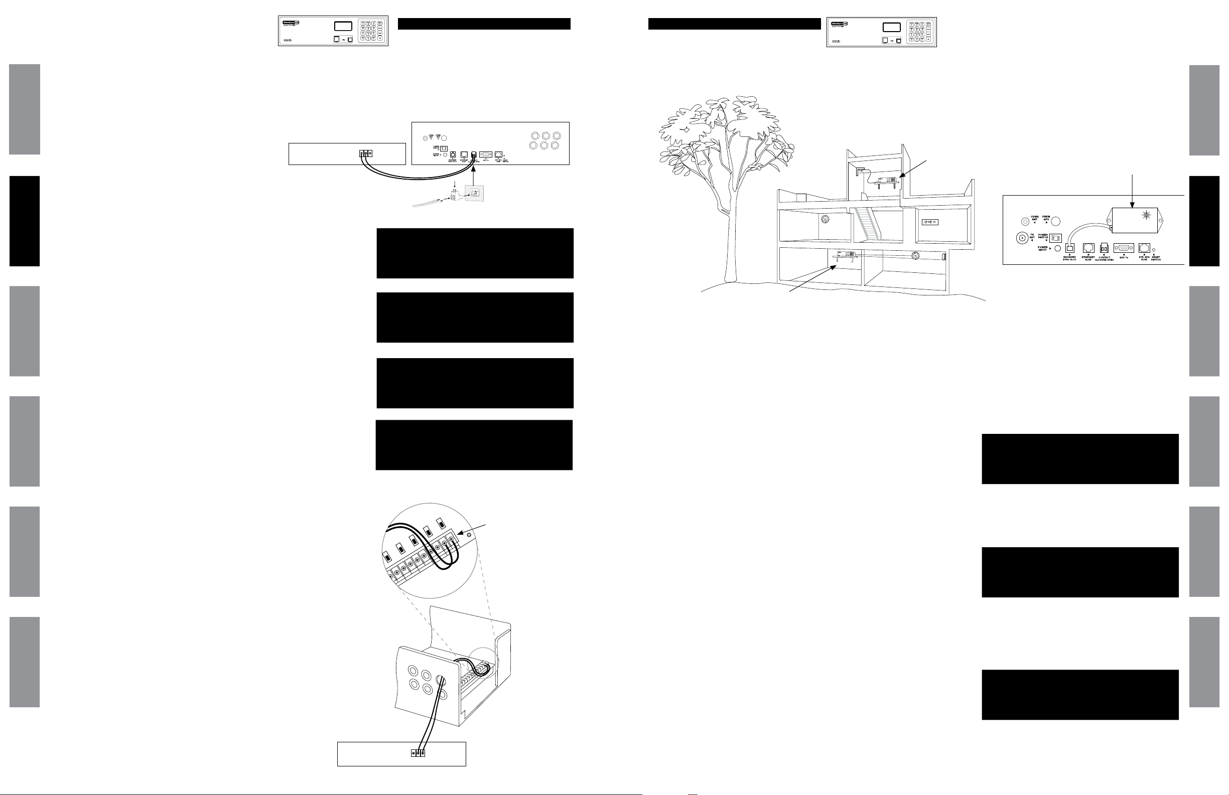
Safety Precautions
Responsible Party: American Time, 140 3rd St. S., PO Box 707, Dassel, MN 55325-0707 USA
TEL: 320-275-2101, declares that the product(s):
SiteSync IQ System Controller and Analog Clocks
Comply with Part 15 of the FCC Rules. Operation is subject to the following two conditions:
(1) This device may not cause harmful interference
(2) This device must accept any interference received, including interference that may cause undesired operation
This equipment has been tested and found to comply with the limits for a Class B digital device, pursuant to Part 15 of the FCC Rules.
These limits are designed to provide reasonable protection against harmful interference in a residential installation. This equipment
generates, uses and can radiate radio frequency energy and, if not installed and used in accordance with the instructions, may
cause harmful interference to radio communications. However, there is no guarantee that interference will not occur in a particular
installation. If this equipment does cause harmful interference to radio or television reception, which can be determined by turning
the equipment o and on, the user is encouraged to try to correct the interference by one or more of the following measures:
• Reorient or relocate the receiving antenna
• Increase the separation between the equipment and receiver
• Connect the equipment into an outlet on a circuit dierent from that to which the receiver is connected
• Call the dealer or an experienced radio/TV technician for help
All electrical power and signal wiring connected to the SiteSync IQ System Controller, secondary clocks, signaling devices and
antennas must be installed by qualied persons in conformance with applicable national and local electrical codes. Improper
installation of this equipment can result in lethal electrical shock and re.
Disconnect and lock out electrical power to the unit before removing the wiring compartment cover.
Voltage applied to clock and signal relay contacts must not exceed 250vac.
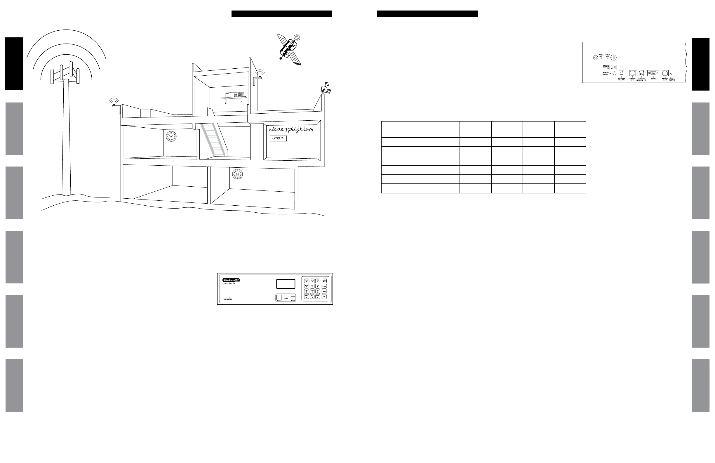
The SiteSync IQ Master should be installed in a secure location protected from:
• Physical damage
• Water, including condensation
• Direct sunlight
• Operation by untrained personnel
Table of Contents
Introduction
System Controller Features .............................................................................................................................................4
Optional System Controller Features..............................................................................................................................5
Installation/Programming Instructions for System Controller
System Controller Installation......................................................................................................................................... 6
System Controller Setup Wizard ................................................................................................................................7-10
Standard GPS Installation ........................................................................................................................................12-13
GPS Plus Installation.................................................................................................................................................14-15
Ethernet Installation .................................................................................................................................................16-17
Contact Closure Sync Installation.................................................................................................................................18
Wireless Sync Installation .............................................................................................................................................19
Wired Clock Circuit Installation.....................................................................................................................................20
Adjust Time Menu ..........................................................................................................................................................21
Wired Signal Circuit Installation.............................................................................................................................. 22-30
Remote Connect Web Interface .............................................................................................................................. 31-39
Settings and Congurations:
Setting Time and Date .................................................................................................................................40
Manage Locks..............................................................................................................................................41
Time Sync Priority........................................................................................................................................41
Clock Code...................................................................................................................................................41
Clear/Restore ...............................................................................................................................................41
Setup Manager.............................................................................................................................................42
Banner Text ..................................................................................................................................................42
Display Settings...........................................................................................................................................42
Auto DST Settings........................................................................................................................................42
USB Flash Drive............................................................................................................................................42
Troubleshooting
System Controller ..........................................................................................................................................................43
GPS .................................................................................................................................................................................44
Ethernet..........................................................................................................................................................................45
Remote Connect.............................................................................................................................................................46
Contact Closure Sync and Wireless Sync .....................................................................................................................47
Wired Clock Circuit ........................................................................................................................................................48
Wired Signal Circuit .......................................................................................................................................................49
Secondary Clocks ..........................................................................................................................................................50
Appendix A: Ethernet Timekeeping - Known Good Internet Time Servers ......................................................................................51
Appendix B: Supported Time Zones...................................................................................................................................................52
Appendix C: Tone Generator Wiring...................................................................................................................................................53
Appendix D: Wired Signal Circuit Programming Examples.........................................................................................................54-56
Appendix E: Checking IQ System Controller Status Information.....................................................................................................57
Appendix F: USB Flash Drive..............................................................................................................................................................58
Appendix G: Port Diagram ..................................................................................................................................................................59
Appendix H: Maintenance Guide........................................................................................................................................................60
Appendix I: Clock Circuit Wiring Diagrams ................................................................................................................................ 61-65
Glossary........... ..................................................................................................................................................................................66-67
American Time
140 3rd Street South, PO Box 707
Dassel, MN 55325-0707
Phone: 800-328-8996
Fax: 800-789-1882
american-time.com

5
© American Time© American Time
4
SiteSync IQ Wired Installation Manual SiteSync IQ Wired Installation Manual
GlossaryAppendix
Troubleshooting
Clock InstallationIntroduction
Glossary Appendix
Troubleshooting
Clock Installation Master Installation Introduction
Introduction Introduction
The American Time SiteSync IQ Wired System oers the latest and most innovative way to incorporate synchronized time
throughout your facility, providing you with improved productivity and punctuality.
SiteSync IQ System Controller Standard Features
The SiteSync IQ System Controller provides synchronized control of system clocks and electrical circuits such as those for
controlling signaling devices and lights. Standard features include:
• Built-in keypad and LCD for setup and operation
• Internal clock accuracy of ±1 minute per year (without synchronization)
• Two level password security
• Automatic Daylight Saving Time and Leap Year correction
• Programmable Custom and Automatic Daylight Saving Time
• Support for time zone clocks (up to eight unique time zones)
The American Time SiteSync IQ wired clock series oers a selection of clocks to match a wide variety of application requirements.
Plastic case, steel case, analog and digital styles will provide years of maintenance-free service.
Master Installation
Model No. Standard
GPS
GPS Plus Ethernet 2-Wire
Sync
SSQMSTR-00XSB X
SSQMSTR-00XSGE X X
SSQMSTR-00XSG X X
SSQMSTR-00XSP X X
SSQMSTR-00XSPE X X
SSQMSTR-00XSE X X
Examples: SSQMSTR-00X6E has 6 signal circuits
SSQMSTR-00X8E has 6 signal circuits and 1 clock circuit
SSQMSTR-00X2E has 1 clock circuit
SiteSync IQ System Controller Optional Features
• Automatic time synchronization with one or more external time references,
including Ethernet and GPS
• Flexible control of 6 signal circuits
• Manual control of signal circuits
The following table shows the options included with each model number. The S in the model number
indicates the number of clock and signal relays (2, 6 or 8) that can be controlled by that model. Add
an R to the end of the Model No. to add the rack mount kit.
abcdefghijklmn
TUE JUL 03 2018
10:38:06 AM USCT
American Time
Status=AUTO ETH=Y
Glossary Appendix
Troubleshooting
Clock
Installation
System Controller
Installation
Introduction
GlossaryAppendix
Troubleshooting
Clock
Installation
System Controller
Installation
Introduction
SiteSync IQ Wired System Controller Specications
Clock Circuit Fuses (2): ......... 8 amps, 250vac, subminiature
Signal Circuits (6):................. Dry contacts rated at 240vac,
............Continuous: 7.5 amps resistive, 5 amps inductive,
............50% duty cycle*: 10 amps resistive
Physical Dimensions:............ 5"h x 167/8"w x 8"d
Temperature Range: ............. 32˚-140˚F (0˚-60˚C)
Mounting: .............................. Desktop or rack mount
Communication:.................... Ethernet, RS-422 (GPS Plus) ,
................................................ RS-232 (Std GPS), Contact Closure
(2-wire) Sync
Shipping Weight: .................. 71/2± 1/2 lbs.
Signal Circuits: ...................... 0 or 6 (optional)
Display:.................................. 128 x 64 graphics LCD
Keypad:.................................. 16 button tactile feedback
................................................ membrane switch
*50% duty cycle is dened as all signal relays on for one minute,
o for one minute, repeating
Input Voltage to Power Adapter: .......100-240vac, 50/60 Hz
OutputVoltagefrom PowerAdapter:..........12.0 ±0.6 vdc
Peak Input Power: ..............................10 watts
Nominal Power: ..................................2.5 watts
Fuse: (Input Power).............................8 amps, 250vac, Subminiature
Standby Timekeeping:.......................10 years
Memory/Time Backup: ......................CR2032 lithium battery,
240 mAh capacity
Timekeeping Accuracy:.....................±1minute/yearwithoutcorrection
from GPS or Ethernet time reference
Program Retention: .........................................Unlimited
Programmable Events: ...................................9,999events total
Schedules: .........................................................99 maximum
Signal Duration: .................................Programmable 1-9 seconds or
continuous On
Clock Circuits (2):...............................Dry contacts rated at 250vac,
8 amps resistive, 5 amps inductive
UL Listed....................................................File #E157522

7
© American Time© American Time
6
Glossary Appendix
Troubleshooting
Clock
Installation
System Controller
Installation
Introduction
GlossaryAppendix
Troubleshooting
Clock
Installation
System Controller
Installation
Introduction
SiteSync IQ Wired Installation Manual SiteSync IQ Wired Installation Manual
Surge
Battery+Surge
Back-UPS600
1.5A
System Controller
Installation
System Controller Setup
Wizard
TUE JUL 03 2018
10:38:06 AM USCT
American Time
Status=AUTO ETH=Y
TUE JUL 03 2018
10:38:06 AM USCT
American Time
Status=AUTO ETH=Y
server rack
Glossary Appendix
Troubleshooting
Clock
Installation
System Controller
Installation
Introduction
GlossaryAppendix
Troubleshooting
Clock
Installation
System Controller
Installation
Introduction
Shown with optional rack mount
option, Part No. H004100
1. Choose a suitable location for the System Controller, following the safety precautions on Page 1:
a. Place the System Controller indoors.
b. Locate near an electrical outlet (120vac).
c. Rack or shelf mount.
d. If you have a sync option, review the applicable installation guidelines included in this manual.
2. Connect the cables to the System Controller:
a. Connect the power supply to the POWER INPUT port.
b. Connect the power supply to 110v electrical supply (American Time recommends using surge protector/battery
backup Part # H006238 shown).
3. Turn on the power to the System Controller:
a. Place the rocker switch on the back of the unit to the ON position as shown above.
b. Conrm that the backlit display on the front of the unit lights up and displays text.
4. Follow the Setup Wizard instructions on pages 6-9.
Part #H006238
Programming Procedure
Set Menu DST - LOCAL
Set DST (Auto)
8=Auto 9=Custom
0=Off OK=Accept
Set Menu Bias LOCAL
Enter Time Zone
offset from UTC
+ 11:30 OK=Accept
Set Menu LOCAL
Time Zone Code: 05
99=Custom USCT
<>=Scroll OK=Accept
Config Menu
Choose Service Lock:
xxxx
0000=Disable OK=Done
Config Menu
Choose User Lock:
xxxx
0000=Disable OK=Done
Setup Wizard
1=Enter Now
2=Bypass
3=Disable
Setup Wizard
Transmissions
1-Enable
2=Disable
• Press: 1, and enter 4 digit User Lock or
enter 0000 to disable this feature.
User Lock
■Note: User Lock is the security level used for accessing time/date
and event menus.
• Press O
vEnter 4 digit Service Lock or enter 0000 to disable this feature.
• Service Lock:
■Note: Service Lock is the security level used for accessing
System Controller conguration menus.
• Press O
wSelect local time zone by using the <> keys or enter a
time code from Appendix B. Press Oand skip to y.
If a custom time zone is needed, press 99and Oand
continue to x.
xEnter oset from UTC for Custom Time Zone.
• Use <>to change + to -.
• Press O
ySelect Daylight Saving Time (DST) option.
• Option 8 causes automatic time changes to and from
DST under the changeover dates currently in eect in the
USA at the time of system manufacture.
Press Oand skip to .
• Option 9 allows a custom DST to be entered. Press
Oand skip to z.
• Option 0 turns o DST. Press Oand skip to .
uTo Congure the System Controller:
Setup Wizard Main Screen
5
4
3
2
1
STOP If you chose Auto or O in y, skip to .
If you chose Custom, continue to z.
Turn on the power to the System Controller
The first time the unit is powered up, it will prompt you (See
Setup Wizard Main Screen) to press:
1To use the Setup Wizard
2Bypass the Setup Wizard temporarily
3Disable the Setup Wizard
■Note: Bypassing 2 or Disabling 3 the Setup Wizard will
prompt you to Enable or Disable transmissions.
14
14
14

9
© American Time© American Time
8
SiteSync IQ Wired Installation Manual SiteSync IQ Wired Installation Manual
System Controller
Setup Wizard
System Controller
Setup Wizard
Glossary Appendix
Troubleshooting
Clock
Installation
System Controller
Installation
Introduction
GlossaryAppendix
Troubleshooting
Clock
Installation
System Controller
Installation
Introduction
zDene DST:
• Press 1 to set xed dates and times for the beginning
and end of DST. Skip to .
• Press 2to set months, weeks, weekdays and times
(oating dates) for the beginning and end of DST. Skip
to
.
Select xed dates for DST (START):
• Use <> to scroll start month and day. Press O
to move to the next eld.
• Use <> or keypad to enter the start time. Press
O to move to the next eld.
• Use <> to select AM/PM. Press O to accept.
Select xed dates for DST (END):
• Use <> to scroll end month and day. Press
O to move to the next eld.
• Use <> or keypad to enter the end time. Press
O to move to the next eld.
• Use <> to select AM/PM. Press O to accept.
Select xed dates for DST (BIAS):
• Use keypad to enter bias.
• Use <> to select "+" or "-". Press O to accept.
Select oating dates for DST (START DATE)
• Use <> to scroll week, day and month. Press
O to move to the next eld.
• Use <> on the bias selection to change + and -.
• Use keypad to enter bias. Press O to accept.
Select oating dates for DST (START TIME):
• Use <> or keypad to enter the start time.
• Press O to accept.
Select oating dates for DST (END DATE)
• Use <> to scroll week, day and month. Press O
to move to the next eld. Press O to accept.
Select oating dates for DST (END TIME)
• Use <> to enter the start time. Press O
to move to the next eld.
• Use <> to select AM/PM. Press O to accept.
Programming Procedure (cont)
Set Menu DST - LOCAL
Start of DST:
1st SUN of APR
Bias +1:00 OK=ACPT
Set Menu DST - LOCAL
Start Time:
01:00 AM
<> = AM/PM OK=ACPT
Set Menu DST - LOCAL
End of DST:
Last SUN of OCT
OK=ACPT
Set Menu DST - LOCAL
End Time:
01:00 AM
<> = AM/PM OK=ACPT
Set Menu DST - LOCAL
DST Bias: +00:00
<> = +/- OK=ACPT
Set Menu DST - LOCAL
DST End: SEP 15
End Time: 02:00 AM
<> = AM/PM OK=ACPT
10
11
12
13
9
8
Set Menu DST - LOCAL
DST Start: Mar 30
Start Time: 01:00 AM
<> = AM/PM OK=ACPT
Set Menu DST - LOCAL
Define DST By:
1= Fixed Dates
2=Floating Dates
7
6
For use only when conguring Custom DST settings
11
12
13
Programming Procedure (cont)
To set the time display mode for the System Controller,
select 12/24 Hr Mode.
• Press 1for 12 hour mode-AM/PM (1:00 PM)
• Press 2for 24 hour mode-Military (13:00)
If the System Controller has {Ethernet + GPS} as sync options, skip to .
If the System Controller has the {Ethernet only,} skip to .
If the System Controller has the {GPS only}, skip to .
If System Controller has no sync options, skip to .
15
17
28
STOP
Set Menu 12/24 Mode
Choose Mode: 1
1=12 HR (AM/PM)
2=24 HR (Military)
14
14
27
To congure unit sync options:
• Press 1to skip to .
• Press 2to skip sync option setup. Please ensure the proper time and
date on the unit.
To set Time Sync Priority:
• For system controllers with more than one sync option congured,
choose the sync option priority.
16 Setup Wizard
Setup Sync Options
1=Yes
2=No
Config Menu
Time Sync Priority
1=(GPS)
2=Ethernet
16
15
15
16
STOP If the System Controller has {GPS only}, skip to .
27
TUE JUL 03 2018
10:38:06 AM USCT
American Time
Status=AUTO ETH=Y
TUE JUL 03 2018
10:38:06 AM USCT
American Time
Status=AUTO ETH=Y
20
19
18
17
Use the keypad to Enable DHCP or Disable to select static IP entry.
• Press 1for enable DHCP
• Press 2for disable DHCP
• Press Oto accept
If you chose enable, skip to
If you chose disable continue to
Use the keypad to enter the Unit IP Address. This is a static address
assigned by your Network Administrator. Enter preceding zeros as
necessary.
• Unit IP Address:
• Press
O
Use the keypad to enter the Subnet Mask. This is the subnet mask of your
network. Enter preceding zeros as necessary.
• Subnet Mask:
• Press O
Use the keypad to enter the Gateway IP. This is the IP address of your
network's Gateway device. Enter preceding zeros as necessary.
• Gateway IP:
• Press O
17
18
18
19
20
22
Comm Menu
Unit IP Address
192.168.001.001
<=Bksp OK=Done
Comm Menu
DHCP
1=Enable
2=Disable OK=Done
Comm Menu
Unit Subnet Mask
255.255.255.000
<=Bksp OK=Done
Comm Menu
Enter Gateway IP
192.168.010.099
<=Bksp Ok=Done

11
© American Time© American Time
10
SiteSync IQ Wired Installation Manual SiteSync IQ Wired Installation Manual
Use the keypad to enter the DNS IP. This is the IP address of your network's DNS
server. Enter preceding zeros as necessary.
• DNS IP:
• Press O
Use the keypad to use Manual IP's or a DNS IP for the same server.
• Press 1for Manual IP
• Press 2for DNS IP
Press Oto accept
If you choose Manual IP, continue to
If you choose DNS IP, skip to
Use the keypad to enter the Time Server address. Enter preceding
zeros as necessary.
• Time Server Address:
• Press O
OR Press O to accept the default set at the factory from the list of known
good Internet Time Servers in Appendix A.
Use the keypad to enter the Alternate Time Server address. Enter preceding
zeros as necessary.
• Alt. Time Server Address:
• Press O
OR Press O to accept the default set at the factory from the list of known
good Internet Time Servers in Appendix A.
This shows the currently selected time server DNS address.
Use Remote Connect to change this value (see page 37).
• Press O
The unit will prompt you to enter the Port Number. This is
remote web access and should be set to 0080.
• Port Number: 0080
• Press O to accept the default (80) set at the factory
To conrm proper set up, sync each option.
• Press 8to sync.
• a. If successful "Sync Successful" will display.
• b. If not successful, "Sync Failed" will display.
Refer to the troubleshooting guide.
• Press
Oto exit the Sync Now function.
Screen 28 will be displayed when the Setup Wizard has been completed. You will no
longer be prompted on power-up for the setup information.
The System Controller should now show the correct time and date on its display screen.
Your System Controller is now set up for proper operation.
You can continue to the other sections of this manual for further information on other
features. If you have any questions or problems that cannot be resolved by following the
steps in the Troubleshooting Guide, please contact Technical Support at American Time
(800-328-8996).
System Controller Setup
Wizard
Glossary Appendix
Troubleshooting
Clock
Installation
System Controller
Installation
Introduction
User Notes
GlossaryAppendix
Troubleshooting
Clock
Installation
System Controller
Installation
Introduction
TUE JUL 03 2018
10:38:06 AM USCT
American Time
Status=AUTO ETH=Y
TUE JUL 03 2018
10:38:06 AM USCT
American Time
Status=AUTO ETH=Y
Programming Procedure (cont)
21
21
22
23
Comm Menu
Enter DNS IP
008.008.008.008
<=Bksp OK=Done
22
23
24
25
26
27
28
Comm Menu
Time Server Entry
1=Manual IP
2=(DNS IP) Ok=Done
Comm Menu
Time Server Address
131.107.013.100
<=Bksp OK=Done
23
25
24
25
Comm Menu
Alt Time Srvr Addr
173.014.055.009
<=Bksp Ok=Done
Time Server DNS
3.americantime.pool
.ntp.org
Ok=Next
Comm Menu
Enter Port Number
for web access: 80
OK=Done
26
Set Menu
Ethernet Sync
Failed
Set Menu
Ethernet Sync
Successful
Set Menu
Time Sync Option is
Available: Ethernet
8=Sync now OK=Set
27b (example)
27a (example)
27 (example)
Setup Wizard
Successfully Completed

13
© American Time© American Time
12
SiteSync IQ Wired Installation Manual SiteSync IQ Wired Installation Manual
Standard GPS Option Standard GPS Option
Mounting and Connecting Standard GPS Receiver
uFor best results, mount the GPS antenna to an
outside wall or to a mast on the roof with a clear view of
the sky.
a. The location should be unobstructed by trees,
branches, power lines and other buildings, etc.
b. Avoid installing the GPS antenna near high power
transmitting antennas.
c. To avoid lightning strikes, the location should not
be the highest point and such that any lightning
rods are well above the antenna.
d. The GPS antenna is environmentally sealed,
but in colder climates, mount the antenna high
enough to avoid getting buried by snow or ice.
e. While not ideal, skylights or windowsills are
possible locations. Avoid installation behind Low-
Emissivity (Low-E) glass as the GPS signal has
diculty penetrating such glass.
vInstall included mounting bracket
a. Allows for mounting on the side of a building or
other structure
b. It is recommended not to mount where there is
excessive roof overhang
wConnect cables to System Programmer
a. Connect GPS receiver cable to STD GPS RJ45 port.
■Note: The GPS unit can be extended up to 100 ft.. with optional
extension cables. See list below.
Optional Extension Cables:
Part # H001840 - 25 ft.
Part # H001841 - 50 ft.
Part # H001842 - 75 ft.
Part # H001846 - 100 ft.
WARNING: Avoid extending outdoors as connectors may
corrode.
2
3
Programming Procedure
GPS Time Menu
Choose:
1=Signal Status
2=Enable/Disable
Set Menu Mode
Enter User Lock:
xxxx
PROG=EXIT OK=ENTER
Set Menu Mode
Time Sync Option is
Available: GPS
8=Sync now OK=Set
GPS Time Menu NOW
Satellites: 3
01-08-2014 1:04:59A
USCST OK=Next
GPS Time Menu
Signal Not Received
01-06-2014 12:28:15A
1 = Last Good OK=Done
uTo conrm GPS signal, press P5:
a. Press: 1, to check signal status.
b. If no signal was received, reference the
troubleshooting guide.
c. The Last Signal Received and the Last Attempted
Reception may be displayed by pressing <or >.
d. Press: O, if signal was received to view number of
connected satellites.
■Note: If you see the number of satellites in view, press
OBBto return to the Main Screen.
If 0 satellites are connected, reference the troubleshooting
guide.
■Note: Allow GPS to synchronize. The time may be incorrect
while the GPS is receiving its signals. This may take up to 25
minutes. After synchronization, the time and the satellites
connected will be updated.
vTo sync System Controller with correct time & date:
a. Press: P1, to Set Menu Mode.
b. Enter User Lock and press O.
c. Press: 9, to sync the System Controller with
GPS. Press >until GPS option is chosen.
d. Press 8to sync with GPS.
■Note: If "GPS Sync Successful" is displayed, press
OBBto return to Main Screen.
If "GPS Sync Failed" is displayed, reference the troubleshooting
guide.
The GPS sync option is now congured and will update the time
on the System Controller automatically once each hour at a time
preset at the factory.
■Note: When GPS synchronization is working, GPS=S will be
displayed on the screen in small text mode as shown in screen
shot 3. If a synchronization attempt fails, GPS=N will be
displayed.
2b
2c and d
1d
1a
GPS Time Menu LAST
Attempted Reception
01-06-2014 12:28:15A
< = Last Good OK=Next
GPS Time Menu LAST
Signal Last Received
01-06-2014 12:28:15A
> = Last Try OK=Next
1c
1c
1b
Standard GPS Option Includes:
a. GPS Receiver with 15 ft. cable
b. Mounting Bracket
■Note: This option automatically syncs once
per hour at a time preset at the factory.
!
Not recommended.
Recommended.
This option provides time synchronization via the Global Positioning System
(GPS). 15 ft. GPS cable can be extended up to 100 ft. with extensions.
Glossary Appendix
Troubleshooting
Clock
Installation
System Controller
Installation
Introduction
GlossaryAppendix
Troubleshooting
Clock
Installation
System Controller
Installation
Introduction
uTurn on the power to the System Controller
a
b
100 ft. max.
75 ft. 15 ft.
RJ45
25 ft.
MON MAR 10 2014
10:30:06 AM USCT
American Time
Status=AUTO GPS=S
3
TUE JUL 03 2018
10:38:06 AM USCT
American Time
Status=AUTO ETH=Y
TUE JUL 03 2018
10:38:06 AM USCT
American Time
Status=AUTO ETH=Y

15
© American Time© American Time
14
SiteSync IQ Wired Installation Manual SiteSync IQ Wired Installation Manual
GPS Plus Option GPS Plus Option
uFor best results, mount the GPS antenna to an outside wall or
to a mast on the roof with a clear view of the sky.
a. The location should be unobstructed by trees,
branches, power lines and other buildings, etc.
b. Avoid installing the GPS antenna near high power
transmitting antennas.
c. To avoid lightning strikes, the location should not be
the highest point and such that any lightning rods are
well above the antenna.
d. The GPS antenna is environmentally sealed, but in
colder climates, mount the antenna high enough to
avoid getting buried by snow or ice.
e. While not ideal, skylights or windowsills are
possible locations. Avoid installation behind Low-
Emissivity (Low-E) glass as the GPS signal has
diculty penetrating such glass.
vAntenna Installation
a. Installation on included mounting bracket
1. Allows for mounting on the side of a building
or other structure.
2. It is recommended not to mount where there is
excessive roof overhang.
b. Installation if using a mast
■Note: If using a mast, it must be grounded.
1. If using a mast, it should be made from 1 inch
schedule 40 pipe, or any rigid tubing or
conduit with an outside diameter of 1.5 inch or
less.
2. Use the U-bolt, hex nuts & lock washers
supplied to x the mounting bracket to the mast.
wConnect cables to System Programmer
a. Connect GPS receiver cable to PREM GPS RS-422
port.
■Note: 50 ft. extension cables, Part #H000818, can be added
between the cable provided and the System Controller. The
cable provided with the kit should always be installed to the GPS
antenna pigtail. The total length of all cables should not exceed
1500 ft., (up to 30 standard extension cables).
Mounting and Connecting GPS Plus Receiver Programming Procedure
GPS Plus Option Includes:
A. Premium GPS Receiver
B. Antenna Mounting Kit
C. 50 ft. Cable
D. Shrink Tubing
■Note: This option automatically syncs once per
hour at a time preset at the factory.
This option provides time synchronization via the Global Positioning
System (GPS). The option includes weather-tight, non-corrosive
connections for outdoor installation and can be extended further (up
to 1500 ft.) than the Standard GPS option.
Recommended
Glossary Appendix
Troubleshooting
Clock
Installation
System Controller
Installation
Introduction
GlossaryAppendix
Troubleshooting
Clock
Installation
System Controller
Installation
Introduction
GPS Time Menu
Choose:
1=Signal Status
2=Enable/Disable
Set Menu Mode
Enter User Lock:
xxxx
PROG=EXIT OK=ENTER
Set Menu Mode
Time Sync Option is
Available: GPS
8=Sync now OK=Set
GPS Time Menu NOW
Satellites: 3
01-08-2014 1:04:59A
USCST OK=Next
GPS Time Menu
Signal Not Received
01-06-2014 12:28:15A
1 = Last Good OK=Done
uTo conrm GPS signal, press P5:
a. Press: 1, to check signal status.
b. If no signal was received, reference the
troubleshooting guide.
c. The Last Signal Received and the Last Attempted
Reception may be displayed by pressing <or >.
d. Press: O, if signal was received to view number of
connected satellites.
■Note: If you see the number of satellites in view, press
OBBto return to the Main Screen.
If 0 satellites are connected, reference the troubleshooting
guide.
■Note: Allow GPS to synchronize. The time may be incorrect
while the GPS is receiving its signals. This may take up to 25
minutes. After synchronization, the time and the satellites
connected will be updated.
vTo sync System Controller with correct time & date:
a. Press: P1, to Set Menu Mode.
b. Enter User Lock and press O.
c. Press: 9, to sync the System Controller with
GPS. Press >until GPS option is chosen.
d. Press 8to sync with GPS.
■Note: If "GPS Sync Successful" is displayed, press
OBBto return to Main Screen.
If "GPS Sync Failed" is displayed, reference the troubleshooting
guide.
The GPS sync option is now congured and will update the time
on the System Controller automatically once each hour at a time
preset at the factory.
■Note: When GPS synchronization is working, GPS=S will be
displayed on the screen in small text mode as shown in screen
shot 3. If a synchronization attempt fails, GPS=N will be
displayed.
2b
2c and d
1d
1a
GPS Time Menu LAST
Attempted Reception
01-06-2014 12:28:15A
< = Last Good OK=Next
GPS Time Menu LAST
Signal Last Received
01-06-2014 12:28:15A
> = Last Try OK=Next
1c
1c
1b
Turn on the power to the System Controller
MON MAR 10 2014
10:30:06 AM USCT
American Time
Status=AUTO GPS=S
3
TUE JUL 03 2018
10:38:06 AM USCT
American Time
Status=AUTO ETH=Y
TUE JUL 03 2018
10:38:06 AM USCT
American Time
Status=AUTO ETH=Y
3
2b
!
Not recommended
1500 ft. max.
50 ft. 1.5 ft.50 ft.50 ft.
A
B
C
D

17
© American Time© American Time
16
SiteSync IQ Wired Installation Manual SiteSync IQ Wired Installation Manual
Ethernet Option Ethernet Option
Glossary Appendix
Troubleshooting
Clock
Installation
System Controller
Installation
Introduction
GlossaryAppendix
Troubleshooting
Clock
Installation
System Controller
Installation
Introduction
TUE JUL 03 2018
10:38:06 AM USCT
American Time
Status=AUTO ETH=Y
TUE JUL 03 2018
10:38:06 AM USCT
American Time
Status=AUTO ETH=Y
Connecting Ethernet Option
Ethernet Option requires:
1. TCP/IP Network with Internet access or connection to a
Network Time Server.
2. Cat 5 or above patch cable (not included).
3. Hostname:
■Note: *Record the last 6 digits of device Serial number
(located on back of system controller) after the asterisk (*).
The Hostname can be used to identify the system controller
on the network for DHCP.
■Note: The default ethernet settling has DHCP enabled
to automatically obtain an IP address from a DHCP server.
If no DHCP address is received, the device will default to
192.16 8.10.10.
4. *Unit IP Address from
Network Administrator:
5. *Subnet Mask:
6. *Gateway IP Address:
7. *DNS Server IP Address:
*Not required if DHCP is Enabled
8. Port Number (defaulted to 80):
9. Time Server DNS Address:
10. Time Server IP Address:
11. Alternate Time Server Address:
See Appendix A for a list of Internet Time Server addresses
(or use the address of a server on your local network)
■Important Note: Time Servers provide time sync for UTC
Time, but do not set Time Zone or DST settings.
■Note: This option automatically syncs once per hour at a
time preset at the factory.
ssiq*
This option provides time synchronization via Simple Network Time Protocol (SNTP) or Daytime Protocol from Internet Time Servers or an
internal Network Time Server.
Timeserver on the Internet
supporting SNTP
or Daytime Protocol
Public
Internet
Computers on the Local Area Network
SiteSync IQ with
Static IP Address
Firewall with Port
123 or 13 open
Gateway
Outside the
facility
Inside the facility
Local Area
Network
Configuration 1: Receive Time Sync via the Internet
(SNTP or Daytime Protocol)
Computers on the Local Area Network
SiteSync IQ with
Static IP Address
Timeserver on the
LAN supporting
SNTP Protocol
Local Area
Network
Outside the facility
Inside the facility
Configuration 2: Receive Time Sync via the Internal
Network (SNTP)
Programming Procedure - Keypad
uCongure Communication (Comm) Settings:
Press P, 7, 3 to access Comm Settings:
a. Use the keypad to Enable DHCP or Disable to select static IP entry.
• Press 1for enable DHCP
• Press 2for disable DHCP
• Press Oto accept
• If 1skip to f
b. Use the keypad to enter the Unit IP Address. This is a static address assigned by your
Network Administrator. Enter preceding zeros as necessary.
• Press O
c. Use the keypad to enter the Subnet Mask. Enter preceding zeros as
necessary. This is the subnet mask of your network.
• Press O
d. Use the keypad to enter the Gateway IP. Enter preceding zeros as
necessary. This is the IP address of your network's Gateway device.
• Press O
e. Use the keypad to enter the DNS IP. Enter preceding zeros as necessary. This is the IP
address of your network's DNS server. Press O.
f. Use the keypad to use Manual IP's or a DNS IP for the time server.
• Press 1for Manual IP
• Press 2for DNS IP
• Press O to accept
Note: If 2, skip to i.
g. Use the keypad to enter the Time Server Address. Enter
preceding zeros as necessary. Press O.
OR Press O to accept the default set at the factory from the list of
known good Internet Time Servers in Appendix A.
h. Use the keypad to enter the Alternate Time Server Address.
Enter preceding zeros as necessary. Press O. Skip to j.
OR Press O to accept the default set at the factory from the list of
known good Internet Time Servers in Appendix A.
i. This shows the currently selected Time Server DNS address. Use Remote Connect to
change this value (see page 37). PressO.
j. The unit will prompt you to enter the Port Number. This is for
Remote Connect web access and should be set to 0080.
Press O to accept the default (80) set at the factory.
k. Press: OBB, to return to Main Screen.
vSync System Controller with correct time & date:
a. Press: P1, to Set Menu Mode.
b. Enter User Lock and press O.
c. Press: 9, to sync the System Controller with Ethernet. Press >until
Ethernet option is chosen.
d. Press 8to sync with Ethernet.
■Note: If "Ethernet Sync Successful" is displayed, press OBB to return to Main Screen.
If "Ethernet Sync Failed" is displayed, reference the troubleshooting guide.
wThe Ethernet sync option is now congured and will update the time on the System Controller
automatically once each hour at a time preset at the factory.
■Note: When Ethernet synchronization is working, ETH=S will be displayed on the screen in small
text mode as shown in screen shot 3. If a synchronization attempt fails, ETH=N will be displayed.
GlossaryAppendix
Troubleshooting
Clock
Installation
System Controller
Installation
Introduction
Turn on the power to the System Controller
■Note: These settings may already have been entered using the Startup
Set Menu Mode
Enter User Lock:
xxxx
PROG=EXIT OK=ENTER
Set Menu Mode
Time Sync Option is
Available: Ethernet
8=Sync now OK=Set
2b
2c
& d
MON MAR 10 2014
10:30:06 AM USCT
American Time
Circts=Auto ETH=S
3
Comm Menu
Unit IP Address
192.168.001.001
<=BkSp OK=Done
Comm Menu
Enter Subnet Mask
255.255.255.000
<=BkSp OK=Done
Comm Menu
Time Server Address
137.107.013.100
<=BkSp OK=Done
Comm Menu
Enter Port Number
for web access:0080
OK=Done
Comm Menu
Enter Gateway IP
192.168.010.099
<=BkSp OK=Done
1j
1d
(ex.)
1c
(ex.)
1g
(ex.)
1b
(ex.)
1a
Comm Menu
DHCP
1=Enable
2=Disable Ok=Done
1h
(ex.)
Comm Menu
Alt Time Srvr Addr
173.014.055.009
<=Bksp Ok=Done
1e
(ex.)
Comm Menu
Enter DNS IP
008.008.008.008
<=Bksp OK=Done
1f
Comm Menu
Time Server Entry
1=Manual IP
2=(DNS IP) Ok=Done
1i
(ex.)
Time Server DNS
3.americantime.pool
.ntp.org
Ok=Next

19
© American Time© American Time
18
SiteSync IQ Wired Installation Manual SiteSync IQ Wired Installation Manual
Contact Closure
Sync Option
Wireless Sync Option
Turn on the power to the System Controller
uSet the SiteSync IQ System Controller to be a transmitter (Tx) of the
contact closure. Press P9 to enter Master to Master Menu.
vEnter User Lock. Press O.
wa. Press 1to set the SiteSync IQ System Controller to Tx.
b. Enter transmit duration in milliseconds (0-9999). Press O.
Example: 2,000ms=2 seconds
xUsing the keypad, set the time when the contact closure should
occur. Use <>to select AM or PM. Press O.
■Note: Reference existing equipment instruction manual for contact
closure time. These closure time and duration settings are also used for the
wireless Master Synchronizer (optional, ATS Part # H004228).
■Important Note! The Sync Time set in Step 4 must be the same for both
units.
Turn on the power to the System Controller
uTo set the SiteSync IQ System Controller to be a receiver (Rx) of the
contact closure. Press P9 to enter Master to Master Menu.
vEnter User Lock. Press O.
wa. Press 2to set the SiteSync IQ System Controller to Rx.
xUsing the keypad, set the time when the existing equipment
performs a contact closure. Use <>to select AM or PM.
Press O.
■Note: Reference existing equipment instruction manual for contact
closure time.
Comm Menu MTM Sync
Transmit Duration:
50 ms
OK=Done
Comm Menu MTM Sync
Master to Master:
1=Tx 3=Off
2=Rx
Comm Menu MTM Sync
Sync Time:
12:00:00 AM
<>AM/PM OK=Done
Comm Menu
Enter User Lock:
____
PROG=Exit OK=Enter
4
3a
3b
2
Existing Equipment Providing 2 Wire Synchronization
SiteSync IQ System Controller providing 2 Wire
Synchronization (refer to screen shots above)
Installing Contact Closure Sync Option
This option allows a SiteSync IQ System Controller to be synchronized with existing equipment with a contact closure. This type of
synchronization can also be implemented between two SiteSync IQ System Controllers.
existing equipment
Transmitting IQ System Controller
COMNO NC NCCOMNO NO COM COMNO NO COM NO COM NO COM
CLOCK 1 CLOCK 2 BELL 1 BELL 2 BELL 3 BELL 4 BELL 5 BELL 6
NO COM
Input
Contact Closure
Output (Circuit 6)
Note: Circuit 6 will not
be operable for use as
a signal circuit when
Tx synchronization is
enabled.
Glossary Appendix
Troubleshooting
Clock
Installation
System Controller
Installation
Introduction
GlossaryAppendix
Troubleshooting
Clock
Installation
System Controller
Installation
Introduction
existing equipment
existing equipment
Rx IQ System Controller
Transmitting IQ System Controller
surge protector switch
NC NCCOMNO NO COM COMNO NO COM NO COM NO COM
CLOCK 2 BELL1 BELL 2 BELL 3 BELL 4 BELL 5 BELL6
NO COM
Input
Contact Closure
Output
Input Connection
1
2
3
Programming Procedure
This option uses the existing system with contact closure
(i.e. Phone/Intercom System, Master Clock, Synchronizer,
etc.) to synchronize a SiteSync IQ System Controller.
Connect wiring as shown in the diagram at right.
This option uses a SiteSync IQ System Controller to sync existing
equipment supporting contact closure input. Connect wiring as shown in
the diagram below.
TUE JUL 03 2018
10:38:06 AM USCT
American Time
Status=AUTO ETH=Y
TUE JUL 03 2018
10:38:06 AM USCT
American Time
Status=AUTO ETH=Y
abcdefghijklmn
For installations with existing wired signal devices in locations remote to the SiteSync IQ System Controller. This involves a
second, wired IQ System Controller in an area remote to the wireless IQ System Controller.
■Note: Requires reception from wireless transmitting SiteSync IQ System Controller.
Example application: The wireless transmitting system controller (A) is on top of the building for best signal coverage, and the wired devices
(clocks, bells, etc.) terminate on a lower oor (B) or area not near the transmitting unit.
Programming Procedure
A: Transmitting SiteSync
IQ System Controller
B: Receiving SiteSync
IQ System Controller
Set Menu Mode
Enter User Lock:
xxxx
PROG=EXIT OK=ENTER
Set Menu Mode
Time Sync Option is
Available: WLS
8=Sync now OK=Set
To sync Receiving System Controller with correct time & date:
uConrm Transmitting SiteSync IQ system controller (A) is
powered and transmitting.
vPress: P1, to Set Menu Mode.
wEnter User Lock and press O.
xPress: 9, to sync the receiving (B) System Controller.
yPress >until WLS option is chosen.
zPress 8to sync time.
■Note: If "WLS Sync Successful" is displayed, press OBBto
return to Main Screen.
If "WLS Sync Failed" is displayed, reference the troubleshooting guide.
The Wireless sync option is now congured and will update the
time on the System Controller automatically once each hour
at a time preset at the factory.
■Note: When Wireless synchronization is working, WLS=S will be
displayed on the screen in small text mode as shown in screen shot 7.
If a synchronization attempt fails, WLS=N will be displayed.
3
4, 5 and 6
Turn on the power to the System Controller
MON MAR 10 2014
10:30:06 AM USCT
American Time
Status=AUTO WLS=S
7
Wireless Receiver

21
© American Time© American Time
20
SiteSync IQ Wired Installation Manual SiteSync IQ Wired Installation Manual
Wired Clock Circuit Option
Glossary Appendix
Troubleshooting
Clock
Installation
System Controller
Installation
Introduction
Adjust Time Menu
GlossaryAppendix
Troubleshooting
Clock
Installation
System Controller
Installation
Introduction
Wired Clock Circuit Installation
To install wired clock circuits:
1. Disconnect and lock out power to the SiteSync IQ System Controller and any circuit wiring.
2. Remove the top cover from the System Controller.
a. Remove screws from each side of the cover.
b. Slide the cover up o the base of the unit.
3. Route signal circuit wires into the wiring compartment of the System Controller.
a. Remove knockout(s). See Appendix G for illustration showing knockout locations on the rear side of the unit.
b. Use copper conductors only.
c. Use strain relief connector ttings in the knockout holes to secure the wires.
d. Route the wires into the wiring compartment, leaving enough slack to make all connections to the relay terminals.
4. Connect clock wires to the circuit relay terminals
REAR OF SYSTEM CONTROLLER
COMNO NC NCCOMNO
CLOCK 1 CLOCK 2
12
Clock Circuit Terminals
Circuit LEDs
(red)
See Appendix I on Page 63 for Clock Circuit Wiring Diagram
The Adjust Time menu serves two functions:
1. Manual correction of impulse secondary clocks, and
2. Simple synchronization of the system controller to an external time source.
Adjust Time
Choose:
1=Adjust System Clks
2=Ethernet Sync Now
Adjust System Clocks
1=Calculated Adjust
2=Man. Adjust Impulse
0=Cancel
Calc Clock Adjust
Enter Time Shown
on secondary clocks
00:00
Adjust System Clocks
Manual Adj. Impulsed
>=Advance Clocks
(1 per min) OK=Done
uPress: 9to access the Adjust Time Menu
vPress 1 to enter Adjust System Clocks Menu
wPress 1to bring up the Calculated Adjust screen
Enter the time shown on the secondary clocks (to the nearest minute).
The time entered should be in 12 hour format as AM/PM settings are
irrelevant.
Press O. The time dierence between the secondary clocks and
the system controller is displayed.
Press Oto initiate automatic correction of the secondary clocks
and return to the Adjust Time screen.
xPressing 2in the Adjust System Clocks menu (#3 at right) brings
up the Manual Adjust screen.
Press
>repeatedly to correct impulse clocks manually.
Press O when nished to return to the Adjust Time menu.
yPressing 2in the Adjust Time screen (#2 above) causes the unit to
attempt synchronization with external time sources* in order of priority.
If successful, a message conrming this ashes before the Time
Display screen appears.
*The time sync priority can be congured. Reference Settings &
Conguration on Page 41.
2
3
3a
4
TUE JUL 03 2018
10:38:06 AM USCT
American Time
Status=AUTO ETH=Y
TUE JUL 03 2018
10:38:06 AM USCT
American Time
Status=AUTO ETH=Y

23
© American Time© American Time
22
Glossary Appendix
Troubleshooting
Clock
Installation
System Controller
Installation
Introduction
SiteSync IQ Wired Installation Manual SiteSync IQ Wired Installation Manual
Glossary Appendix
Troubleshooting
Clock
Installation
System Controller
Installation
Introduction
SiteSync IQ Installation Manual
Wired Signal Circuit Option
Appendix
Troubleshooting
Clock
Installation
System Controller
Installation
Introduction
Programming Events (Keypad Interface)
Wired Signal Circuit Option
The SiteSync IQ System Controller contains 6 integrated signal relays. When congured, the Wired Signal Circuit Option allows the
System Controller to be used for operating bells, tone generators, lighting circuits and other electrical equipment.
■Note: System Controllers with the Ethernet option can also be programmed via the Remote Connect web interface (see page 31).
Denitions:
An Event is programmed into the System Controller with time and date information, as well as a duration or a start/stop command.
For example, Event 0001 may be programmed to execute every Monday, Wednesday and Friday at 10:00 am for 3 seconds.
Each event is assigned to a Schedule. The SiteSync IQ System Controller can store up to 9,999 events. The event duration is
programmable from 1 to 9 seconds and also allows for ON or OFF commands. Normal events are recurring weekday events. A Special
Event contains date information that is not specic to weekdays. For example, you can set a special event for the 4th day of every
month, the 4th day of every January or the 4th day of January in a specic year. You can also set a special event for every Thursday
in January or every Thursday in a specic year.
A Schedule is a group of events. For example, a school might program Schedule 01 with 4 events for their morning Elementary recess
schedule. The SiteSync IQ System Controller allows for 99 unique schedules, with any number of events in each (up to a maximum
total of 9,999 events). Schedules, with groups of events, are assigned to Circuits.
A Circuit is dened as one of the 6 relay outputs on the SiteSync IQ System Controller. Each circuit can be assigned one schedule at
a time. For example, Schedule 01 with 4 events might be assigned to Circuit 1 and Schedule 03 with 10 events might be assigned to
Circuit 2.
vProgramming Recurring Events by Weekday
uProgramming New Events
For a non-special event, this brings up the Event Time screen.
To program start time:
a. Use the number keys to enter the hour and minute. Press<for AM or
>for PM. Press Oto accept the event start time.
The Event Duration screen appears. To program event duration (1-9 seconds):
b. Press any number 1-9to specify duration, or
Press 0to use the default duration(s) for the circuit(s) assigned to the
schedule, or
Press > to latch assigned circuits on until a later event turns them o, or
Press < to turn o assigned circuits that were previously turned on.
Press Oto accept event duration.
a. Press: P2, enter User Lock using the keypad and press O to
enter the Event Menu.
b. Press: 1 to add an event.
c. Select the number of the schedule for the new event and press O.
d. If any events have already been assigned to the selected schedule, the
days and start time for the rst event are displayed. Use the > key to
move to the New Event screen. Press Oto display the Select
Weekdays screen.
■Note: Press < on the rst event to view the last event. Press >to move
to the New Event Screen.
e. To program event days, press 1through7 keys to add or remove
days individually, or
Press 8to add weekdays (shown), 9to add weekends, or
Press 0 for special events. This allows events to be dened by date(s).
Press Oto accept the assigned days.
Event menu
Duration 0=Default
2 Sec (1-9, < or >)
Off=< On=> OK=Set
Event menu
Select event time:
Evt Time: 12:00 AM
MTWTF OK=Acpt
Select Weekdays:
8=M-F MTWTF
9=S+S Key 1234567
0=Special OK=Accept
Event Menu
Sch=10 Event=0000
2014-02-12 12:04 AM
<Scl> M-Del OK-Edt
Event Menu
Choose Schedule
Sch=01 Select 1-99
OK=Accept
Event Menu
View Events by
1=Schedule/Event
2=Dte/Tme 3=WKD
2b
2a
1e
1d
1c
1a and b
GlossaryAppendix
Troubleshooting
Clock
Installation
System Controller
Installation
Introduction
Wired Signal Circuit Installation
To install wired signal circuits (for electrical device control including bells, tone generators, lights, etc.):
1. Disconnect and lock out power to the SiteSync IQ System Controller and any circuit wiring.
2. Remove the top cover from the System Controller.
a. Remove screws from each side of the cover.
b. Slide the cover up o the base of the unit.
3. Route signal circuit wires into the wiring compartment of the System Controller.
a. Remove knockout(s). See Appendix G for illustration showing knockout locations on the rear side of the unit.
b. Use copper conductors only.
c. Use strain relief connector ttings in the knockout holes to secure the wires.
d. Route the wires into the wiring compartment, leaving enough slack to make all connections to the relay terminals.
4. Connect signal wires to the circuit relay terminals.
a. Route the power (feed) line of each circuit to the COM terminal of the desired circuit (1-6) being connected.
b. Route the switched (load) line of each circuit to the NO terminal of the desired circuit (1-6) being connected.
c. Label the wires for each circuit as desired.
■Note: The signal circuits are protected with surge suppression components. In some applications, this protection
can cause leakage current to trigger the output device(s) when the circuit is switched OFF. In these cases, the surge
protection switches (see illustration below) can be moved to the OFF position. Contact American Time Technical Support
with any questions. 800-328-8996.
REAR OF SYSTEM CONTROLLER
12 3 4 5 6
NO COM NO COMCOMNOCOMNONO COM NO COM
SOURCE
220vac
FUSED
WHITE
BLACK
STEP DOWN
TRANSFORMER
LOW VOLTAGE
DEVICES
POWER
Bell 1 Bell 2 Bell 3 Bell 4 Bell 5 Bell 6
nIMPORTANT NOTE: Relay 6 will
be inoperable for running events
when the SiteSync IQ System
Controller is being used to provide
contact closure synchronization
(Tx mode).
Relays
Relay Indicator LEDs
Surge Protection
Switches
Left side
SiteSync IQ System Controller Wiring Compartment Diagram
Typical Signal Circuit
Wiring Diagram
Rear of System Controller
= bell
= light
TUE JUL 03 2018
10:38:06 AM USCT
American Time
Status=AUTO ETH=Y
TUE JUL 03 2018
10:38:06 AM USCT
American Time
Status=AUTO ETH=Y

25
© American Time© American Time
24
SiteSync IQ Wired Installation Manual SiteSync IQ Wired Installation Manual
Wired Signal Circuit Option Wired Signal Circuit Option
Glossary Appendix
Troubleshooting
Clock
Installation
System Controller
Installation
Introduction
GlossaryAppendix
Troubleshooting
Clock
Installation
System Controller
Installation
Introduction
vProgramming Recurring Events by Weekday
(continued)
The Choose Schedule screen reappears:
c. Press
Oto accept the schedule number.
d. The Event Saved screen briey appears followed by the Select Event
Time screen.
e. If a new event is to be programmed with the same assigned schedule,
days and duration as the previous event, Press 1. Enter only the start
time of the new event and press O. Follow this procedure for all new
events sharing the same schedule, days and duration.
To see a programming example, see Appendix D.
Press the 2key to exit this loop and return to the View Events screen at the
top of the Event Menu. Event Menu
Select event time:
Evt Time: 1:00 AM
MTWTF OK=Acpt
2e
Event Menu
Enter Another Event:
1=Yes
2=No
2e
Event Menu
Y=All M=All
MTWTF 05:03 AM
Event 0000 Saved
2d
Event Menu
Choose Schedule
Sch=01 Select 1-99
OK=Accept
2c
TUE JUL 03 2018
10:38:06 AM USCT
American Time
Status=AUTO ETH=Y
TUE JUL 03 2018
10:38:06 AM USCT
American Time
Status=AUTO ETH=Y
a. Press 0in the Select Weekdays.
b. Press 2for Schedule Change.
c. Change the year if necessary or enter 0000 to indicate all years. Press
Obring up the Enter Event Month screen.
d. To change the month, enter the number of the month as 2 digits. Enter
00 to select all months. Press Oto accept and bring up the Choose
screen.
e. Press 1to select a day of the month and bring up the Select Event
Date screen.
f. Enter a 2-digit day of the month or 00 for all days and press O.
Pressing 2in the Choose Screen (4e) brings up the Select Day screen.
At this screen:
Press 1-7keys to add or remove days individually
or Press 8to add weekdays, 9to add weekends.
Press Oto accept the assigned days.
g. The Select Event Time screen appears. To program start time:
Use the number keys to enter hour and minute.
Press <for AM or >for PM.
Press Oto accept the event start time.
xProgramming Schedule Change Events
Event Menu
Choose:
1=Set Date (1-31)
2=Set Weekday(s)
4e
Event Menu
Enter Event Month
Month=02 February
All=00 OK=Accept
4d
Event Menu
1=Special Event
2=Schedule Change
4b
Event Menu
Enter Event Year
Year: 2014 All=0000
OK=Accept
4c
Select Weekdays:
8=M-F MTWTF
9=S+S Key 1234567
0=Special OK=Accept
4a
Event Menu
Select event time:
Evt Time: 12:00 AM
MTWTF OK=Acpt
4g
Event Menu
Select event date
Day of month= 15
All=00 OK=Accept
4f
a. Press 0in the Select Weekdays screen.
b. Press 1for Special Event
c. Change the year if necessary or enter 0000 to indicate all years. Press
Obring up the Enter Event Month screen.
d. To change the month, enter the number of the month as 2 digits. Enter
00 to select all months. Press Oto accept and bring up the Choose
screen.
e. Press 1to select a day of the month and bring up the Select Event
Date screen.
f. Enter a 2-digit day of the month or 00 for all days and press O.
Pressing 2in the Choose Screen (3e) brings up the Select Day screen.
At this screen:
Press 1-7keys to add or remove days individually
or Press 8to add weekdays, 9to add weekends.
Press Oto accept the assigned days.
g. The Select Event Time screen appears. To program start time:
Use the number keys to enter hour and minute.
Press <for AM or >for PM.
Press Oto accept the event start time.
The Event Duration screen appears. To program event duration (1-9 seconds):
h. Press any number 1-9to specify duration
or Press 0to use the default duration(s) for the circuit(s) assigned to the
schedule.
or Press > to latch assigned circuits on until a later event turns them o,
or Press < to turn o assigned circuits that were previously turned on.
Press Oto accept event duration.
Event Menu
Enter Event Month
Month=02 February
All=00 OK=Accept
3d
Event Menu
Enter Event Year
Year: 2014 All=0000
OK=Accept
3c
Select Weekdays:
8=M-F MTWTF
9=S+S Key 1234567
0=Special OK=Accept
3a
wProgramming Special Events
Event Menu
1=Special Event
2=Schedule Change
3b
Event Menu
Choose:
1=Set Date (1-31)
2=Set Weekday(s)
3e
Event Menu
Duration 0=Default
2 Sec (1-9, <or>)
Off=< On=> OK=Set
3h
Event Menu
Select event date
Day of month= 15
All=00 OK=Accept
3f
wProgramming Special Events (continued)
Event Menu
Select event time:
Evt Time: 12:00 AM
MTWTF OK=Acpt
3g

27
© American Time© American Time
26
SiteSync IQ Wired Installation Manual SiteSync IQ Wired Installation Manual
Wired Signal Circuit Option Wired Signal Circuit Option
Reviewing and Editing Events by Date & Time
Reviewing and Editing Events by Weekdays
zReviewing and Editing Events by Schedule (continued)
a. Press: P2, enter User Lock (unless disabled) using the keypad and
press O (unless User Lock is disabled) to enter the Event Menu. From
here:
b. Press 3to access the View Weekday screen.
c. Select the weekday needed by:
Pressing one of the 1-7keys
Use the <and > keys to scroll through screens showing events
scheduled for that day. The steps for reviewing and editing selected events
are the same as those listed in Reviewing and Editing Events by Schedule
with one exception: event number cannot be used to jump directly to an
event.
a. Press: P2, enter User Lock (unless disabled) using the keypad and
press O (unless User Lock is disabled) to enter the Event Menu. From
here:
b. Press
2to access the Chronological Sort screen. The options given are
Sort or Cancel Sort. Either selection will go to the Hour screen (6c):
c. At the Hour screen, indicate the hour to start displaying events in
chronological order. Enter the hour as 2 digits in 24 hour format. Example:
the earliest programmed event is 5:00 AM; entering 05 (or an earlier hour)
and pressing Oleads to screen 6d.
d. Use the <and >keys to scroll backward or forward through all
programmed events. The steps for reviewing and editing selected events are
the same as those listed in Reviewing and Editing Events by Schedule with
one exception: the event number cannot be used to jump directly to an event.
c. This screen shows the start time of the event. To change start time:
Use the number keys to enter hour and minute.
Press
<for AM or >for PM.
Press
Oto accept the event start time. This brings up the Event
Duration screen.
d. To program event duration (1-9 seconds):
Press any number 1-9to specify duration, or
Press 0to use the default duration(s) for the circuit(s) assigned to the
schedule, or
Press > to latch assigned circuits on until a later event turns them o, or
Press
< to turn o assigned circuits that were previously turned on.
Press
Oto accept event duration.
Press Oto save event changes.
To see a programming example, see Appendix D.
Event Menu
Duration 0=Default
2 Sec (1-9, <or>)
Off=< On=> OK=Set
Event Menu
Select event time:
Evt Time: 12:00 AM
MTWTF OK=Acpt
6d
6c
Event Menu Time Sort
MTWTF 05:03 AM
Sch: 01 - Event: 0000
<>=Scroll OK=Edit
Event Menu Time Sort
Hour (24)
<>=Scroll OK=Edit
Event Menu WKD sort
View Weekday: MON
Sch: 01 - Event: 0000
<>=Scroll OK=Edit
Event Menu
View Events by
1=Schedule/Event
2=Dte/Tme 3=WKD
Event Menu
View Events by
1=Schedule/Event
2=Dte/Tme 3=WKD
7d
7c
8b
8a
7a
Glossary Appendix
Troubleshooting
Clock
Installation
System Controller
Installation
Introduction
GlossaryAppendix
Troubleshooting
Clock
Installation
System Controller
Installation
Introduction
TUE JUL 03 2018
10:38:06 AM USCT
American Time
Status=AUTO ETH=Y
TUE JUL 03 2018
10:38:06 AM USCT
American Time
Status=AUTO ETH=Y
zReviewing and Editing Events by Schedule
yReviewing and Editing Events
a. From the "View Events by" screen (4), press 1to select Schedule/Event
screen.
Key in a schedule number and press O. If there are existing events
assigned to the schedule, the days and start time for the lowest numbered
event are displayed.
Use the <and >keys to scroll through screens for all existing events
or enter an event number to move immediately to that event.
Press Bto exit the Event Menu. Press Mto delete the event. Press
Oto view the Select Weekdays screen.
b. This screen shows the days previously assigned to the event. To change
event days:
Press 1-7keys to add or remove days individually, or
Press 8to add weekdays
or Press
9to add weekends
or Press
0to edit a special event (this will lead to the series of screens for
dening special events).
Press Oto accept the assigned day. For recurring events this brings up the
Event Time screen.
Press: P2, enter User Lock (unless disabled) using the keypad and press
O (unless User Lock is disabled) to enter the Event Menu. From here:
Press 1to add, view, edit or delete events sequentially by event number
in a particular schedule, or
Press 2to view, edit or delete events in all schedules, beginning with the
rst event scheduled to start on or after a specied hour, or
Press 3to view, edit or delete events by weekday.
Select Weekdays:
8=M-F MTWTF
9=S-S Key 1234567
0=Special OK=Accept
Event Menu
Sch=01 Event=0000
2014-02-15 12:04 AM
<Scl> M=Del OK=Edt
Event Menu
View Events by
1=Schedule/Event
2=Dte/Tme 3=WKD
6b
6a
5
xProgramming Schedule Change Events (continued)
The Change Schedule screen reappears:
h. Press the 2-digit schedule number of the schedule to change to. Press O
to accept the schedule number.
i. The Event Saved screen briey appears followed by the Enter Another
Event screen.
Press Bexit the Event Menu.
Event Menu
Change Sch 01 To
Sch=02 Select 00-00
OK=Accept
4h
Event Menu
Change Schedule
JUN 02 2014 12:00 AM
Event 0000 Saved
4i

29
© American Time© American Time
28
SiteSync IQ Wired Installation Manual SiteSync IQ Wired Installation Manual
Wired Signal Circuit Option Wired Signal Circuit Option
GlossaryAppendix
Troubleshooting
Clock
Installation
System Controller
Installation
Introduction
Glossary Appendix
Troubleshooting
Clock
Installation
System Controller
Installation
Introduction
vEnabling and Disabling Signal Circuits
uSetting Signal Circuit Schedule and Duration (continued)
a. From the View Circuits screen, press 3to enter the Enable Circuits
screen to view or change the control status of individual circuits.
b. For a signal circuit to be controlled by programmed events, it must be
enabled (on) and the status of the system controller must be set to
AUTO. To set status to AUTO:
Press
8, enter User Lock and press O.
c. Setting the system controller status to OFF disables all signal circuits.
To set the status to OFF:
Press 0, enter the User Lock (unless User Lock is disabled) and press
O(unless User Lock is disabled)
d. This screen shows the current default duration for all circuits. "<"
indicates an o default and ">" indicates an on default. To change the
default duration for a circuit, press the number of the circuit (i.e. 1).
e. The Select Circuit Duration screen shows the current default duration
for the selected circuit. This duration applies only for events that are
programmed with a duration of 0. Circuit duration can be for a denite
period (1-9 seconds) or for a time dened by two successive events. The
rst event turns the circuit on, the second event turns it o. To change
circuit default duration:
• Press any number 1-9 to specify duration in seconds, or
• Press
>to latch the circuit on, or
• Press < to latch the circuit o.
Pressing any of these options saves the circuit duration and returns to
the View Circuits screen (a).
To see a programming example, see Appendix D.
Circuit Menu
Select Cir 1 Duration
5 Sec (1-9, <or>)
Latchin Off=< On=>
Circuit Menu
Select Circuit:
Cir 1 2
Dur < 1
1e
1d
Circuit Menu
Enable Cir: OK=Done
1=On 2=On 3=On
4=On 5=On 6=On
Circuit Menu
View Circuits for:
1=Schedule 3=On/Off
2=Duration Prog=Exit
2b
2a
TUE JUL 03 2018
10:38:06 AM USCT
American Time
Status=AUTO ETH=Y
TUE JUL 03 2018
10:38:06 AM USCT
American Time
Status=AUTO ETH=Y
Programming Signal Circuits (Keypad Interface)
Optional signal relays for controlling signal or lighting circuits must be assigned to schedules of events for automatic control. Multiple
circuits can be assigned to one schedule, but each signal circuit can be assigned to only one schedule.
Each signal circuit is also programmed with a default event duration. This allows dierent signal circuits assigned to the same schedule to
be activated for dierent lengths of time for the same event. For example, a school may have circuit 1 connected to the elementary bells and
wish to ring those for 3 seconds. It may have circuit 2 connected to the middle school bells and wish to ring those for 5 seconds. The same
events can be assigned to a single schedule but will have dierent durations on dierent circuits when using circuit duration defaults. This
default duration can be overridden by the duration specied for an event (described in the Programming Events section).
■Note: System Controllers with the Ethernet option can also be programmed via the Remote Connect web interface (see page 31).
Signal Circuit Menu
From Program
Menu
User Lock
Enable
Circuits
Select
Circuit
Select
Duration
1-9, < or >
Select
Schedule
Select
Circuit
Exit to Main
Screen
View Circuits
1=Schedule 3=On/Off
2=Duration
3
3
2 1-6
1-61
OK
PROG
OK
OK
OK
nNote: To return to the View
Circuits screen from any of these
screens, press the Bbutton.
uSetting Signal Circuit Schedule and Duration
a. Press P3. Enter User Lock (unless User Lock is disabled) and
Press O(unless User Lock is disabled) to enter Circuit Menu.
b. Press 1to select the Signal Circuit Schedule Assignment screen.
The current schedule assignments for all circuits are shown. To
change the schedule assignment for a circuit, press the number of the
circuit (i.e. 1).
c. Assign a schedule to this circuit by pressing the >or <buttons
until the correct schedule is displayed. (Pressing 0 disables the circuit)
Press Oto accept.
This returns you to the Signal Circuit Schedule Assignment screen (b).
Press B.
Press 2 to bring up the Duration screen.
Circuit Menu
Cir:01 Choose Sch
Sch: 01 00=Special
OK=Accept
Circuit Menu
Select Circuit:
Cir 1 2 3 4 5 6
Sch 01 01 02 02 03 03
Circuit Menu
View Circuits for:
1=Schedule 3=On/Off
2=Duration Prog=Exit
1c
1b
1a

31
© American Time© American Time
30
Glossary Appendix
Troubleshooting
Clock
Installation
System Controller
Installation
Introduction
GlossaryAppendix
Troubleshooting
Clock
Installation
System Controller
Installation
Introduction
SiteSync IQ Wired Installation Manual SiteSync IQ Wired Installation Manual
Glossary Appendix
Troubleshooting
Clock
Installation
System Controller
Installation
Introduction
Remote Connect Web Interface
GlossaryAppendix
Troubleshooting
Clock
Installation
System Controller
Installation
Introduction
The Remote Connect Web Interface allows remote access to your SiteSync IQ system controller via a web browser. This includes Event
and Circuit programming, manual circuit activation, time/date settings and other system congurations.
This feature is available to all SiteSync IQ System Controllers with the Ethernet option.
Note: Java SE Runtime Environment (JRE) 7 Update 7 will need to be installed to run the Events Applet.
–This can also be downloaded at http://www.java.com/en/
–Ensure that you have the most current web browser (ie. Firefox, Internet Explorer, Chrome)
To access Remote Connect:
1. Ensure that the SiteSync IQ System Controller installation has been performed (page 6) and that the Ethernet option has been
congured (pages 18-19)
2. Open a web browser. Enter the IP address for your system controller (#4 on page 18) as http://xxx.xxx.xxx.xxx or ssiq plus last
six digits of MAC address if DHCP is Enabled in the web browser’s Address eld (Figure 1). Press the Enter key.
or
Figure 1
■Note: If using DHCP Host Name, the network or computer connected to the system controller for conguration must be on the same
Subnet for Host Name to work properly.
■Note: If the Remote Transmitter is on a network without a DHCP server, the default address of the Remote Transmitter will be
192.168.10.10. In this situation, directly connect an Ethernet patch cable from the Remote Transmitter to a computer that is on the same
Subnet. Example: Set the connecting computer IP address to 192.168.10.11. See your Network Administrator if you do not know how to
do this.
3. A User Login window, (Figure 2) will appear. There are two available user names, uclock and sclock, which represent the user
and service access levels. The user security level allows access to everything but the Conguration Tab.
User Level Access:
Enter uclock in lowercase letters in the User Name eld and uclock in the Password eld. This is a user login which will allow
access to time/date and event menus.
Service Level Access:
Enter sclock in lowercase letters in the User Name eld and sclock in the Password eld. This is a service login which will
allow access to all menus.
**Passwords may be changed in the Conguration Tab.
Then, click the Login button.
Figure 2
4. The Remote Connect utility will appear with the General tab selected. The tabs displayed may dier depending on the
conguration of the unit.
Figure 3
For more details on the features of Remote Connect, click on the Support link in the upper right-hand corner of the utility (Figure 3).
Wired Signal Circuit Option TUE JUL 03 2018
10:38:06 AM USCT
American Time
Status=AUTO ETH=Y
For circuits congured for ON/OFF operation:
If the default duration for a circuit being activated with the MAN function is currently congured to ON or OFF (in the Circuit Durations
Menu) the circuit will toggle states when pressing the MAN key. This feature can be used to turn on lights after a power outage. For example,
parking lot lighting is set up on Circuit 6 with a continuous ON event at 10:00pm, and an OFF event at 6:00am. The power goes out due to
a thunderstorm at 2:00am and comes back on at 3:00am. These parking lot lights will be o, since the unit was reset. To turn them back on
after 3:00am, you can activate circuit 6 via the MAN button, as described on the previous page. The lights will then stay on until the OFF
event at 6:00am.
Automatically switching assigned schedules for a circuit:
This feature allows for programming of a schedule change on any circuit. This
may be handy for setting a holiday schedule, for example:
To program an automatic schedule change:
1. Press P3, enter User Lock (if applicable), then press 1. The circuit
schedule assignments screen will display.
2. Press circuit (1-6) you wish to set automatic schedule change for.
3. Press Mbutton to enter a schedule change.
4. Option 1and 2are schedule replacements. This allows for reverting
back to the current schedule at a later date.
5. Select 1or 2. In this screen, use the <>keys to select the schedule
to change to. Press O.
6. In this screen, enter the date with the keypad. Press Oafter entry of each
eld to advance. For example, press Oafter entering the year to
advance to the month eld. AM/PM can be selected with the <>keys.
Press Owhen date and time have been entered.
7. Repeat these steps for another schedule change on this circuit. Choose
option 2if option 1was initially set or vice versa. These options will
occur chronologically by the date and time entered for each.
To see a programming example, see Appendix D.
wControlling Signal Circuits Manually
Signal circuits can be controlled manually with the MAN key acting as a momentary push-button switch. To initiate manual control:
a. Press M, enter User Lock (unless User Lock is disabled) and
press O(unless User Lock is disabled).
b. Press any combination of keys 1-6 to select or deselect the circuits to be
turned on with the Mkey.
Wired Circuit Activation:
Press and hold the Mkey to activate the selected circuits for the desired length of time.
Release the Mkey.
■Note: When the wireless circuit activation is enabled, the wired activation will have approximately a 3 second delay to
account for the wireless transmission.
The Mkey can be pressed as many times as needed. Control of the signal circuits reverts to its previous state (AUTO or OFF) upon exiting
this menu.
Wireless Circuit Activation:
Press 0 to enable wireless circuit activation. Press Mto activate the selected circuits for the default duration of circuit 6.
■Note: Reference Setting Signal Circuit Schedule and Duration on Page 29 to change the default duration of circuit 6.
■Note: Upon pressing M, a TX will appear in the upper right hand corner to signify that the wireless activation is being transmitted.
■Note: The wired circuit will be delayed in this mode.
Manual Signal TX
Select Circuits: 0=WL 7=All
Circuit: 1234567
Man=Signal OK=Exit
Circuit Menu
Select Circuits 1
Circ 1 2 3 4 5 6
Sch 01 01 04 -- -- --
Circuit Menu
Circuit 1 : Sch 01
MAN=Timed Sch Change
<>=Scroll Ok=Accept
Circuit Menu
Timed Sch Change for
Circuit 1 : Sch 01
1=Sch05 2=Empty
Time Sched Change to
Sch:05 on 2014-10-31
at 08:00 AM
<>=Scroll OK=Next
Time Sched Change to
Sch:05 on 2014-10-31
at 08:00 AM
<>=AM/PM OK=Next
3b
2
3
4
5
6

33
© American Time© American Time
32
Glossary Appendix
Troubleshooting
Clock
Installation
System Controller
Installation
Introduction
GlossaryAppendix
Troubleshooting
Clock
Installation
System Controller
Installation
Introduction
SiteSync IQ Wired Installation Manual SiteSync IQ Wired Installation Manual
Remote Connect Web Interface
Glossary Appendix
Troubleshooting
Clock
Installation
System Controller
Installation
Introduction
Remote Connect Web Interface
GlossaryAppendix
Troubleshooting
Clock
Installation
System Controller
Installation
Introduction
Impulse – If the system is to operate with impulse clocks and a impulse clock code is selected the Manually Adjust Impulse
Clocks box will appear. For example, setting the Clock Code selector to 2 will enable impulse clock operation.
Figure 6
• The Calculated Adjustment will automatically adjust the impulse clocks to the correct time. Just enter the time that is
shown on the impulse clocks and press Adjust. The number of impulses necessary to adjust the clocks will automatically be
sent to the clocks.
• The Direct Secondary Clock Adjustment will allow for a specic time advancement in minutes. Therefore, entering the
number of minutes of advancement and pressing Adjust will send the corresponding number of impulses to the clocks.
Set Tab:
The Set Tab allows you to set the time zone, daylight saving time, date, and time for your local clocks and time zone clocks.
Figure 7
1. Time: This allows the user to set the time in the following format HH:MM:SS. After selecting a time change, the Update
button must be pressed to take eect.
■Note: Time will always be in military time.
2. Date: This allows the user to set the date. After changing the date, the Update button must be pressed to take eect.
3. On Demand Sync: The synchronization options congured on the system controller will be displayed. The user may choose
the option in which they would like to synchronize their time and press Sync Now. The time and date will be updated
automatically if successful.
indicates a successful sync. indicates a failed sync.
4. System Controller Time Zone Conguration: When this is selected, the Time Zone and Daylight Saving Time settings can be
congured. The Update button in the lower right hand corner must be pressed for any changes to take eect.
—Time Zone: This drop down contains a list of all time zones.
—Daylight Saving Time: This drop down contains AUTO, CUSTOM, or OFF.
5. Time Zone Clock Conguration: There are 8 selectable time zone clocks. Each time zone clock can be congured to a time zone
and DST. The Update button in the lower right hand corner must be pressed for any changes to take eect.
—Time Zone: This drop down contains a list of all time zones.
—Daylight Saving Time: This drop down contains AUTO, CUSTOM, or OFF.
General Tab:
The General Tab contains information about the system controller as well as manual correction options for systems with clock relays.
Figure 4
1. Clock Code – This allows the user to see which clock code is currently selected to run their wired clocks. If the text is cut o, hover
over with mouse to see full text. This eld may not be selectable if the system controller is not congured for clock relays.
2. Circuit Status – This will enable the bell relays if set to AUTO. This eld may not be selectable if the system controller is not
congured for bell relays.
■Note: Scheduled events will not run if this is not set to AUTO.
3. Device Name – This allows the user to name the system controller. This is useful for users that have more than one SiteSync IQ
system controllers to manage.
■Note: Changing the Device Name requires Service-level access.
4. Time Last Set – This will display the last date and time the system controller was set. The source of which the date and time
was set will also be displayed.
■Note: Ethernet 1 is the Primary Ethernet time server and Ethernet 2 is the Alternate time server as seen on Ethernet tab page 43.
5. Software Version – This will display the current software version of the SiteSync IQ system controller.
6. Serial Number – This is the serial number of the SiteSync IQ system controller.
7. Unit Conguration – This is the conguration code of the SiteSync IQ system controller.
8. Model Number – This is the model number of the SiteSync IQ system controller.
9. Call Sign – This is the call sign used by the SiteSync IQ system controller.
10. Previous/Next Signal – This will display the next circuit activation to occur.
11. Last Powered ON – This will display when the SiteSync IQ system controller was last turned on. This is useful to determine if
the unit has lost power.
12. Battery Low – This indicates that the internal timekeeping battery need to be replaced. See Troubleshooting Section page 55
for more information.
Clock Codes:
Synchronous – If the system is to operate with synchronous clocks and the synchronous clock code is selected the Manually
Adjust Synchronous Clocks box will appear. For example, setting the Clock Code selector to 1 will enable synchronous clock
operation.
Figure 5
•Pressing the 1 Hour button will advance the clocks by 1 hour. There will be approximately a 1-2 minute delay for each 1
Hour button press to allow the clocks to adjust.
• Pressing the 12 Hour button will advance the clocks to the congured 12 hour mark. There will be a maximum delay of
13 minutes for each 12 Hour button press to allow the clocks to adjust.

35
© American Time© American Time
34
Glossary Appendix
Troubleshooting
Clock
Installation
System Controller
Installation
Introduction
GlossaryAppendix
Troubleshooting
Clock
Installation
System Controller
Installation
Introduction
SiteSync IQ Wired Installation Manual SiteSync IQ Wired Installation Manual
Remote Connect Web Interface
Glossary Appendix
Troubleshooting
Clock
Installation
System Controller
Installation
Introduction
Remote Connect Web Interface
GlossaryAppendix
Troubleshooting
Clock
Installation
System Controller
Installation
Introduction
Event Tab (cont):
5. Edit: This will prompt the Event Edit window for the event highlighted. This can also be accessed by double clicking on an
entered event.
6. Delete: This will delete the highlighted event.
7. Delete All: This will delete all events.
8. Print: This will print the events that are displayed in the table.
Circuit Tab:
The Circuit Tab contains circuit designations to specic schedules. This tab also contains the Manual Activation feature which allows manual
activation of relays.
Schedule:
Figure 10
1. Enabled: This allows the user to enable or disable the circuit. The circuit must be enabled to run an assigned schedule. The
Update button must be pressed for changes to take eect.
2. Assigned Schedule: This is the current schedule assigned to the circuit. The Update button must be pressed for changes to take eect.
3. Default Duration: This is the default duration of the circuit. Events may or may not use this default duration. The Update
button must be pressed for changes to take eect.
4. Switching 1: This allows the user to schedule a schedule change. For example, the image above may be a typical example of a
winter break schedule. The Update button must be pressed for changes to take eect.
a. Schedule: This is the schedule that the circuit will switch to at the specied date/time.
b. Date/Time: This is the date/time in which the schedule for the circuit will switch.
5. Switching 2: This has the same functionality as Switching 1.
6. Circuit Description: This allows the user to name the circuits. The Update button must be pressed for changes to take eect.
7. Schedule Description: This displays the schedule name as dened in the Event Edit window (Figure 9).
Event Tab:
The Event Tab allows you to create, edit, print, and save your schedules.
Figure 8
1. View: This row is for sorting which events should be displayed in the table below. If Schedule or Day is selected an additional
drop down will appear for selection.
■Note: Press the Refresh button to update the table.
2. Export: This allows the user to export their schedules to an .ats le for backup.
3. Import: This allows the user to import a .ats le.
4. Add: This allows the user to add new events to a specied schedule. There are three types of events:
–Regular Events: A reoccurring day of the week event.
–Special Events: An event that occurs on a specic time and date.
–Schedule Change: A planned change of schedule on a specic time and date.
This will prompt the following:
a. Schedule: The current event schedule.
b. Schedule Name: The name of the selected schedule.
c. Regular Event/Special Event/Schedule Change: The event type.
d. Special Event Date: Specic date selection for Special Events or
Schedule change Events. Does not appear for Regular Events.
Date may not be in the past.
e. Change Schedule To: Schedule selection to change to.
This only appears if a Schedule Change Event is selected.
f. Duration: Duration of event. Does not apply for Schedule Change Events.
g. Time: The specied time of the event.
h. Weekdays (M-F)/Weekends (S-S): Day of the week selector.
i. Accept: Accept event entry.
j. Cancel: Cancel event entry.
Figure 9

37
© American Time© American Time
36
Glossary Appendix
Troubleshooting
Clock
Installation
System Controller
Installation
Introduction
GlossaryAppendix
Troubleshooting
Clock
Installation
System Controller
Installation
Introduction
SiteSync IQ Wired Installation Manual SiteSync IQ Wired Installation Manual
Remote Connect Web Interface
Glossary Appendix
Troubleshooting
Clock
Installation
System Controller
Installation
Introduction
Remote Connect Web Interface
GlossaryAppendix
Troubleshooting
Clock
Installation
System Controller
Installation
Introduction
Manual Activation:
Figure 11
1. Enabled: This allows the user to enable or disable which circuits should be manually activated.
2. Signal Duration: This is the duration which the circuit will manually activate.
—Momentary: The duration Momentary is only used for Wired Signal Activation. This will allow the user to
signal the circuit for as long as they hold down the Wired button.
3. Circuit Description: This is the description of the circuit as assigned in the Schedule Tab.
4. Wired: This will signal the wired enabled circuits only for the duration specied in the Signal Duration.
5. Wireless: This will signal the wireless enabled circuits only for the duration specied in the Signal Duration.
■Note: A Momentary Signal Duration cannot be assigned to a wireless signal activation.
6. Both: This will signal the wired and wireless enabled circuits for the duration specied in the Signal Duration.
■Note: A Momentary Signal Duration cannot be assigned to a wireless signal activation.
Ethernet Tab: (Only editable with Service-level login).
The Ethernet Tab contains the network settings for the SiteSync IQ system controller.
1. Ethernet Enable: This allows the user
to choose if the SiteSync IQ system
controller should be a client, server, or
both (time synchronization).
2. DHCP: This is the default Ethernet
setting. When this box is checked,
the device will automatically obtain an
IP address from a DHCP server. The
address received will be displayed in
the Unit IP Address boxes.
■Note: If no DHCP address is
received, the device will default to
192.168.10.10. In this situation,
directly connect an Ethernet patch
cable from the system controller
to a computer that is on the same
Subnet. Example: Set the connecting
computer IP address to 192.168.10.11.
See your Network Administrator if
you do not know how to do this. More
information is also available in the
Ethernet troubleshooting section.
3. Unit IP Address: This displays the IP address of the system controller. These boxes are normally grayed out and can only be changed if
the DHCP box is unchecked. After changing all IP elds in the Ethernet Tab, press the Update button to save the conguration.
4. Subnet Mask: This displays the subnet mask of the system controller. After changing all IP elds in the Ethernet Tab, press the Update
button to save the conguration.
5. Gateway IP: This displays the assigned Gateway IP. After changing all the IP elds in the Ethernet Tab, press the Update button to save
the conguration.
6. DNS: This displays the IP address of the network server.
7. MAC Address: This displays the MAC address of the SiteSync IQ system controller. This eld can't be changed in
Remote Connect.
8. Port Number: This Port Number is defaulted to 80 so that Remote Connect can be displayed. This enables the web server.
9. Time Server: This displays two time server options, only one can be selected.
10. Time Server IP Address: This displays the IP address of the time server. After changing this eld, press the Update button. This is
referred to as Ethernet 1 which is displayed under the general tab. Time Last Set: (Source Ethernet 1).
11. Alt. Time Server IP Address: This displays an alternate IP address of a time server. After changing this eld, press the Update button.
This is referred to as Ethernet 2 check is displayed under the General tab, Time Last Set: (Source Ethernet 2).
12. Time Server DNS Address: This displays the IP address from a DNS server used for SNTP synchronization (i.e. 0.americantime.pool.ntp.
org or time.nist.gov).
13. History: This displays a history of the Ethernet activity to and from the Remote Transmitter. This can be reset by pressing the Reset
Packets Rx/Tx button.
■Note: When changing these setting in Remote Connect, close your browser and log in again (with the new IP address, if applicable).
Use caution when revising these settings, as you could lose connectivity after pressing Update.
Figure 12
Figure 13

39
© American Time© American Time
38
Glossary Appendix
Troubleshooting
Clock
Installation
System Controller
Installation
Introduction
GlossaryAppendix
Troubleshooting
Clock
Installation
System Controller
Installation
Introduction
SiteSync IQ Wired Installation Manual SiteSync IQ Wired Installation Manual
Remote Connect Web Interface
Glossary Appendix
Troubleshooting
Clock
Installation
System Controller
Installation
Introduction
Remote Connect Web Interface
GlossaryAppendix
Troubleshooting
Clock
Installation
System Controller
Installation
Introduction
Conguration Tab:
The Conguration Tab requires a service password for access. Within this tab, the user can change their passwords, update their rmware,
change their time synchronization priority, or change the system controller’s banner text.
Figure 16
1. Set Auto DST Dates: This allows the user to change the AUTO DST dates and times. This allows for future exibility if the
DST were to change. The Update button must be pressed for changes to take eect.
2. Clock Code – This allows the user to see which clock code is currently selected to run their wired clocks. If the text is cut o, hover
over with mouse to see full text. This eld may not be selectable if the system controller is not congured for clock relays.
3. User Password/Verify: This allows the user to change the User Password. The User Password must match the Verify Password to
be accepted. The Update button must be pressed for changes to take eect.
4. Service Password/Verify: This allows the user to change the Service Password. The Service Password must match the Verify Password
to be accepted. The Update button must be pressed for changes to take eect.
5. Banner Text: This allows the user to change the Banner Text displayed on the LCD screen of the system controller. The Update button
must be pressed for changes to take eect.
6. Time Sync Priority: This allows the user to change the Time Sync Priority. This feature is used to determine the priority of time
synchronization of the system controller. The Update button must be pressed for changes to take eect.
7. Time Display Format: This allows the user to change the Time Display Format on the LCD screens. The format chosen will also be
displayed on our American Digital Series Clocks. The Update button must be pressed for changes to take eect.
8. Manage User Lock: This allows the user to change the User Lock for accessing menus through the keypad of the system controller.
This lock must be numeric. The Update button must be pressed for changes to take eect.
9. Manage Service Lock: This allows the user to change the Service Lock for accessing menus through the keypad of the system
controller. This lock must be numeric. The Update button must be pressed for changes to take eect.
10. Display Size: This allows the user to change the LCD display size. The Update button must be pressed for changes to take eect.
11. Setup Manager: This allows the user to enable the Setup Wizard on a power cycle. If enabled the Setup Wizard will appear on a power
cycle. The Update button must be pressed for changes to take eect.
12. Update with Latest Firmware: This allows a user to update the rmware of the system controller. The rmware le must be
downloaded from the support site to the PC which is running Remote Connect.
13. Reset All Settings: Pressing this button will reset the system controller to factory defaults.
■ Note: Pressing this will change the IP address of the unit and it will have to be recongured to meet the network specications.
GPS Tab:
The GPS Tab contains status information of the GPS antenna. This displays the signal status, signal strength, and the last signal received.
Figure 15
1. GPS Time Updates: This allows the user to enable or disable the GPS time synchronization source. The Update button must be
pressed for this change to take eect.
2. Tracked Satellites: This displays the number of tracked satellites. There should be a minimum of 3 tracked satellites for proper
reception.
3. Signal Status: This displays if the GPS signal has been received within the last 2 hours.
4. Signal Last Received: This displays the date and time of the last GPS signal reception.
This manual suits for next models
5
Table of contents
Other American Time Time Clock manuals