2 88-M4PW003-1B-EN
This information is intended for use by individuals possessing
adequate backgrounds of electrical and mechanical experience.
Any attempt to repair a central air conditioning product may result in
personal injury and/or property damage. The manufacture or seller
cannot be responsible for the interpretation of this information, nor
can it assume any liability in connection with its use.
These units use R-410A refrigerant which operates at 50 to 70%
higher pressures than R-22. Use only R-410A approved service
equipment. Refrigerant cylinders are painted a “Rose” color to
indicate the type of refrigerant and may contain a “dip” tube to allow
for charging of liquid refrigerant into the system. All R-410A systems
use a POE oil that readily absorbs moisture from the atmosphere.
To limit this “hygroscopic” action, the system should remain sealed
whenever possible. If a system has been open to the atmosphere
for more than 4 hours, the compressor oil must be replaced. Never
break a vacuum with air and always change the driers when open-
ing the system for component replacement. For specific handling
concerns with R-410A and POE oil reference Retrofit Bulletins SS-
APG006-EN and APP-APG011-EN.
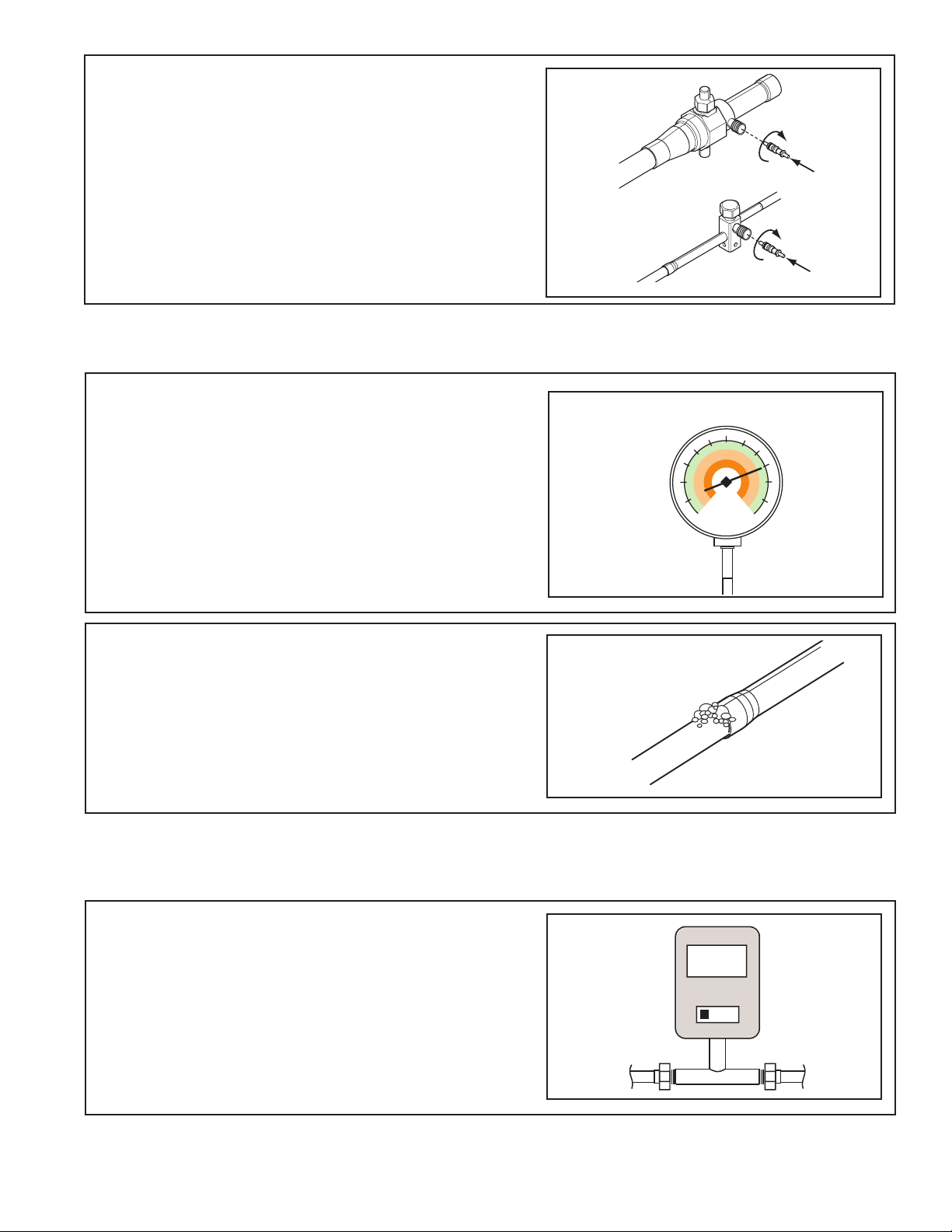
Extreme caution should be exercised when opening the
Liquid Line Service Valve. Turn counterclockwise until
the valve stem just touches the rolled edge. No torque is
required. Failure to follow this warning will result in abrupt
release of system charge and may result in personal injury
and /or property damage.
UNIT CONTAINS R-410A REFRIGERANT!
R-410A operating pressures exceed the limit of R-22. Proper ser-
vice equipment is required. Failure to use proper service tools may
result in equipment damage or personal injury.
USE ONLY R-410A REFRIGERANT AND APPROVED POE COM-
PRESSOR OIL.
LIVE ELECTRICAL COMPONENTS!
During installation, testing, servicing, and troubleshooting of
this product, it may be necessary to work with live electrical
components. Failure to follow all electrical safety precau-
tions when exposed to live electrical components could
result in death or serious injury.
The appliance is not to be used by persons (including
children) with reduced physical, sensory or mental capabili-
ties, or lack of experience and knowledge, unless they have
been given supervision or instruction.
Children should be supervised to ensure that they do
not play with the appliance.
If using existing refrigerant lines make certain that all
joints are brazed, not soldered.
Scroll compressor dome temperatures may be hot. Do
not touch the top of compressor; it may cause minor
to severe burning.
IMPORTANT — This Document is customer property and is to
remain with this unit. Please return to service information pack
upon completion of work.
These instructions do not cover all variations in systems, nor
do they provide for every possible contingency to be met in
connection with the installation. Should further information
be desired, or should particular problems arise which are not
sufficiently covered for the purchaser’s purposes, the matter
should be referred to your installing dealer or local distributor.
Table of Contents
Section 1. Safety...........................................................................................................................................................2
Section 2. Unit Location Considerations.......................................................................................................................3
Section 3. Unit Preparation...........................................................................................................................................4
Section 4. Setting the Unit.............................................................................................................................................5
Section 5. Refrigerant Line Considerations...................................................................................................................5
Section 6. Refrigerant Line Routing...............................................................................................................................6
Section 7. Refrigerant Line Brazing...............................................................................................................................7
Section 8. Refrigerant Line Leak Check........................................................................................................................9
Section 9. Evacuation....................................................................................................................................................9
Section 10. Service Valves...........................................................................................................................................10
Section 11. Electrical - Low Voltage.............................................................................................................................10
Section 12. Electrical - High Voltage.............................................................................................................................12
Section 13. Start Up......................................................................................................................................................12
Section 14. System Charge Adjustment.......................................................................................................................13
Section 15. Checkout Procedures and Troubleshooting...............................................................................................17
Section 16. Refrigeration Circuits..................................................................................................................................21
ALL phases of this installation must comply with NATIONAL,
STATE AND LOCAL CODES
Section 1. Safety