Ameristar M4MHW15-A User manual

INSTALLATION INSTRUCTIONS
FEATURING R-410A
15 SERIES Indoor High Wall for Use with Multi-Split Applications
Multi Zone Inverter System
Multi Split Indoor Unit
Heat Pump M4MHW15-A
88-M4MHW15M-1A-EN
This Installation Guide is for use only when applying the M4HW15 indoor unit with
a M4THM model multi-split outdoor unit. If installing with a single zone mini split
outdoor unit, consult the installation manual shipped with the outdoor unit

WARNING
This equipment is to be serviced by professionally trained personnel
ONLY. Under NO circumstances should an unqualified person service it.
This equipment contains refrigerant under PRESSURE and operates at
HIGH VOLTAGE. Improperly installed, adjusted or altered equipment by an
unqualified person poses safety hazards including FIRE, ELECTROCUTION,
or EXPLOSION, which could result in death or serious injury.
Warnings and Cautions
Warnings are provided to alert others of the potential hazards that could
result in severe personal injury or death, while cautions are designed
to alert others of the conditions that could result in minor or moderate
injury.
Your personal safety and the proper operation of this machine depend
upon the strict observance of these precautions.
Attention: Warnings and Cautions appear at appropriate sections
throughout this literature. Read these carefully.
WARNING: Indicates a potentially hazardous situation which, if not
avoided, could result in death or serious injury.
CAUTION: Indicates a potentially hazardous situation which, if not
avoided, could result in minor or moderate injury. It may also be used
to alert against unsafe practices.
NOTICE:Indicates a situation that could result in equipment or
property damage.
WARNING
Electrocution and Fire Hazards with Improperly Installed and Grounded
Field Wiring!
Improperly installed and grounded field wiring poses FIRE and
ELECTROCUTION hazards.To avoid these hazards, you MUST follow
requirements for field wiring installation and grounding as described in
the National Electrical Codes (NEC) and your State and/or local electrical
codes. All field wiring MUST be performed by qualified personnel.
Failure to follow these requirements could result in death or serious injury.

Warnings and Cautions
WARNING
R410-A Refrigerant under Higher Pressure than R-22!
The units described in this manual use R410-A refrigerant which operates at 50 to 70%
higher pressures than R-22. Use only R-410A approved service equipment. Refrigerant
cylinders are painted with "pink" color to indicate the type of refrigerant and may contain
a "dip" tube to allow for charging of liquid refrigerant into the system. For specific handling
concerns with R-410A, please contact your local sales office.
Failure to use R-410A approved service equipment could result in standard equipment
exploding under R-410A higher pressure which could result in death or serious injury.
NOTICE
Use appropriate oil with R410A systems. Oil type is found at the bottom of Connection Pipe
Requirements table (included in the outdoor unit installation manual). R-410A systems
utilize POE (Polyolester) or PVE(Polyvinyl Ether) oil. Both oil types absorb moisture readily,
yet, lubrication properties vary. Do not leave the sealed system open to atmosphere except
during service for a short period of time. If the sealed system is left open longer than four
hours, the compressor oil must be changed.These systems utilize strainers placed before
and after the expansion device in the outdoor unit, if debris or moisture is suspected, these
strainers must be changed. Do not break a vacuum with air. Do not leak check the sealed
system with compressed air. Unless instructed by factory service representative, external
refrigeration driers are prohibited.
USE ONLY THE FACTORY RECOMMENDED OIL TYPE!
Important!
Environmental Concerns
Scientific research has shown that certain man-made chemicals can affect the earth's naturally occurring
stratospheric ozone layer when released to the atmosphere. In particular, several of the identified chemicals that
may affect the ozone layer are refrigerants that contain chlorofluorocarbons (CFC's) and those containing hydro-
chlorofluorocarbons (HCFC's). Not all refrigerants containing these compounds have the same potential impact
to the environment.The Company advocates the responsible handling of all refrigerants, including industry
replacements for CFC's such as HCFC's and HFC's.
Responsible Refrigerant Practices
The manufacturer believes that responsible refrigerant practices are important to the environment, our
customers, and the air conditioning industry. All technicians who handle refrigerants must be certified.The
Federal Clean Air Act (Section 608) sets forth the requirements for handling, reclaiming, recovering and recycling
of certain refrigerants and the equipment that is used in these service procedures. In addition, some states or
municipalities may have additional requirements that must also be adhered to for responsible management of
refrigerants. Know the applicable laws and follow them.

Contents
Safety Precautions .................................................................................................................... 5
Pre-Installation Checklist ........................................................................................................... 6
Items Shiped with the Unit......................................................................................................... 7
Necessary Tools ........................................................................................................................ 7
Clearance Requirements........................................................................................................... 8
Installation Location................................................................................................................... 9
Installing the Indoor Unit.......................................................................................................... 10
Mounting Location ................................................................................................................... 10
Drilling the Piping Hole ............................................................................................................ 11
Refrigerant Piping at the Indoor Unit ....................................................................................... 12
Installing the Condensate Pipe................................................................................................ 14
Wiring at the Indoor Unit.......................................................................................................... 14
Binding the Pipes and Cables ................................................................................................. 16
Hanging the Indoor Unit........................................................................................................... 16
Refrigerant Piping Tips ............................................................................................................ 17
Flaring Process ....................................................................................................................... 17
Insulating the Refrigerant Piping and Connections ................................................................. 17
Wiring Diagrams ...................................................................................................................... 18
Unit Dimensions ...................................................................................................................... 19
Auxillary Operation .................................................................................................................. 21
Maintenance of the Indoor Unit ............................................................................................... 21

5
Ameristar 15 Series Multi-Split High Wall Indoor Unit
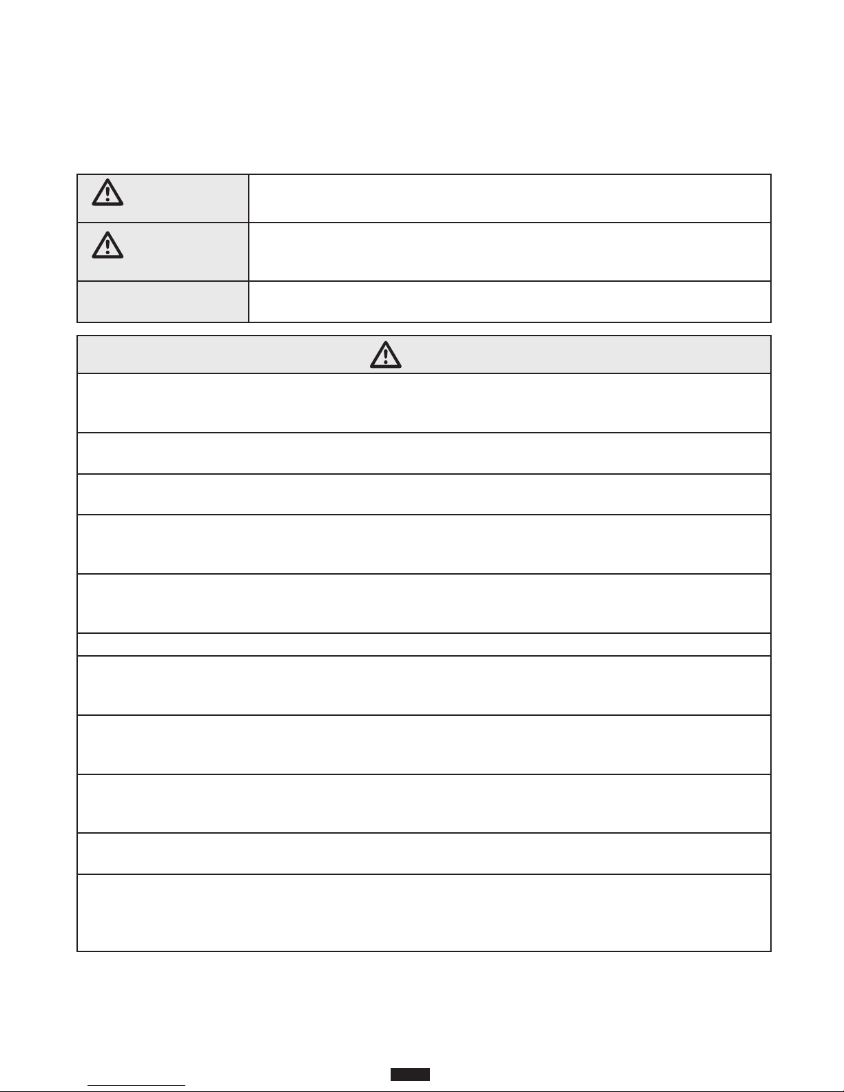
WARNING This mark indicates a potentially hazardous situation which, if not avoided,
could result in death or serious injury.
CAUTION
This mark indicates a potentially hazardous situation which, if not avoided,
could result in minor or moderate injury. It may also be used to alert against
unsafe practices.
NOTICE This mark indicates a situation which could result in equipment and/or
property damage.
Safety Precautions
Your personal safety and the proper operation of this equipment depend upon the strict observance of
these precautions.
WARNING
1. Installation should performed by a qualified HVAC professional.Industry Standard Personal
Protective Equipment (PPE) and gear for height related safety should be worn during installation.
Improper personal safety precautions and installation may cause death or serious injury.
2. Install the air conditioner according to the instructions given in this manual. Incomplete installation
work may cause water leakage, electrical shock or fire.
3. Use the supplied or specified installation parts. Use of other parts may cause the unit to come
loose, resulting in water leakage, electrical shock or fire.
4. Install the unit in a location that can support the weight of the unit. An inadequate support
structure or incomplete installation may cause injury or property damage in the event the unit falls
off of the installation location. Refer to the installation specifications for additional requirements.
5. Electrical work should be carried out in accordance with the installation manual and local, state
and National Electric Code (NEC). Insufficient capacity or incomplete electrical work may cause
electrical shock or fire.
6. Use a dedicated power circuit. Never use a power supply shared by another appliance.
7. For wiring, use a cable that is long enough to cover the entire distance without splicing. Do not
use an extension cord. Do not put other loads on the power supply; use a dedicated power circuit.
Failure to do so may cause abnormal heat, electric shock or fire.
8. Use the specified types of wires for electrical connections between the indoor and outdoor units.
Firmly clamp the interconnecting wires so their terminals receive no external stresses. Incomplete
connections or clamping may cause terminal overheating or fire.
9. After joining the interconnecting and supply wiring, shape the cables so that they do not put undue
force on the electrical covers or panels. Install covers over the wires. Incomplete cover installation
may cause terminal overheating, electrical shock, or fire.
10. If any refrigerant leaks out during the installation, ventilate the room. The refrigerant produces a
toxic gas if exposed to flames.
11. When installing or relocating the system, keep the refrigerant circuit free from substances
other than the specified refrigerant (R410-A), such as air. The presence of air or other foreign
substances in the refrigerant circuit can cause an abnormal pressure rise or rupture, which could
result in injury and damage.

6
Ameristar 15 Series Multi-Split High Wall Indoor Unit
12. If a system pump-down is performed, turn off the associated equipment and close service valves
prior to removing the refrigerant piping. Failure to do so will introduce non-condensables in the
system, causing abnormal pressure in the refrigeration cycle which could lead to injury and
damage.
13. Before system start-up, attach the refrigerant piping securely. Failure to do so will introduce non-
condensables into the system when the compressor is running, causing abnormal pressure in the
refrigeration cycle which could lead to injury and damage.
14. Establish a complete ground. Do not ground the unit to a utility pipe, arrester, or telephone ground.
An incomplete ground may cause electrical shock, or fire. A high surge current from lightning or
other sources may cause damage to the air conditioner.
15. If the power supply cable is damaged, it must be replaced by the manufacturer, its service agent
or another qualified professional in order to avoid electrical risk during and after replacement.
Pre-Installation Checklist
1. Unpack and inspect each unit.
2. Check for any damage to the unit.
3. Check the model numbers to ensure a proper match.
4. Check the unit nameplate to ensure the proper electrical requirements will be met.
5. Check the installation locations to ensure the weight of the units can be supported.
6. Check the refrigerant pipe sizes and ensure they have been or will be installed according to the
requirements in this manual.
7. Check the outdoor unit nameplate for electrical power supply and wiring requirements to ensure the
proper wiring has been installed prior to connection.
8. Check the indoor unit for coil leakage. The pressure relief valve on the gas pipe should release
pressurized nitrogen which ensures the unit has not leaked during shipping.
CAUTION
1. Do not install the unit in a place where there is danger of exposure to flammable gas leakage. If
gas leaks and builds up around the unit, it may result in fire.
2. After system installation is completed, make sure no refrigerant leakage is present.
3. This appliance is not intended for use by persons with a lack of experience and knowledge, unless
they have been given adequate supervision or instruction concerning use of the appliance by a
person responsible for their safety.
4. Children should be supervised to ensure that they do not play with the appliance.
NOTICE
1. Establish drain piping according to the instructions in this manual. Inadequate piping may cause
flooding.
2. Tighten the flare nut according to the specified method. If the flare nut is tightened too hard, the
flare nut may crack and cause refrigerant leakage.

7
Ameristar 15 Series Multi-Split High Wall Indoor Unit
Items Shipped with the Ameristar 15 Series Multi-Split High Wall Indoor Unit
After unpacking the unit(s), please refrain from disposing of the packaging materials until items
listed below are located. If any of these are missing, please contact the point of sale to obtain
these items.
Indoor Unit
1. Wireless handheld remote control
2. Refrigeration pipe insulation (short piece)
3. Mounting Plate
4. Installation instructions (may be included in outdoor unit)
5. Batteries for the remote control*
6. Flare nuts for connecting refrigerant pipes*
7. Mounting fasteners*
*typically packaged in cellophane bubble
Necessary tools
1. Drill
2. Hole Saw
3. Phillips(TM) screwdriver
5. Vacuum pump capable of pulling to 350 microns
6. Manifold gauge set designed for this type of equipment
7. Manifold gauge hoses with 5/16" connections or 1/4" to 5/16" adapters.
8. Tubing benders
9. R-410A Flaring tool
10. Adjustable wrench
11. Nitrogen regulator
12. Nitrogen flow meter
13. Tube cutter

8
Ameristar 15 Series Multi-Split High Wall Indoor Unit
valve cover
Space to the wall
Space to the ceiling
Space to the wall
Space to the wall
Air outlet side
Space to the floor
or more
or more
6 in. or more 6 in. or more
12 in. or more
20 in. or more
20 in. or more
12 in. or more
or more
.n
i
97
or more
Space to the obstruction
Air outlet side
Space to the wall
Air inlet side
The dimensions of the space necessary for correct
installation of the appliance including the minimum
permissible distances to adjacent structures
6 in.
66
in.
118 in.
Clearance Requirements
NOTE:
The maximum recommended height from the floor to the bottom of the indoor unit is 11.5 ft. (3.5 m).
Refrigeration piping and
high voltage wiring, including
communication and ground
wiring to the multi-split
outdoor unit.
Note: Refrigeration piping size, length and additional charge is discussed in the Installer's
Guide associated with the outdoor unit.

9
Ameristar 15 Series Multi-Split High Wall Indoor Unit
WARNING
Adequate Support Required!
The wall structure must be adequate to support the weight of the unit. Failure to ensure
adequate structural support could result in death, serious injury, and equipment or
property damage.
Installation Location
Indoor Unit
1. Avoid locating the indoor unit where the return and/or supply air may be obstructed.
2. Select a location where equipment condensate can be appropriately drained.
3. Keep the indoor unit away from heat sources, vapor, and flammable gas.
4. Select a location that meets or exceeds the clearance specifications in this manual.
5. Allow space for routine maintenance, such as changing filters or servicing the equipment.
6. Install in a location sufficiently away from other electronic appliances that could cause interference,
such as television, audio devices, etc.
NOTICE
Installing the unit in one of the following locations could result in unit malfunction:
1. Places where oil (machine oil) is used.
2. Seaside places with high levels of salt in the air.
3. Places with high levels of sulphur gas such as areas with hot springs.
4. Places where high-frequency waves are generated by radio equipment, welders and medical
equipment.
5. Other unusual places where unit operation may be altered.
6. Places where minimum clearances cannot be met.

10
Ameristar 15 Series Multi-Split High Wall Indoor Unit
Installing the Indoor Unit
WARNING
Hazardous Service Procedures!
The maintenance and troubleshooting procedures recommended in this section of the
manual could result in exposure to electrical, mechanical or other potential safety
hazards. Always refer to the safety warnings provided throughout this manual
concerning these procedures. Disconnect all electrical power including remote
disconnect and discharge all energy storing devices such as capacitors before
servicing. Follow proper lockout/tag out procedures to ensure the power can not be
inadvertently energized. When necessary to work with live electrical components, have
a qualified licensed electrician or other individual who has been trained in handling live
electrical components perform these tasks. Failure to follow all of the recommended
safety warnings provided, could result in death or serious injury.
Mounting Location
1. Confirm the mounting location with the customer. Keep in mind the guidelines for a
safe installation location on page 8-9.
2. Place the wall-mounting frame on the wall and check that it is level. Mark the screw
holes to be drilled, ensuring they are in a place with adequate support.
a) It is equally important to assure the mounting surface (i.e. wall) is flat. Use a
straight edge to assure the section of the mounting surface, in which the unit will
be secured, is neither concave or convex.
b) For corrugated walls, indoor unit installation is recommended on a solid
backing affixed to the wall.
3. Drill the holes on the wall according to the selected marks. If the mounting plate
cannot be directly affixed to wall studs or other solid backing, wall anchors shall be
used to secure mounting plate.
4. Attach the wall-mounting frame with the supplied tapping screws and check to make
sure it is firmly attached. If any of the screws or anchors are loose, select another
point on the frame to re-drill and attach securely.
5. Be sure that the wall-mounting frame has been secured firmly enough to withstand
the weight of the unit. The weight should be evenly distributed to the fasteners.
6. Prior to leaving the job site, seal any and all openings in the wall caused by the
installation process.

11
Ameristar 15 Series Multi-Split High Wall Indoor Unit
Left
Wall
Φ2 1/4 inch (57mm)
Right
Mark in the middle of it Level
Rear piping hole
Wall
Space
to the
wall
min.
6 inch
Space
to the
wall
min
6 inch
Φ2 1/4 inch (57mm)
Rear piping hole
12K:09K:
Left
Wall
Φ2 1/4 inch (57mm)
Right
Mark in the middle of it Level
Rear piping hole
Wall
Space
to the
wall
min.
6 inch
Space
to the
wall
min.
6 inch
Φ2 1/4 inch (57mm)
Rear piping hole
Left
Wall
Φ2 3/4 inch (70mm)
Right
Mark in the middle of it Level
Rear piping hole
Wall
Space
to the
wall
min.
6 inch
Space
to the
wall
min.
6 inch
Φ2 3/4 inch (70mm)
Rear piping hole
24K:18K:
Left
Wall
Φ2 1/4 inch (57mm)
Right
Mark in the middle of it Level
Rear piping hole
Wall
Space
to the
wall
min.
6 inches
Space
to the
wall
min.
6 inches
Φ2 1/4 inch (57mm)
Rear piping hole
1. When the position of the drain piping has been selected, cut out the corresponding knock-out
from the unit housing.
2. Select the position of the piping hole to be drilled according to the direction of the drain pipe
position selected for the application. The position of the piping hole should be slightly lower
than the wall mounted frame.
3. Drill a hole with the diameter of 2 3/16 inch or 2 3/4 inch (24K unit) for the selected outlet pipe
position. In order to drain smoothly, slant the piping hole on the wall slightly downward to the
outdoor side with a gradient of 5-10°. (As shown below)
4. Insert a sleeve into the hole to prevent the connection piping and wiring from being damaged
when passing through the hole.
Drilling the Piping Hole
The piping can be connected in the direction of right, rear right, left or rear left.
Left
Rear left
Right
Rear right
Cut off
the hole
Left Right
Indoor
5-10
outdoor
Φ2 1/4 (57)
Φ2 3/4 (70)
inch(mm)

12
Ameristar 15 Series Multi-Split High Wall Indoor Unit
Refrigerant Piping at the Indoor Unit
Note: Until the outdoor unit is set and ready to connect refrigeration pipes, do not remove the caps
from the indoor unit.
NOTICE
1. Connect each pipe to its port on the indoor unit correctly. If the centering is improper, the
flare nut cannot be tightened smoothly. If the flare nut is forced to turn, the threads will be
damaged. Refer to the flaring process guidelines in this manual for additional information.
2. Do not remove the tube caps nut until the connection pipe is made ready to prevent dust and
impurities from entering the system.
NOTICE
If a wall sleeve is not used, unnecessary damage to the piping and wiring could occur. This
typically results in current loss, improper grounding, and pipe leaks, Ensure no undue forces are
on the piping and wiring through wall(s) and adequate draining still occurs.
1. When connecting refrigerant pipe to the unit or removing it from the unit, please use both a
back-up wrench and the torque wrench. See illustration on page 16.
2. When connecting, place the equipment specified oil type on the backside of the copper
tube flare prior to tightening. Do not place oil on the flare face, as this will promote system
contamination, tighten it by hand and then tighten it with the spanner or adjustable wrench.
3. Refer to the torque reference table below before tightening to determine the appropriate torque
(over-tightening will damage the nut and lead to leakage).
4. Use dry Nitrogen to pressurize the piping circuit with 150 PSIG and allow it to hold while
performing other installation processes. It is recommended to apply a soap bubble solution and
observe the connection.
5. Evacuate each individual refrigeration circuit to 350 microns or below, and close off the valve
to the vacuum pump. If the pressure rises above 500 microns within one minute, but not above
1500 microns within 5 minutes, moisture is present. If the pressure continues to rise above
1500 microns, a leak exists in the circuit being tested.
a) If moisture is present, use triple evacuation process to eliminate the moisture.
b) If a leak is present, leak check all joints and piping.
Evacuation is not completed until the micron gauge does not rise above 500 microns within
one minute after achieving 350 micron pressure vacuum.

In. (mm) Tightening Torque
1/4 (6.35) 11.25-14.75 (ft-lbf) / 15 ~ 20 N•m
3/8 (9.52) 22.25-29.50 (ft-lbf) / 30 ~ 40 N•m
1/2 (12.7) 33.25-40.50 (ft-lbf) / 45 ~ 55 N•m
5/8 (15.9) 44.25-47.75 (ft-lbf) / 60 ~ 65 N•m
13
Ameristar 15 Series Multi-Split High Wall Indoor Unit
Back-up Wrench
6. After evacuation is complete, additional charge can be added.
a) If no additional charge is required, break the vacuum with refrigerant, then remove the
gauge connectors.
b) slightly open the liquid valve at the outdoor unit, allow system to equalize, then fully
open the liquid valve and then open the vapor service valve.
7. After leak checking is complete, apply thermal insulation around the flare connections and
all exposed refrigeration pipes Refer to the guidelines for insulating refrigerant piping and
connections in this manual for additional information.
a) Seal the insulation
b) Inspect the insulation to assure no breakages are present.

14
Ameristar 15 Series Multi-Split High Wall Indoor Unit
Installing the Condensate Pipe
NOTICE
Do not sharply twist or curve the condensate drain pipe. Ensure pipe ends are not submerged in
water. Drain pipe must provide adequate flow and slope downward to the outlet. Failure to do so
may result in leakage and overflow of the drain pan.
Outlet
pipe
Drain hose
Drain hose
Tape
Outlet pipe
Drain hose
Insulating pip
e
1. Connect the drain hose to the outlet pipe of the indoor unit (shown in Fig. A below).
2. Bind the joint with tape (shown in Fig. B below).
3. Wrap the pipe with insulating tape to prevent condensation (shown in Fig. C below).
Note: The drain pipe must be routed lower and sloped downward away from the indoor unit.
Fig. A Fig. B Fig. C
Wiring at the Indoor Unit
wiring cover
screw
panel
power connection
wire
cable-cross
hole
Fig. D Fig. E
WARNING
Disconnect all electrical power and discharge all energy storing devices such as
capacitors to the outdoor unit(s) prior to wiring the indoor unit(s) to avoid risk of death,
injury, or damage to equipment.
1. Open the front panel of the indoor unit, remove the screw on the wiring cover and
remove the cover (shown in Fig. D below).
2. Thread the power connection wire through the cable-cross hole at the back of the
indoor unit and pull it through to the front side (shown in Fig. E below).

15
Ameristar 15 Series Multi-Split High Wall Indoor Unit
Outdoor unit connection
09,12, 18, 24K models:
3
2
N(1)
green
green)
red
black
(yellow-
(brown)
white
(blue)
NOTE: The wiring diagrams in this guide are included as a reference. The manufacturer
has a policy of continuous product and product data improvement and reserves the
right to change design and specifications without notice. Always check the unit
nameplate and wiring diagram for the actual unit requirements.
3. Remove the wire clip and connect the power connection wire to the wiring terminal according to
the correct color coding. It is recommended to use 4 wire colors (for example: Black, Blue, Red,
Green) Connect Black to 1, Blue to 2, Red to 3 and Green to Ground. All wiring shall use ring or
spade type crimped or soldered connectors (as shown in the outdoor unit installation section or
manual). Ensure electrical connections are tight and strain reliefs are in place. Regardless of wire
color used, The wire terminals labeled 1, 2, 3 and ground must be landed on the corresponding
terminal in the outdoor unit.
4. Put the wiring cover back on the unit and tighten the fastener.
5. Close the front panel.
6. The primary disconnect for both the indoor and outdoor unit shall be wired to disconnect the
branch circuit feeding the outdoor unit. The Indoor unit obtains high voltage and communication
from the outdoor unit. If the AHJ (authority having jurisdiction) requires a branch circuit disconnect
before the indoor unit, then break all three legs between the outdoor unit and indoor unit using a
switch with current ratings suitable for use with these types of systems.
7. The system must be disconnected at the outdoor unit before performing service or maintenance to
avoid risk of electric shock or damage to equipment.
8. Terminal 2 carries communication signals and should not be cut or spliced. Do not use splices in
any wire between the indoor and outdoor unit.
a) If an external drain pump with a float switch is utilized, power the drain pump from
terminals 1 and 3; the float switch should be wired to break leg 3.
b) Do not break leg 1 or leg 2 with a float switch.
9. The ground wire must connect directly from the outdoor unit to the indoor unit. To avoid
communication errors, do not connect the ground wire to the terminal block from any other
location.

16
Ameristar 15 Series Multi-Split High Wall Indoor Unit
Binding the Pipes and Cables
Note: The refrigeration pipes shall be insulated separately to prevent heat transfer between the
two pipes.
1. At the beginning of the indoor connections, bind the insulated refrigerant pipes, power cable,
and drain hose by evenly wrapping them with an appropriate pipe tape.
2. When the drain hose needs to be separated from the binding towards the discharge point,
separate the power cable and drain hose from this binding.
3. Wrap and secure the drain hose connection at its end.
4. Evenly wrap the separately insulated liquid and gas pipes until they are close to the outdoor
connection.
5. Near the outdoor unit connection, separately wrap these pipes.
indoor unit gas
pipe
indoor and
outdoor power cord
liquid pipe
drain hose
band
drain hose
band
connection pipe
indoor power cord
Hanging the Indoor Unit
Note: It is recommended the indoor unit be mounted on a non-porous flat surface. Doing so will
reduce unfiltered air from entering the unit as well as reduce sweating behind the unit. Ensure the
insulation sections surrounding the refrigeration and condensate pipes are sealed and without
cracks or openings.
1. Insert the bound pipes and wires into the wall sleeve and pass through to the outside.
2. Hang the indoor unit on the wall-mounting frame.
3. Seal any and all openings and gaps with sealant.
4. Secure the wall pipe bundle with saddles.
5. Ensure the indoor unit is securely and tightly installed to the wall.
6. Do not bend the drain hose excessively to prevent blockage.
sleeve
upper hook
lower hook of
wall-mounting frame

For refrigeration pipe sizing, installation, and charging, please reference the outdoor unit
installation section or separate manual if not included.
Refrigerant Piping Tips
Flaring Process
1. Hold the pipe downward to prevent cuttings from entering the pipe.
2. Using an appropriate tube cutter and deburring tool, cut and deburr the refrigerant pipe.
3. Remove the flare nuts at the stop valve of the outdoor unit and inside the accessory bag of
the indoor unit, put them onto the refrigerant pipe as shown below then flare the refrigerant
pipe with a flaring tool.
4. When flaring copper tubing, only use flaring tools that utilize an orbiting mandrel and
clutched handle. These are typically referenced as R410A flaring tools. By using this type of
flaring tool, the copper tubing is rolled while being pressed, thereby reducing the probability
of copper flare cracking.
5. Check if the flare part is spread evenly and there are no cracks.
Insulating the Refrigerant Piping and Connections
1. The refrigerant pipes should be insulated and wrapped with appropriate insulating
material and wrapping tape. This will prevent condensation, water leakage and
damage to the insulating material.
2. The connections at the indoor unit should be wrapped with insulating material. No
gap is allowed on the joint of the indoor unit, as shown below.
17
Ameristar 15 Series Multi-Split High Wall Indoor Unit

Wiring Diagrams
Indoor Unit
Color Key
Symbol Symbol Color Symbol Symbol Color Symbol Name
WH White GN Green CAP Jumper cap
YE Yellow BN Brown COMP Compressor
RD Red BU Blue Grounding wire
YE/GN Yellow/Green BK Black / /
VT Violet OG Orange / /
N(1)
2
3
Note: A "Jumper Cap" may be used to determine fan speed and the swing angle of horizontal louver
for this model. The unit will not operate without the correct jumper cap. If "Jumper Caps" are installed
on the original electrical board, they must be removed and installed on a replacement electrical
board.
18
Ameristar 15 Series Multi-Split High Wall Indoor Unit
NOTE: The wiring diagrams in this guide are included as a reference. The manufacturer
has a policy of continuous product and product data improvement and reserves the
right to change design and specifications without notice. Always check the unit
nameplate and wiring diagram for the actual unit requirements.

Indoor Unit Dimensions
W
D
H
3 1/2
6
2 1/8 2 1/8
6 5/8 18 3/16 6 5/16
Φ2 3/16
Φ2 3/16 Φ2 3/16
Φ2 3/16
4 11/16 21 5/16 7 1/4
3 5/16
5
1 3/8 1 3/8
MODEL W H D
09K 31 1/8 10 5/8 7 7/8
12K 33 1/4 11 3/8 8 1/4
09K
12K
Unit:inch
9K-12K Indoor Units
The dimensions in these drawings
are rounded according to standard
measurement.
19
Ameristar 15 Series Multi-Split High Wall Indoor Unit

18K-24K Indoor Units
WD
H
24 77 3/16
5 1/2
7 1/2
1 1/2
Φ2 3/16 Φ2 3/16
3 1/8
6
1 11/16
8 1/8 27 7 5/16
Φ2 3/4 Φ2 3/4
Unit:inch
18K
24K
Models W H D
18K 38 1/4 11 13/16 8 7/8
24K 42 1/2 12 13/16 9 11/16
Indoor Unit Dimensions, continued
The dimensions in these drawings
are rounded according to standard
measurement.
20
Ameristar 15 Series Multi-Split High Wall Indoor Unit
Other manuals for M4MHW15-A
1
Table of contents
Other Ameristar Air Conditioner manuals
Popular Air Conditioner manuals by other brands

Toshiba
Toshiba MMU-UP0031YHP-E installation manual

Hitachi
Hitachi RAS-PH18PHLAE Service manual

Olimpia splendid
Olimpia splendid MAESTR SMART Instructions for installation, use and maintenance

LG
LG L1010ER Specifications

Panasonic
Panasonic CS-ME7NKE Technical & service manual

Panasonic
Panasonic S-18MK2U6 operating instructions

LG
LG ARNU24GS5A2 owner's manual

Wood’s
Wood’s CORTINA Silent 9K Eco operating instructions

LG
LG G12NHC owner's manual

Trane Technologies
Trane Technologies Precedent TZJ150A Installation, operation and maintenance

Carrier
Carrier 48TFD008-014 Installation and service instructions

TECHWOOD
TECHWOOD TCL-7001 instruction manual