manuals.online logo
Brands
  1. Home
  2. •
  3. Brands
  4. •
  5. Ametek
  6. •
  7. Cables And Connectors
  8. •
  9. Ametek Land Spot User manual

Ametek Land Spot User manual

Popular Cables And Connectors manuals by other brands

StarTech.com ST124HD20 quick start guide

StarTech.com

StarTech.com ST124HD20 quick start guide

Philips SWV4543S/10 Features

Philips

Philips SWV4543S/10 Features

Larson Electronics 10-50C instruction manual

Larson Electronics

Larson Electronics 10-50C instruction manual

Grip MEK-PM Assembly and operating manual

Grip

Grip MEK-PM Assembly and operating manual

Ultra Products Travel Pack #3 ULT31436 Specifications

Ultra Products

Ultra Products Travel Pack #3 ULT31436 Specifications

Surpass QCH-F Operation manual

Surpass

Surpass QCH-F Operation manual

Philips SWA6310 Specifications

Philips

Philips SWA6310 Specifications

StarTech.com CRJ4550PK quick start guide

StarTech.com

StarTech.com CRJ4550PK quick start guide

Nohau EMUL-IP2K-PC user guide

Nohau

Nohau EMUL-IP2K-PC user guide

Foxun SX-SP144E-HD4K2K operating instructions

Foxun

Foxun SX-SP144E-HD4K2K operating instructions

Philips SWA3305W Specifications

Philips

Philips SWA3305W Specifications

opticis Stretch DVIM1-1P0x user manual

opticis

opticis Stretch DVIM1-1P0x user manual

Volkswagen VAS 6558A operating manual

Volkswagen

Volkswagen VAS 6558A operating manual

NEXIBO N-13 user manual

NEXIBO

NEXIBO N-13 user manual

CYP PU-1H3HBTL Operation manual

CYP

CYP PU-1H3HBTL Operation manual

Allen-Bradley 1784-u2dhp installation instructions

Allen-Bradley

Allen-Bradley 1784-u2dhp installation instructions

Global Caché Flex Link Blaster quick start

Global Caché

Global Caché Flex Link Blaster quick start

Hauppauge USB-Live2 Quick installation guide

Hauppauge

Hauppauge USB-Live2 Quick installation guide

manuals.online logo
manuals.online logoBrands
  • About & Mission
  • Contact us
  • Privacy Policy
  • Terms and Conditions

Copyright 2025 Manuals.Online. All Rights Reserved.

Installation Dimensions
Land Instruments International
Droneld, S18 1DJ
England
Telephone: +44 (0) 1246 417691
Facsimile:
Email:
Internet:
+44 (0) 1246 410585
[email protected]
www.ametek-land.com
AMETEK Land, Inc.
150 Freeport Road
Pittsburgh PA 15238 U.S.A.
Telephone: (412) 826-4444
Facsimile: (412) 826-4460
Email: [email protected]
Internet: www.ametek-land.com
SPOT
INSTALLATION GUIDE
PUBLICATION NO809136
LANGUAGE: ENGLISH
ANALOGUE CONNECTION PCB
i
QUALITY CUSTOMER SOLUTIONS
809136, Issue 6, 05 June 2017
Installation Instructions
The Analogue Connection PCB provides electrical terminal
connections for an Analogue Cable connected to a Land SPOT
Thermometer.
There are three lengths of analogue output cable available as
standard:
• 5 m / 16 ft Part Nº 807950
• 20 m / 66 ft Part Nº 807951
• 100 m / 328 ft Part Nº 807952
You can use the connection PCB to access the required analogue
outputs from the SPOT Thermometer.
The Analogue Connection PCB is designed to be tted to a
standard 35mm DIN rail.
Each terminal must be tightened to a torque setting of 0.45 to
0.50 Nm
1) Choose a mounting location for the Analogue Connection
PCB so that the analogue cable can be routed securely and
safely from the thermometer to the PCB.
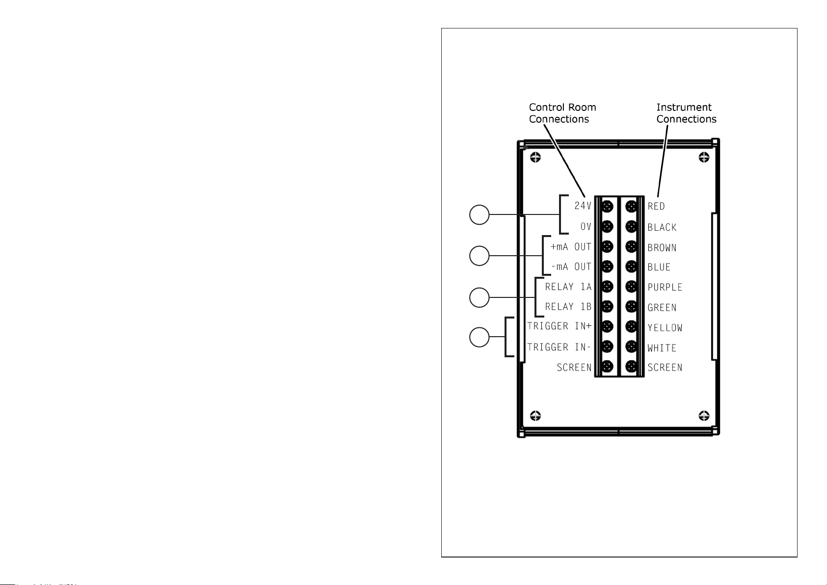
2) Refer to Electrical Connections (Fig. 1). Connect the free
ends of the Analogue Cable to the Instrument Connections
terminals on the PCB. Match the wire colour to the
appropriate terminal.
3) You can now use the Control Room Connections terminals
to connect to the required analogue outputs from the SPOT
Thermometer. Refer to Fig. 1 and the terminal labels on
the PCB to identify which analogue outputs are available.
Key to Control Room Connections
1 DC Power 24V (18 to 30V).
2 Current output, congurable as 0 to 20mA or 4 to 20mA
with associated temperature range.
3 Relay used for instrument CMD Out, congurable as
Normally Open (NO) or Normally Closed (NC). This output
can be used as a switch in circuits up to 50V.
4 24V DC input used for instrument CMD In, congurable as
NO/NC.
Each of the above outputs can be congured on the SPOT
instrument back panel, on the Webserver, or in the Viewer software.
Fig. 1
Electrical Connections
1
2
3
4
Note:
Torque settings for connection terminals:
Minimum: 0.45 Nm
Maximum: 0.50 Nm