Surpass QCH-F User manual

QCH-F(E)Ver.1.1
Fluoropolymers
Quick Connector
QCH-F
Plug/Socket
Operation Manual
Before you use, carefully read this manual for an appropriate
handling of this product. And, keep this manual close at hand
for quick reference if necessary.
Surpass Industry Co., Ltd.

2
CONTENTS
Before You Use ······································· 3
Important Safety Instructions··························· 4〜6
1.Description ······································· 7
2.Application········································ 7
3.Specification ······································ 8
4.Destinations of Parts······························· 9
5.Mounting ········································· 10
5-1Unpacking···································· 10
5-2Where to Mount ······························· 10
5-3Attaching Flange ······························ 10〜11
6.Mounting Procedures ······························ 12
6-1Connecting Procedures ························ 12〜13
6-2Fluid Transport ································ 14
6-3Disconnecting Procedures ······················ 14
7.Inspection and Maintenance ························ 15
7-1Periodic Inspection ···························· 15
7-1-1Replacing Valve O-Rings ··················· 15〜17
7-1-2Replacing Plug-Seal O-Rings ··············· 17〜18
7-2Daily Inspections ······························ 18
8.Troubleshooting ··································· 19
9.Product Warranty·································· 20

3
Before You Use
< Description of Operation Manual and Warning Labels >
●The information described in this manual is subject to change without
prior notice, due to improvements of product in performance and/or
functionality.
●The simplified QCH-ANSI-F Quick Connector Operation Manual
(printed on one sheet of A4-sized paper) that is packed in each
connector package must be stored close to the
connector-mounted place for quick reference as it needed.
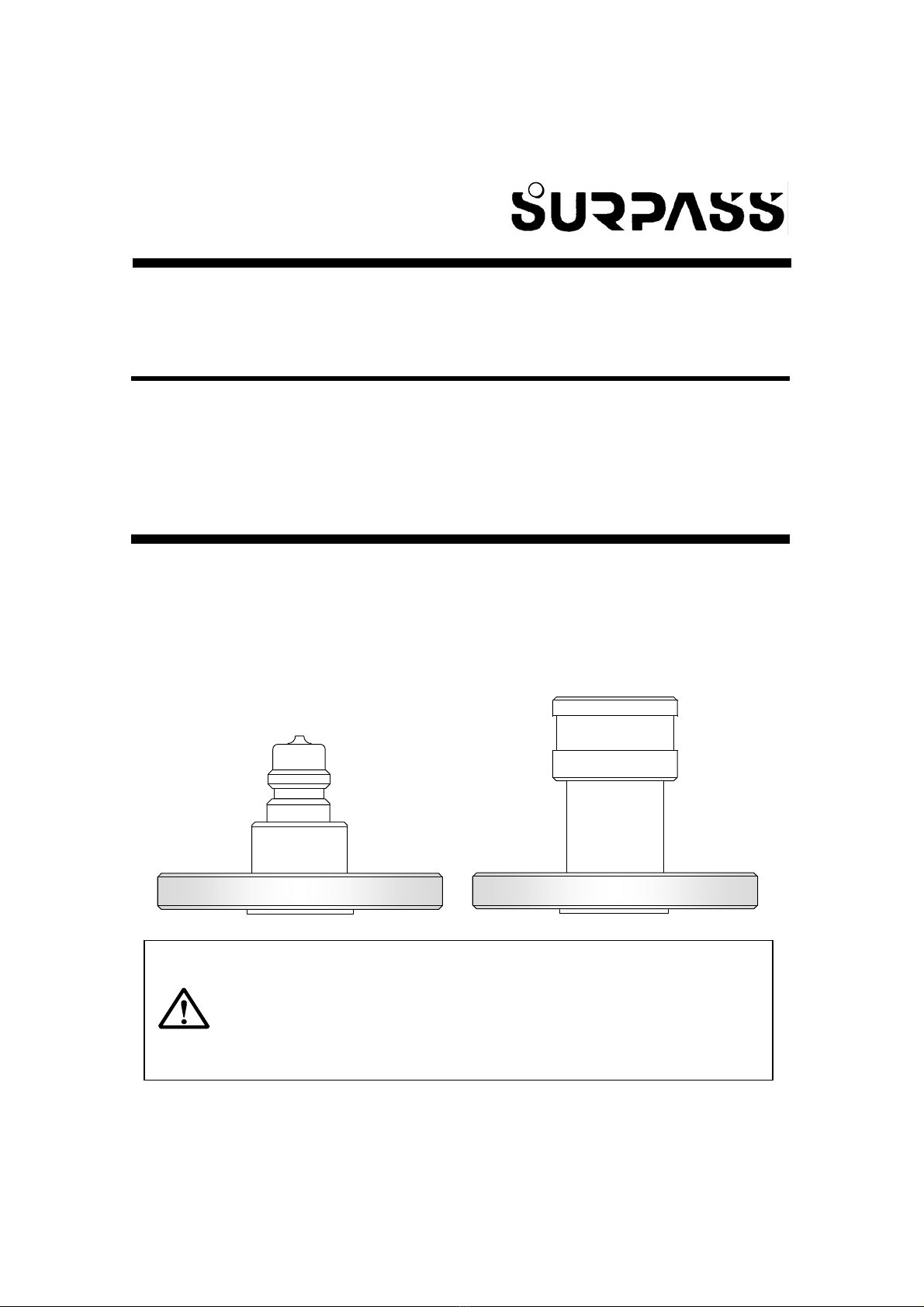
●The WARNING label instructing handling of socket must be
labeled on an easily visible spot close to the socket-mounted
place.
●No parts of Operation Manual may be reproduced or utilized in any
form or by any means.
●Please call Surpass Industry if you lose Operation Manual.
●Every effort was made to ensure that all information included in
Operation Manual were complete and accurate at the time of printing.
However, if you have any point of doubt, errors, and omissions, please
contact Surpass Industry.
●Before use of this product, carefully read this manual so that you can be
familiar with its information.
●Keep this operation manual close at hand for quick reference if
necessary.
●For safety operation, obey the primary usage of product or the mounting
procedure specified in this manual.
●Comply with the statements of warnings described in this manual.
The above instructions are mandatory. Neglect of instructions may result in
personal injury or accidents.
WARNING
<Call to:>
Surpass Industry Co., Ltd.
2203 Shimooshi, Gyoda-shi, Saitama 361-0037 Japan
Tel.: +81 48 554 9760Fax.: +81 48 554 9906
URL:http://www.surpassindustry.co.jp
C2002 Surpass Industry Co.,Ltd. All rights reserved.

4
Important Safety Instructions
Description of Marks Used in This Manual
This manual provides the marks including DANGER, WARNING, and
CAUTION, used to avoid personal injury or property damage accidents.
The meanings of marks are described as follows.
Before reading this manual, completely understand the meanings of these
marks and obey the instructions described in this manual.
In particular, completely understand and obey the statement of
DANGER mark.
DANGER
Indicates an imminently hazardous situation that, if not
avoided, could result in user death or serious
injury.
WARNING
Indicates a potentially hazardous situation that, if not
avoided, could result in user death or serious injury.
CAUTION
Indicates a potentially hazardous situation that, if not
avoided, could result in user injury or property damage
accidents.
Indicates the notes including key instructions to
correctly operate the product.

5
DANGER and WARNING Statements
Before use of this product, carefully read the statements of DANGER and
WARNING marks and comply with them.
○General Instructions on Mounting
DANGERThis is Mandatory Rule.
●Whenever using this product for hazardous chemical fluids or
solvents, wear anti-chemical protective gear (protective gloves,
protective mask, and protective clothing) that completely protects
your body. Exposure of chemical fluids may result in personal
injury.
WARNING
●Use the flange in the specified usage and connecting procedures.
Connection of flanges in the wrong usage or procedure may result in
personal injury due to leakage of chemical fluids.
○Instructions on Handling
WARNING
●Do not damage the connecting part (wound with seal-tape) of plug and
socket. Damage of product may result in personal injury due to
leakage of chemical fluids.
●Do not contact the connector to any rigid materials because it is made
of resin materials. Damage of product caused by contact may result in
personal injury due to leakage of chemical fluids.

6
○Instructions on Mounting
DANGERThis is Mandatory Rule.
●Connect or disconnect the connector to the tube whose internal
pressure is not pressurized. A pressurized condition may result in
personal injury due to exposure of chemical fluids.
●Whenever connecting or disconnecting the connector, wear
anti-chemical protective gear (protective gloves, protective mask,
and protective clothing) that completely protects your body. A
touch of chemical fluids may result in personal injury.
●Connect or disconnect the connector in a cleanly place with no
dust. Lower tackiness caused by dust may result in personal injury
due to leakage of chemical fluids.
●Do not apply the connector to rotary joint or other rotary
application. Lower tackiness caused by the wrong application may
result in personal injury due to leakage of chemical fluids.
○Instructions on Inspection and Maintenance
WARNING
●Replace O-Ring in the specified replacing procedures. A replacement
work in the wrong procedures may result in personal injury due to
leakage of chemical fluids or unexpected accidents.

7
1. Description
Fluoropolymers Quick Connector Series are the "one-touch" (instant lock)
typed connectors for high-purity chemicals used in semi-conductor
manufacturing process. These connectors have proven their reliability and
convenience over many years. Also, repeated efforts to improve
chemical-resistance, leak-resistance, and particle reduction for higher
quality allow our connectors to be applied to various type chemicals.
2. Application
●Containers for high-purity semi-conductor chemicals
●Semi-conductor manufacturing equipment
●Biochemistry, physics and chemistry equipment
●Pure water equipment
●Medical equipment
●Environmental equipment
・Do not use the connector for slurry liquids or liquids containing
foreign substances.

8
3. Specification
■Operating Pressure:Max. 450 kPa (65.2 psi)
■Operating Temperature Range :5°C 〜70°C
(41°F 〜158°F)
■Materials of Parts in Contact with Liquid:PCTFE, PTFE, PFA
■Model Type:Refer to the figure as
below.
QCH−□□−□P−□F
JIS Flange
Plug Indication
P:Plug
Connector Size
6:Compatible with QCH−□□−6□
25A:Compatible with QCH−□□−25A□
40A:Compatible with QCH−□□−40A□
O-Ring on a Valve
L:O-Ring-less
K: Kalrez®O-Ring
Valve Type
N:Non-Valve
W: Double Valve
QCH−□F□−□S−□F
JIS Flange
Socket Indication
S : Socket
Connector Size
6:Compatible with QCH−□□−6□
25A:Compatible with QCH−□□−25A□
40A:Compatible with QCH−□□−40A□
O-Ring on a Valve
L:O-Ring-less
K: Kalrez®O-Ring
O-Ring Type:FEP JAKET O-Ring
Valve Type
N:Non-Valve
W: Double Valve
Plug
Socket
−F 6P:10K20A
25AP:10K25A
40AP:10K40A
−15AF:10K15AF
−25AF:10K25AF
−40AF:10K40AF
−50AF:10K50AF
−F 6S:10K20A
25AS:10K25A
40AS:10K40A
−15AF:10K15AF
−25AF:10K25AF
−40AF:10K40AF
−50AF:10K50AF

9
4. Destinations of Parts
Sectional View of Plug
Sectional View of Socket
Valve
Plu
g
O-Ring (not used for
O-Ring-less type)
Spring
Stopper
Flange
Stop ring
Spring
Valve
Socke
t
Flange
O-Ring (not used for
O-Ring-less type
Spring
Stopper
Plug-Seal O-Ring
Ball
Sleeve

10
5. Mounting
DANGERThis is Mandatory Rule.
●Whenever using this product for hazardous chemical fluids or
solvents, wear anti-chemical protective gear (protective gloves,
protective mask, and protective clothing) that completely protects
your body. Exposure of chemical fluids may result in personal
injury.
5-1 Unpacking
Carefully unpack the package not to damage the plug and
socket.
5-2 Where to Mount
■Mount the connector in the place where the bending or
tensile stress can not be produced.
■Mount the connector in the place where excessive vibration
or shock can not be produced.
5-3 Attaching Flange
WARNING
●Use the flange in the specified usage and the attaching procedures.
Attach of flanges in the wrong usage or procedures may result in
personal injury due to leakage of chemical fluids.
①Select the gasket that is made of any materials suitable
for your usage.
②Remove any foreign particle or dirt from the surface of
attaching part.
③Insert the gasket into the attaching part and tighten the
nut.
・When tightening the nut, screw the bolts in crosswise order so
that the flange can be evenly tightened.
・For tightening torque of nut, refer to the table "Tightening Torque
of Flange Nut (Reference Value)".

11
④Refer to the table as below and tighten the flange.
―Tightening Torque of Flange Nut (Reference Value)―
Flange SizeNut Tightening Torque Reference Value
20A
25A
40A
8.0±2.0N・m
14.0±4.0N・m
29.0±6.0N・m
⑤Make sure that there is no leakage from the attaching part
of flange.

12
6. Mounting Procedures
DANGERThis is Mandatory Rule.
●Connect or disconnect the connector to the tube whose internal
pressure is not pressurized. A pressurized condition may result in
personal injury due to exposure of chemical fluids.
●Whenever connecting or disconnecting the connector, wear
anti-chemical protective gear (protective gloves, protective mask,
and protective clothing) that completely protects your body. A
touch of chemical fluids may result in personal injury.
●Connect or disconnect the connector in a cleanly place with no
dust. Lower tackiness caused by dust may result in personal
injury due to leakage of chemical fluids.
●Do not apply the connector to rotary joint or other rotary
application. Lower tackiness caused by the wrong application
may result in personal injury due to leakage of chemical fluids.
6-1 Connecting Procedures
①Before connecting the connector, make sure that the
pressure in tube is not pressurized.
DANGERThis is Mandatory Rule.
●A pressurized condition may result in personal injury due to
exposure of chemical fluids. Connect or disconnect the
connector to the tube whose internal pressure is not pressurized.
②Pull the socket sleeve by hand.(See Fig. 1 and photo.)
・Whenever connecting the socket, pull the sleeve by hand.
Pulling sleeve allows socket connection.
Fig. 1
Plug Pull the sleeve

13
③Insert the socket into the plug by pulling the socket sleeve
until the head of socket reaches the plug.
(See Fig. 2 and photo.)
Fig. 2
Insert the socket
④Return the socket sleeve to its origin position.
(See Fig. 3 and photo.)
Fig. 3
⑤Make sure that the socket has been securely connected to
the plug.(See Fig. 4 and photo.)
Fig. 4
Pulling the sleeve
Plug
Return the sleeve to
its origin position
Plug
Ensure that connection
between plug and socket can
be established when pulling the
shaped portions toward each
di ti

14
6-2 Fluid Transport
Before fluid transport operation, make sure that connection
between plug and socket has been successfully completed.
6-3 Disconnecting Procedures
①Keep the pressure in tube non-pressurized (not
pressurized condition).
DANGERThis is Mandatory Rule.
●A pressurized condition may result in personal injury due to
exposure of chemical fluids. Connect or disconnect the
connector to the tube whose internal pressure is not pressurized.
②Pull out the socket by pulling the socket sleeve.
(See Fig. 5, Fig. 6 and photo.)
Fig.6
Pull the sleeve to pull
out the socket.
Sleeve
Fig. 5
Disconnection

15
7. Inspection and Maintenance
・Surpass Industry is not be liable to any failure or leakage of the
product due to O-Ring replacement and/or disassembly
performed by any parties other than Surpass Industry.
・If you are not confident of success in maintenance work, please
call Surpass Industry.
7-1 Periodic Inspection
You are recommended to appropriately perform the periodic
inspections depending on your product usage (at least once a
year). If you find any deterioration of products, please call
Surpass Industry. As for O-Ring maintenance, you can
replace the O-Ring with new one in the following procedures.
If you are not confident of success in O-Ring maintenance
work, please call Surpass Industry.
7-1-1 Replacing Valve O-Rings
①Remove the stopper by turning it counterclockwise with an
"stopper turning jig" as shown in Fig. 7, and take out the
spring and the valve from the plug or socket.(See Fig. 7.)
Fig. 7
Stopper
Spring Valve
Plug (or Socket)
Stopper-Turn Jig
Use a jig for Plug/Socket
common use in proper size.
※Surpass Industry provides the stopper turning jig.
If you need the jig, please select your desired jig from "Jig List
Table" on page 18 in this manual.

16
②Remove the valve O-Ring by sticking it with O-Ring
detaching jig.(See Fig. 8.)
Fig. 8
③Attach a new O-Ring to the O-Ring groove of valve and
adjust it by your fingers until it can be fitted to the groove.
④As shown in Fig. 9, attach the stopper to the valve the by
turning it clockwise with "stopper turning jig." Then, as
shown in Fig. 10 and 11, insert the valve into the plug or
socket and securely tighten the stopper with
"surface-alignment checking jig" until the valve can be
aligned with Surface-A of Plug/Socket. (See Fig. 9, 10 and
11.)
Fig. 9Tightening Stopper
・Do not give a scratch on the
O-Ring groove of valve.
O-Ring Detaching Jig
※Surpass Industry provides the O-Ring detaching jig. If
you need the jig, please select your desired jig from "Jig
List Table" on page 18 in this manual.
Stopper
Spring
Valve Plug (or Socket)
Stopper Turning Jig
Use a jig for Plug/Socket
common use in proper size.
・Do not tighten the stopper too
much.
※Surpass Industry provides the stopper turning jig (for Plug/Socket common use) in
different sizes. If you need the jig, please select your desired jig from "Jig List Table"
on page 18 in this manual.

17
Fig. 10Plug Surface aligned with Valve
Fig. 11Socket Surface aligned with Valve
⑤Before starting operation, perform the conduct leakage
inspections to check that no abnormality can be detected.
・You are recommended to perform the conduct leakage inspections
in two different stages, low-pressure [20 - 30k Pa (2.9 - 4.3 psi)]
condition and high-pressure condition [400k Pa (58.0 psi)].
7-1-2 Replacing Plug-Seal O-Rings
①Remove the plug-seal O-Ring by sticking it with O-Ring
detaching jig. (See Fig. 12.)
Fig. 12
Surface-A
Surface-Alignment
Checking Jig
Use a jig for Plug/Socket
common use in proper size.
※Surpass Industry provides the surface-alignment checking jig in different sizes.
If you need the jig, please select your desired jig from "Jig List Table" on page 18 in
this manual.
・Do not give a scratch
on the O-Ring groove
of valve.
※Surpass Industry provides the O-Ring detaching jig.
If you need the jig, please select the "O-Ring
detaching jig Q030-003." Plug-Seal O-Ring
O-Ring Detaching Jig
For socket, check that
surface-B of surface-alignment
checking jig can be aligned
with surface-C of sleeve to
inspect that surface-A of
socket can be aligned with the
valve.
Surface-A
Surface-B of Surface
A
lignment Ji
g
Surface-C of
Sleeve
Surface-Alignment
Checking Jig

18
②Attach a new O-Ring to the O-Ring groove of valve and
adjust it until it can be fitted to the groove.
③Before starting operation, perform the conduct leakage
inspections to check that no abnormality can be detected.
・You are recommended to perform the conduct leakage
inspections in two different stages, low-pressure 20 - 30k Pa (2.9
– 4.3Psi)condition and high-pressure condition 400k Pa(58.0Psi).
―Jig List Table―
Model Type
Jig NameQCH-6P/6S QCH-25AP/25AS QCH-40AP/40AS
Stopper turning jigSpecify the jig name, connector size, and plug-use or socket-use
(e.g., for 6P plug, specify "stopper turning jig for flange-type 6P plug").
Surface-alignment
checking jig
SI-1385 SI-1386 SI-1387
O-Ring detaching jigSpecify "Q030-003."
7-2 Daily Inspections
Before starting operation and after completing operation,
perform the daily inspections checking the following points
against product. Whenever any abnormalities detected, you
must take an appropriate correcting action.
●Can you see any foreign particles, dust, or dirt on the product?
●Can you find any leakage from tubes or connector joints?

19
8. Troubleshooting
Trouble
ConditionChecking PointsCorrecting Action
Fails to connect.①Do you pull the socket
sleeve pulled?
②Are the plug and the
socket matched in size?
③Is the valve aligned with
Face-A?
①Connect the socket by
pulling the sleeve.
(See page 12.)
②Use the plug and the
socket in same size.
③Tighten the stopper again
so that the valve can be
aligned with Face-A.
(See page 17.)
Flow fails to
fluids.①Is the socket securely
connected?
②Is the pressure in tube
pressurized?
①Push the socket into the
innermost part of the plug.
(See page 13.)
②Pressurize the pressure in
tube appropriately.
Fails to
disconnect.①Is the pressure in tube
pressurized?
②Do you pull the socket
sleeve by hand?
①Keep the pressure in tube
to non-pressurized.
②Pull the socket by pulling
the sleeve.
(See page 14.)

20
9. Product Warranty
Surpass Industry products are warranted to be free from latently defective
in performance and material for a period of one (1) year from the date of
delivery by Surpass Industry Co.,Ltd.. Surpass Industry Co.,Ltd. will
replace the product that is permitted in writing by us to be latently defective
in design or workmanship within this time.
This warranty shall not be applied to any defects caused by misuse,
alteration, mishandling, and neglect of our instructions.
And, Surpass Industry Co.,Ltd. are not be liable to any direct or
consequential loss, damage, and personal injury due to improper mounting
such as single or combination with other type products and unauthorized
usage such as usage of product under condition exceeding its
specifications. Our product warranty shall be limited to replacement of
product.
Replacement with expense to the purchaser shall be applied to the
followings:
●Any defective products due to usage not included in Operation Manual.
●Any defective products due to mishandling.
●Any defective products due to decomposition, alteration, and improper
adjustment or repair.
●Any defective products due to acts of God including natural disaster or
fires.
●Consumables and accessories.
Table of contents
Other Surpass Cables And Connectors manuals
Popular Cables And Connectors manuals by other brands

Hubbell
Hubbell HBLC40123 installation instructions

National Instruments
National Instruments CB-27 installation guide

Philips
Philips SWV3312W Specifications

Commercial Electric
Commercial Electric 5310-WH installation guide

GORE
GORE Aerospace Termination instructions

Sonance
Sonance ASBPC6RS quick start guide