3
DE
1 Produktbeschreibung ....................................................................................... 3
1.1 Wichtige Hinweise zum Produkt....................................................................... 4
1.2 Konformitätserklärung...................................................................................... 4
1.3 Technische Daten............................................................................................. 4
2 Sicherheitsvorschriften..................................................................................... 5
2.1 Produktsicherheit ............................................................................................. 6
2.2 Zusätzliche Gefahren....................................................................................... 6
3 Inbetriebnahme ................................................................................................ 7
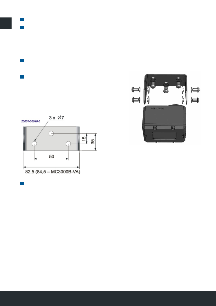
3.1 Montage ........................................................................................................... 7
3.2 Elektrischer Anschluss ..................................................................................... 8
3.3 Funktionsprüfung und Kamerajustage ............................................................. 9
3.4 Störungen ........................................................................................................ 9
4.1 Wartung/Reinigung ........................................................................................ 10
4.2 Lieferumfang .................................................................................................. 10
5 Umweltschutz................................................................................................. 10
Inhalt
Allgemeine Information zur Bedienungsanleitung
Vielen Dank für Ihr Vertrauen in AMETEK Motec Produkte. Wir entwickeln und
fertigen unsere Produkte mit größter Sorgfalt. Sollten Sie Fragen zum Produkt,
zur Inbetriebnahme oder Bedienung haben oder sollte das Produkt nicht Ihren
Erwartungen entsprechen, sprechen Sie uns jederzeit gerne an.
Bitte lesen Sie die Bedienungsanleitung vor der Benutzung des Produktes auf-
merksam durch. Sie ist zum späteren Gebrauch aufzubewahren. Unsere Pro-
dukte werden ständig weiterentwickelt. Die Motec GmbH behält sich das Recht
vor, das Produkt ohne Vorankündigung zu verändern.
1 Produktbeschreibung
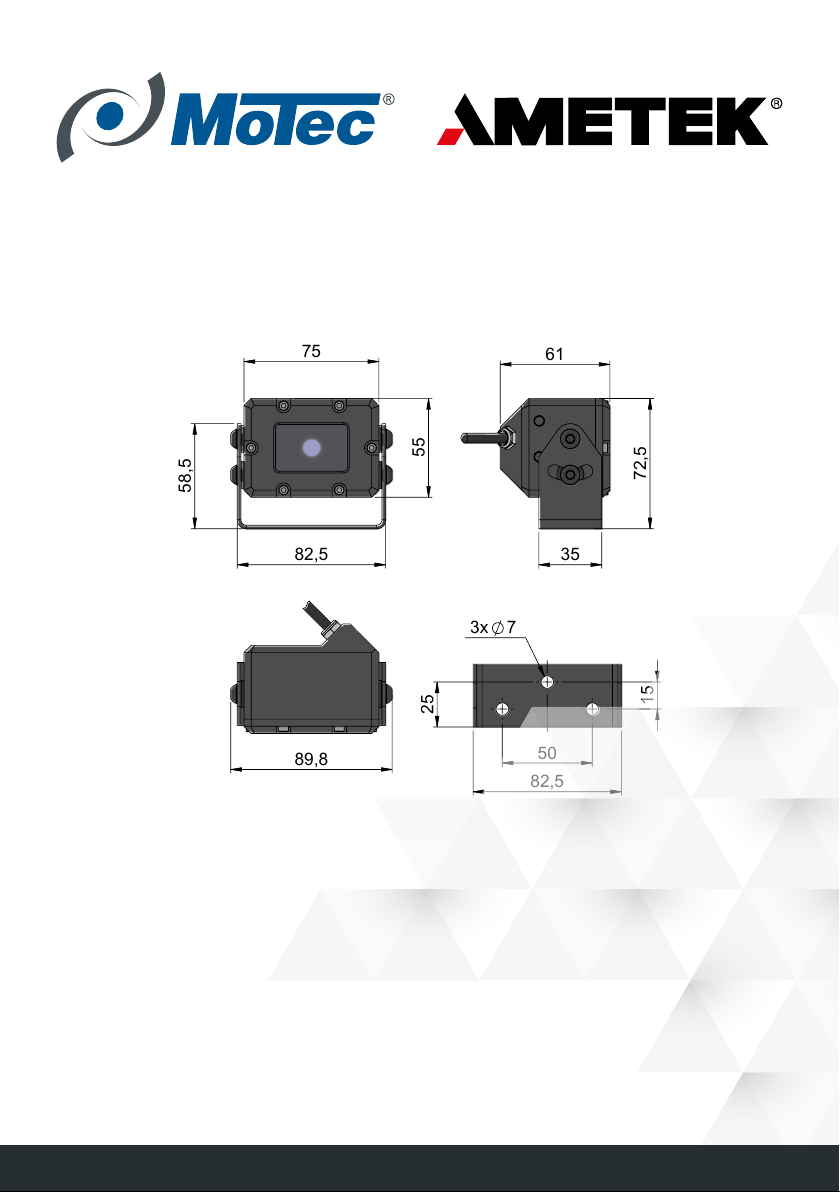
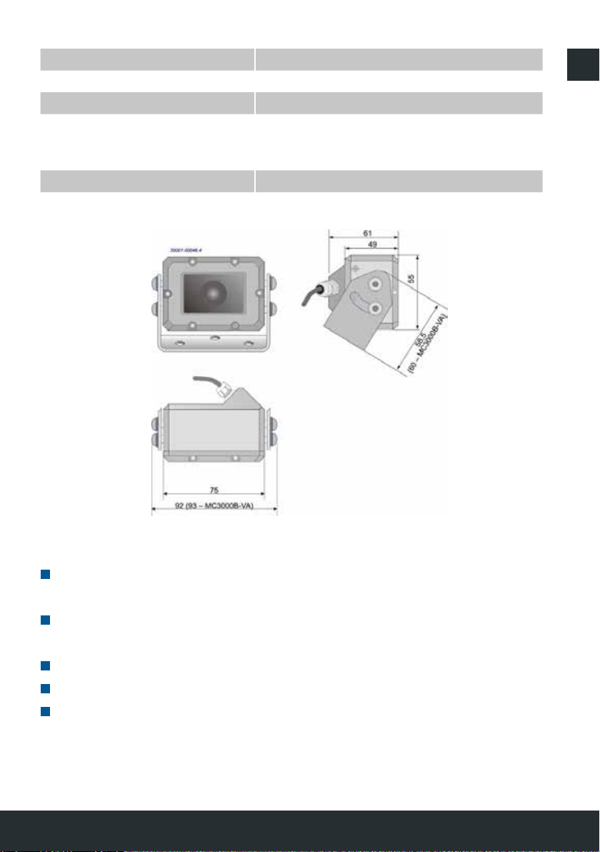
Die Kompaktkamera der Serie MC3000B/-VA ermöglicht dem Fahrer/Bediener
eines Fahrzeuges, Arbeitsbereiche ohne direkten Blickkontakt einzusehen. Bei
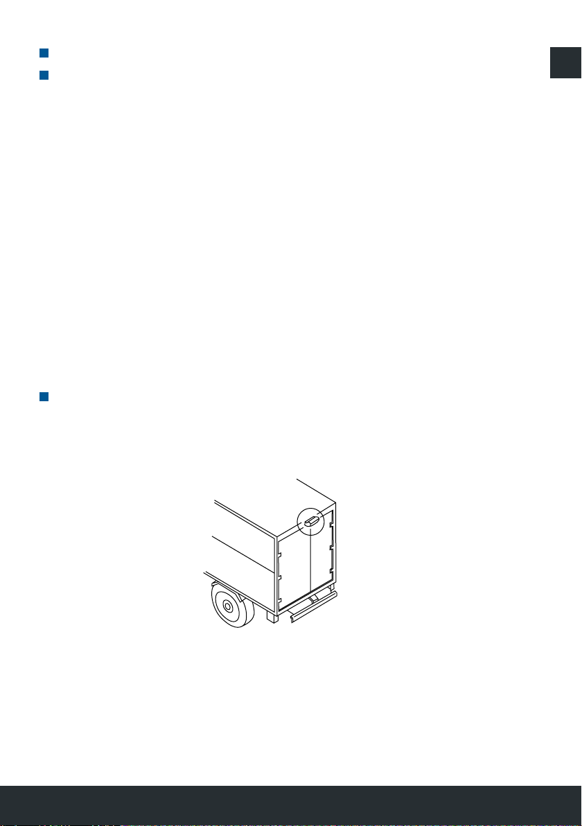
Gebrauch in Fahrzeugen kann die Kamera als Unterstützung beim Rückwärts-
fahren dienen.